

DRY CONTACTS MANUAL
TECHNICAL DOCUMENT
USER’S MANUAL FOR DRY CONTACT FUNCTIONS ON X-NOVA
Rev. Date Description
0 25/01/2016 First emission
1 22/02/2016 At paragraph 1 added indication “active low” for the input signal “IN” and corrected its
graphs to paragraph 2, 3 and 5.
2 28/07/2016 At point 7 Introduced the Photo of the final prototype
3 03/02/2017 At point 7 added Vinternal link on connector X7
4 03/04/2017 At point 7 added in the table cable color code 99.727 Mottura connected to the
connector X7
5 20/04/2017 Update of layout and graphics.
GENERAL INSTRUCTIONS
Mottura Serrature di Sicurezza S.p.A. thanks you for choosing this product and reminds you as follows:
- Read the instructions very carefully before installing the device or doing any maintenance work on the product.
- All assembly and connection procedures must be done according to the Rules of Good Practice as well as in
conformity to current law.
- DO NOT install the product in explosive environments or atmospheres or in the presence of flammable fumes/gases.
- DO NOT install the product on doors with risk of contact with water or atmospheric agents unless adequately
protected.
- Always switch off the power supply and disconnect all live parts before doing any installation or maintenance work
on the product. Take all possible precautions to eliminate the risk of electrical shock when doing the installation or
maintenance procedures described in this manual.
- In case of problems contact authorized dealers only.
When installing the lock, first connect all of the selected peripherals and then the power supply.
If you have to disconnect the wires, always disconnect the power supplies first.
The warranty does not cover damage due to negligence, carelessness or use in any manner not described in these
instructions.
Mottura Serrature di Sicurezza S.p.A. may change the characteristics of the products described in this document and
of the document itself at any time and without notice.
1/5
DRY CONTACTS MANUAL
TECHNICAL DOCUMENT
1) INPUT DESCRIPTION
The lock has three digital input (active low) to open it controllable by shorting the pins to GND with a dry contact.
If an open collector device is used, make sure the polarity is correct (i.e. collector/drain connected to IN –
emitter/source connected to GND)
IN1 = open the lock
IN2 = close the lock
IN3 = open followed by an automatic closure
The input signal must be a pulse.
1.a) HOW TO OPEN THE LOCK
Send a pulse (duration from 500 to 1500 ms) to the IN input you will get the full opening of the lock (latches and latch
bolt). The closing will take place automatically when you close the door.
2) OUTPUT DESCRIPTION
Five digital outputs of the type "open collector" provide the following information:
OUT1 : state latch bolt => (OPEN = outside ; CLOSE = inside)
OUT2 : state latches => (OPEN = not outside ; CLOSE = outside)
OUT3 : state door => (OPEN = open ; CLOSE = close )
OUT4 : error => (OPEN = all is OK ; CLOSE = error )
OUT5 : battery status => (OPEN = charged ; CLOSE = low)
Each output is TTL compatible (5V dc) and must comply with the following electrical requirements:
ABSOLUTE MAXIMUM RATINGS
Io sink max. <= 20 mAdc
Vo open max. <= 6 Vdc
Vo saturation max. <= 0,8 Vdc
These outputs are available only when the lock is awake, otherwise they are all "open" (N.O.) to reduce
consumption of energy.
To wake up the lock without opening it, piloting the input IN with a short pulse duration from 50 to 100 msec., the
status will be available immediately after the pulse, and the lock will remain awake for an additional 3 sec. (TIMEOUT
period).
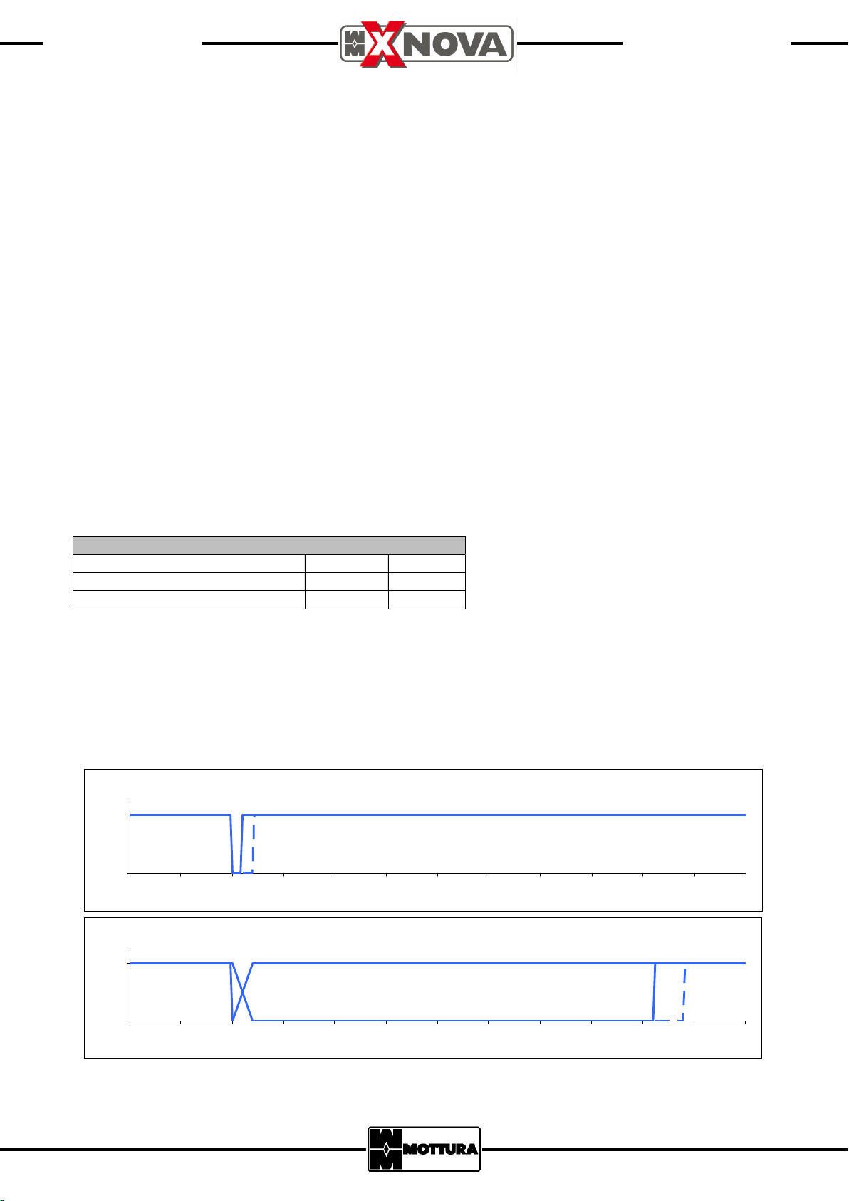
N.B.: The times indicated in charts are only for examples.
Input signal IN (continuous line = 50 ms ; dashed line = 100 ms)
1
Level
0
Level
1
0
0 250 500 750 1 000 125 0 1500 1750 200 0 225 0 2500 2750 30 00
mSec
All outputs represent their states in the timeout interval
0 250 500 750 1000 1250 15 00 1750 2000 22 50 2500 2750 300 0
mSec
2/5

DRY CONTACTS MANUAL
TECHNICAL DOCUMENT
Pulse to activate the lock on input signal IN
All outputs represe nt their states during the maneuver
3) HOW TO GET THE STATUS OF THE LOCK AND OPEN IT
Before performing a maneuver we suggest to know the state of the lock, then make an opening. The lock remains
awake (providing its status) for all the time necessary to complete the maneuvers.
In the following example we show this general sequence:
a) Wake up the lock with short time pulse at input IN (see the time 0.5 sec. in the charts).
b) read the status of the lock.
c) if necessary, open the lock with pulse at input IN (see the time 1 sec. in the charts)
d) wait for the lock to perform the work ( max 15 sec.).
e) finished the movement of the latches, lock still showing their status for 3 sec. (TIMEOUT period) then goes into
sleep.
1
Level
0
0 0,5 1 1,5 2 2 ,5 3 3,5 4 4,5 5 5 ,5 6 6,5 7 7,5 8 8,5 9 9,5 10
sec
Signal IN (continuous line = 500 ms ; dashed line = 1500 ms)
1
Level
0
0 0,5 1 1,5 2 2 ,5 3 3,5 4 4,5 5 5 ,5 6 6,5 7 7,5 8 8,5 9 9,5 10
Level
1
0
0 0,5 1 1,5 2 2 ,5 3 3,5 4 4,5 5 5,5 6 6,5 7 7,5 8 8,5 9 9,5 10
Time of execution of the maneuver
All these signals are in D.C. and referred to ground .
4) ERROR SIGNAL
When this signal is active there may be one of the following errors:
- stall of the latches
- Latch bolt not completely escaped
- Request the opening operation with the lock and door already open
- Accidental opening of the door during the closing operation,
- Detected the missing of mechanical cylinder (if equipped with a special sensor).
- latches or latch bolt in the wrong position
When the lock goes into sleep, error signal is reset.
sec
sec
3/5

DRY CONTACTS MANUAL
TECHNICAL DOCUMENT
5) INCREASE THE OPENING TIME OF THE LATCH BOLT
When you run a command OPEN (IN) the latch bolt comes out just after the opening of the door (dashed line).
If for some reason the door does not open, the latch bolt back outside after 10 sec anyway (Continuous line).
Open signal
Level
1
0
0 1 2 3 4 5 6 7 8 9 10 11 12
Spring latch status signal with door opened at sec. 2 or not (1 = inside ; 0 = outside)
Level
1
0
0 1 2 3 4 5 6 7 8 9 10 11 12
In case you want to keep the latch bolt inside for a longer time (max 2 minutes) while the door is still closed, you have
to keep active command OPEN (IN) for a long time: when the door is open, the latch bolt will be released immediately
outside.
If the door does not open the latch bolt will be outside 10 sec. after removing the OPEN (IN) command.
The following example keeps the lock open for a maximum time of 40 sec. If the door remains closed the OPEN (IN)
command (IN) will take up to 30 sec. after which the lock still holds the latch bolt for a further 10 sec. after that
releases it.
If the door is open during the 30 sec., command OPEN (IN) must be immediately removed.
In the graphs are indicated two cases: one in which the door is opened at the time 16 seconds (dotted lines) and the
other in which it does not open (continuous lines).
(NOTE : Check the port status through the signal OUT3 – state door)
Sec
Sec
Open signal
Level
1
0
0 2 4 6 8 10 12 14 16 18 20 22 24 26 28 30 32 34 36 38 40 42 44 46 48 5 0
Spring latch status signal with door opened at sec. 16 or not (1 = inside ; 0 = outside)
Level
1
0
0 2 4 6 8 10 12 14 16 18 20 22 24 26 28 30 32 34 36 38 40 42 44 46 48 50
Sec
Sec
6) POWER SUPPLY LOCK
Supply to the lock a mains voltage between 6.7 to 9.6 volts in direct current (Imax 2,5 A), or use 6 alkaline battery 1,5
V(Zn/MnO2) type "D" (LR20).
For mains voltage < 7.2 Vdc lock indicates that the battery is low.
For mains voltage < 6.6 Vdc the lock does not work.
4/5

TECHNICAL DOCUMENT
GND
internal (battery voltage or 9,5 Vmax from mains)
battery
rror
7) CONNECTIONS
DRY CONTACTS MANUAL
X8 X9 X7
X4 X5
Pin 1 Pin 1 Pin 1
Pin 1
CONNECTOR PIN COLOR * DESCRIPTION
X7 1 White
2 Brown INPUT2 – Close
3 Green V
4 Yellow INPUT1 – Open
5 Gray OUTPUT3 – Door state
6 Pink OUTPUT5 – Low
7 Blue OUTPUT4 – E
8 Red OUTPUT1 – Boltlatch state
9 Black OUTPUT2 – Latches state
10 Purple INPUT3 – Opening followed by automatic closing
X4 1 +12 Vdc (from the mains supply)
2 GND
X5 1 n.c.
2 +Vdc (from battery pack 9V )
3 GND
All other pins are not relevant [* Mottura cable color code 99.727]
Strada Antica di Francia, 34 - 10057 Sant'Ambrogio (TO) - Italia
Mottura Serrature di Sicurezza S.p.A.
Tel. +39 011 9343111 - Fax +39 011 9312427
www.mottura.it
5/5
 Loading...