

Mottura Xmode M 2.0 Installation Instructions Manual
POWERED ELECTRONIC LOCK
INSTALLATION INSTRUCTIONS
RECHARGEABLE
M 2.0

TABLE OF CONTENTS
1 - GENERAL INSTRUCTIONS ............................................................................. pag. 3
1.1 - WARRANTY TERMS
1.2 - LIMITS OF LIABILITY
2 - INSTALLATION .............................................................................................................. 4
2.1 - DRILLING DIAGRAM AND DIMENSIONS
2.2 - CYLINDER FIXING
3 - ESCUTCHEONS ........................................................................................................ 6
3.1 - INTERNAL BOARD VERSION
3.2 - EXTERNAL BOARD VERSION
4 - CONNECTING REMOTE CONTROL DEVICES ....................................................... 8
4.1 - EXTERNAL PERIPHERAL VOLTAGE-FREE CONTACT - INTERNAL BOARD VERSION
4.2 - EXTERNAL PERIPHERAL VOLTAGE-FREE CONTACT - EXTERNAL BOARD VERSION
4.3 - EXTERNAL PERIPHERAL MOTTURA REMOTE CONTROL - INTERNAL BOARD VERSION
4.4 - EXTERNAL PERIPHERAL MOTTURA REMOTE CONTROL - EXTERNAL BOARD VERSION
5 - CONNECTING THE POWER SUPPLY .................................................................... 10
6 - ELECTRICAL WIRING ................................................................................................. 17
6.1 - ELECTRIC WIRING - INTERNAL BOARD VERSION
6.2 - ELECTRIC WIRING - EXTERNAL BOARD VERSION
7 - AC/DC ADAPTER CONNECTION ............................................................................. 19
7.1 - MECHANICAL FIXING
7.2 - ELECTRICAL CONNECTION
7.3 - TECHNICAL DATA
2
99285GB- XMODE – INSTALLER MANUAL - REV. 01
1 - GENERAL INSTRUCTIONS
Mottura Serrature di Sicurezza S.p.A. thanks you for choosing this product and reminds you :
- To read all of these instructions very carefully before installing the lock or doing any maintenance work on the product.
- That all assembly and connection procedures must be done in conformity to the rules of Good Practice and to current law. DO NOT
install this product in rooms or atmospheres at risk of explosion or in the presence of ammable fumes/gases.
- Do not install the lock on doors with risk of contact with water or atmospheric agents if not properly protected.
- To switch o the power supply and disconnect all live parts before doing any installation or maintenance work on the product. Take
all possible precautions to eliminate the risk of electrical shock when doing the installation or maintenance procedures described in
this manual.
- The installer must deliver these instructions and all of the maintenance instructions to the user.
- Keep these instructions for future reference and attach the sales receipt to validate the warranty.
- In case of problems contact authorized dealers only.
This manual explains how to connect the lock according to a logical-functional sequence.
First connect all of the selected peripherals and then the power supply.
1. Connecting the escutcheons (allow lock to be controlled on door)
2. Connecting the remote control units (allow remote control of the lock)
3. Connecting the power supplies.
If you have to disconnect the wires, do the above steps in the reverse order, i.e., always disconnect the power supplies rst.
Mottura Serrature di Sicurezza S.p.A. may change the characteristics of the products described in these instructions at any time and without notice.
1.1 - WARRANTY TERMS
This product has been inspected by Mottura Serrature di Sicurezza S.p.A. and is guaranteed to be free of all manufacturing defects for the
time specied by current Italian law, starting on the date of purchase indicated on the sales receipt.
The warranty is in force if the sales receipt, showing details identifying the product, is exhibited to customer service personnel.
The warranty covers the replacement or repair of parts found defective at origin due to manufacturing defects. Costs of shipping to and
from service centers will be paid by the customer.
In case of repeated malfunctions of the same type or unrepairable defects, Mottura Serrature di Sicurezza S.p.A. may, at its own discretion,
replace the complete product. The warranty on the replaced product will continue until expiration of the original warranty.
If work is necessary at the customer’s home, the customer will be required to pay a charge for the costs of transfer of authorized technical
personnel.
Transport will be at the customer’s risk if the product is sent by the customer and at the authorized technician’s risk if the product is picked
up and transported by the technician.
1.2 - LIMITS OF LIABILITY
The warranty does not cover damage due to:
- negligence, carelessness or use in any manner not described in these instructions
- lack of protection of the lock prior to carrying out any work operations on the door, such as drilling or welding (welds, panel holes, structure holes, etc.), which may generate waste materials that will hinder the correct operation of the lock upon entering its mechanism
- maintenance performed in any manner not described in these instructions or by unauthorized personnel
- use of non-original accessories/components Mottura
- transport without the necessary precautions
and from any circumstances that cannot be attributed to manufacturing defects.
Work temperature: -10°C to +55°C. The batteries guarantee correct operation of the lock in the specied temperature range. If such temperature extremes are approached or exceeded, battery performance may decrease rapidly, with possible malfunction of the electrical part.
In case of extremely low temperatures, it is advisable to power the lock from the mains by using the 230/12 V transformer.
In addition, Mottura Serrature di Sicurezza S.p.A. declines all liability for any damage to persons or property deriving from failure to observe all of the precautions described herein.
N.B. Mechanical lock operation is guaranteed even when the electronics of the lock has no anomaly. This excludes any
electronic safety level. Mechanical keys should therefore only be used by the owner and/or by extremely trustworthy
persons.
3
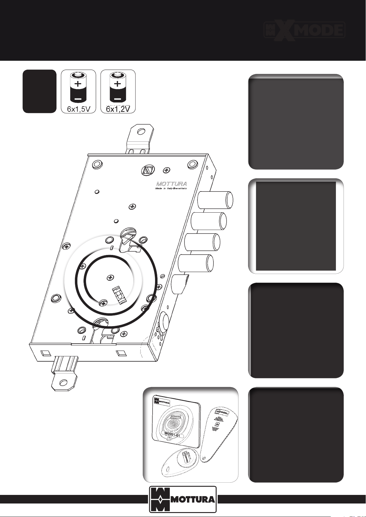
2 - INSTALLATION
Fix the lock to the door structure by using all of the fasteners: side attachments (A), bushings (B) or mortise-type (C) (Fig. 1). In order to work correctly,
the lock should be xed in a vertical position. The lock may not work properly if installed or used in a dierent position. For correct operation of the
lock, the spring latch must be able to protrude freely without frictioning when the door is open or closed.
If necessary, drill spaces in the door structure to hold the battery pack and the box for the electronic board (supplied in the pack for the selected version) in a non-binding position dened only by the length of the wires and by internal dimensions due to door conguration (opening limiter, switchlocks, etc.). Drill the frame for the door status sensor. For these drillings, see the attached mounting diagram in Fig. 2. If you are mounting switchlocks,
always provide sucient clearance between the bar and the upper and lower tabs both when the lock is open and when it is closed, so as to prevent
strain that could damage the motor. Fasten the battery pack, if required, and wire it as shown in paragraphs 3, 4, 5, 6 (diagrams Fig.3RH and Fig.3LH
– pages 18/19), (depending on door version), preparing the connections for the board holder, lock and the internal and external escutcheons using
the wires supplied as standard.
Protect the lock before doing any work on the door that could produce waste material (soldering, drilling of panels, drilling of structure,
etc.) that might enter the lock and impair its functioning. Do not insert the batteries into the battery holder until nished xing to avoid
short circuits that may damage the system.
WARNING! When the door is completely mounted and perfectly positioned, run the rst checks on the lock (opening/closing) in mechanical mode to make sure there is no frictioning on the levers (bars/switchlocks) or on the key when turning.
These problems could impair correct electronic operation of the lock and cause permanent malfunction. Mottura Serrature di Sicurezza
S.p.A. declines all liability if this procedure is not performed and, in such case, all warranties on the product will lapse.
If a mains powered connection is provided, it is advisable to use grommet 99144 (not included) between xed upright and leaf, attaching it as
shown in the detail (Fig. 3RH and Fig. 3LH) and instructions attached to the grommet pack.
A = SIDE ATTACHEMENTS
B = BUSHINGS
C = MORTISE-TYPE
A
B
B
A
C
B
B
Variation in
bolt centre
distances
SENSOR
A
A
Fig.1
4
99285GB- XMODE – INSTALLER MANUAL - REV. 01
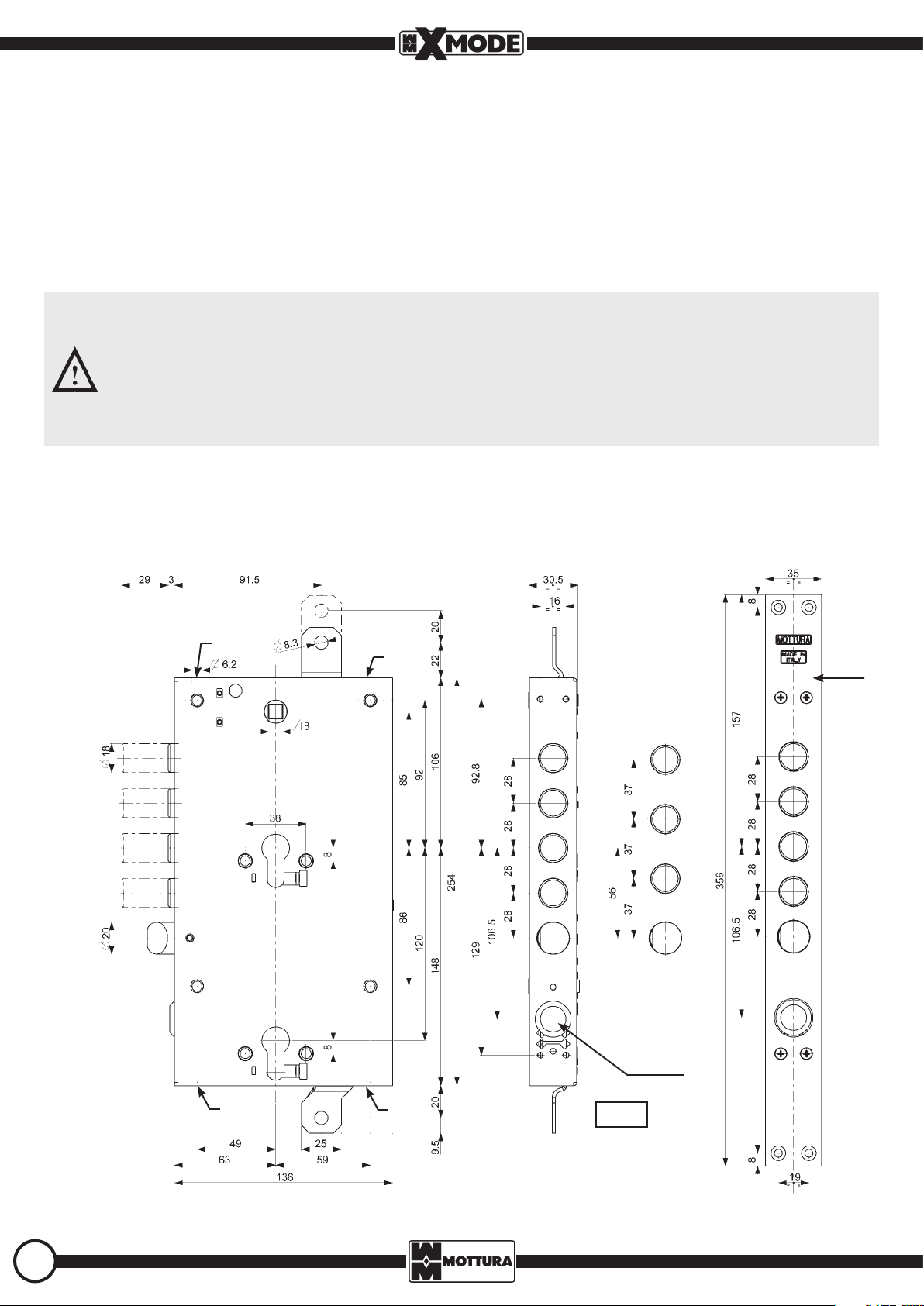
2.1 - DRILLING DIAGRAM
(CHANGEABLE POSITIONS)
AND DIMENSIONS
DOOR
STATUS
SENSOR
Variation in
bolt centre
distances
BOARD HOLDER
EXTERNAL ELECTRONIC
BOARD VERSION
DOOR
STATUS
SENSOR
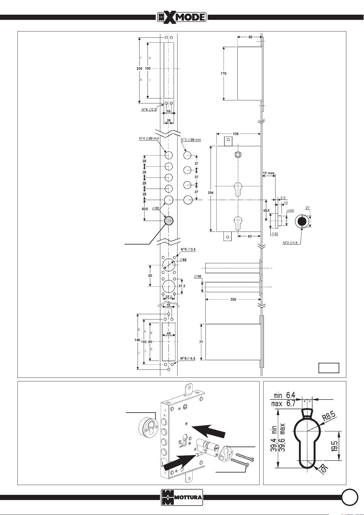
2.2 - CYLINDER FIXING
For proper functioning of the lock, we
recommend installation of a MOTTURA
CHAMPIONS® double or half Europrole
cylinder (according to application) (DO NOT
use cylinders with knobs). For better protection of the cylinder from the outer side of
the door, we recommend the use of MOTTURA DEFENDER® systems. For these articles (not included in the pack), please see
MOTTURA catalogs. Alternatively use European cylinder with the dimension shown in
the diagram.
BATTERY HOLDER
DOUBLE TUBE
VERSION
BATTERY HOLDER
CASSETTE
VERSION
Fig.2
Defender®
2
99.066
1
99.293/L
5
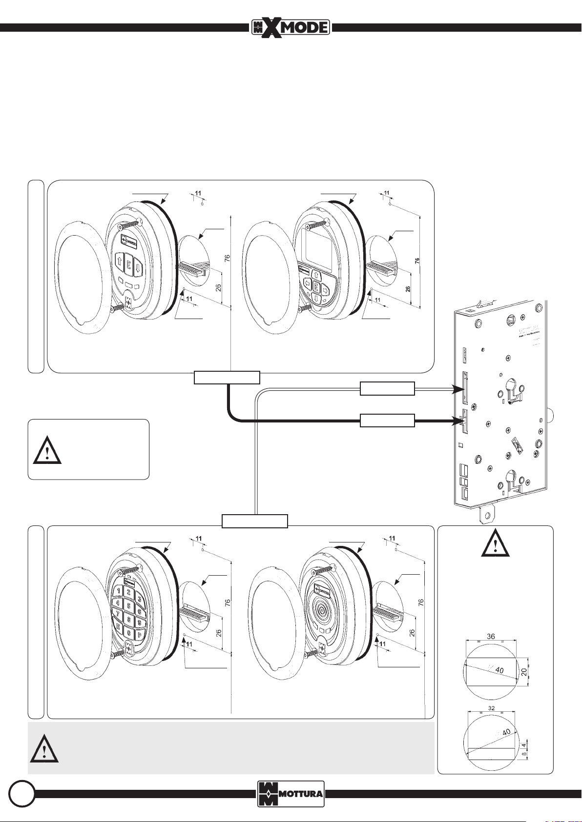
3 - ESCUTCHEONS
3.1 - INTERNAL BOARD VERSION
The escutcheon is designed for installation on the door panel in a position near the two other user work zones (handle and cylinder escutcheon).
When installing, use the drilling diagram shown below and remember that the connection cable is 1000 mm long. For installation other than
as indicated, check that the cable length allows for such installation without hinder movement of the bars or limiter; otherwise, contact your
authorized dealer. Before xing the escutcheon to the panel (with the 2 screws equipped), position the sealing strip in its seat in the rear of the
escutcheon (see detail – rear view), then insert the connector securely into place. When xing is complete, insert the metallic escutcheon cover,
which is available in dierent nishes. The escutcheons have an IP51 protection rating.
O-RING
KEYBOARD VERSION
ART. 99.685
Protect the
cables against
tampering.
O-RING
Ø40
N°2 Ø2 N°2 Ø2
DISPLAY VERSION
ART. 99.688
Cable 99.698
Cable 99.699
Cable 99.698
Ø40
6
Cable 99.699
O-RING O-RING
Ø40*
OUTSIDE DOOR INSIDE DOOR
KEYBOARD + TRANSPONDER
VERSION ART. 99.686
The internal and external escutcheons are interchangeable. You can replace keyboard version (Art.99685)
with display version (Art. 99688) and the transponder-only escutcheon (Art. 99687) with the keyboard/transponder escutcheon (Art. 99686) at any time. Always switch o the power supply before making any replacement. Remember that all of the codes and transponder keys are memorized in the lock card.
N°2 Ø2
TRANSPONDER VERSION
ART. 99.687
99285GB- XMODE – INSTALLER MANUAL - REV. 01
Ø40*
N°2 Ø2
* 40 mm diameter hole to be
drilled only on the external panel. Cut a 36x20 mm opening
on the plate if the external
panel has thickness less than/
equal to 6 mm; otherwise, cut a
32x8 mm slot.
 Loading...