

Mottura GOOUT 86G271, GOOUT 86G270, GOOUT 86G371, GOOUT 86G370 Maintance Manual
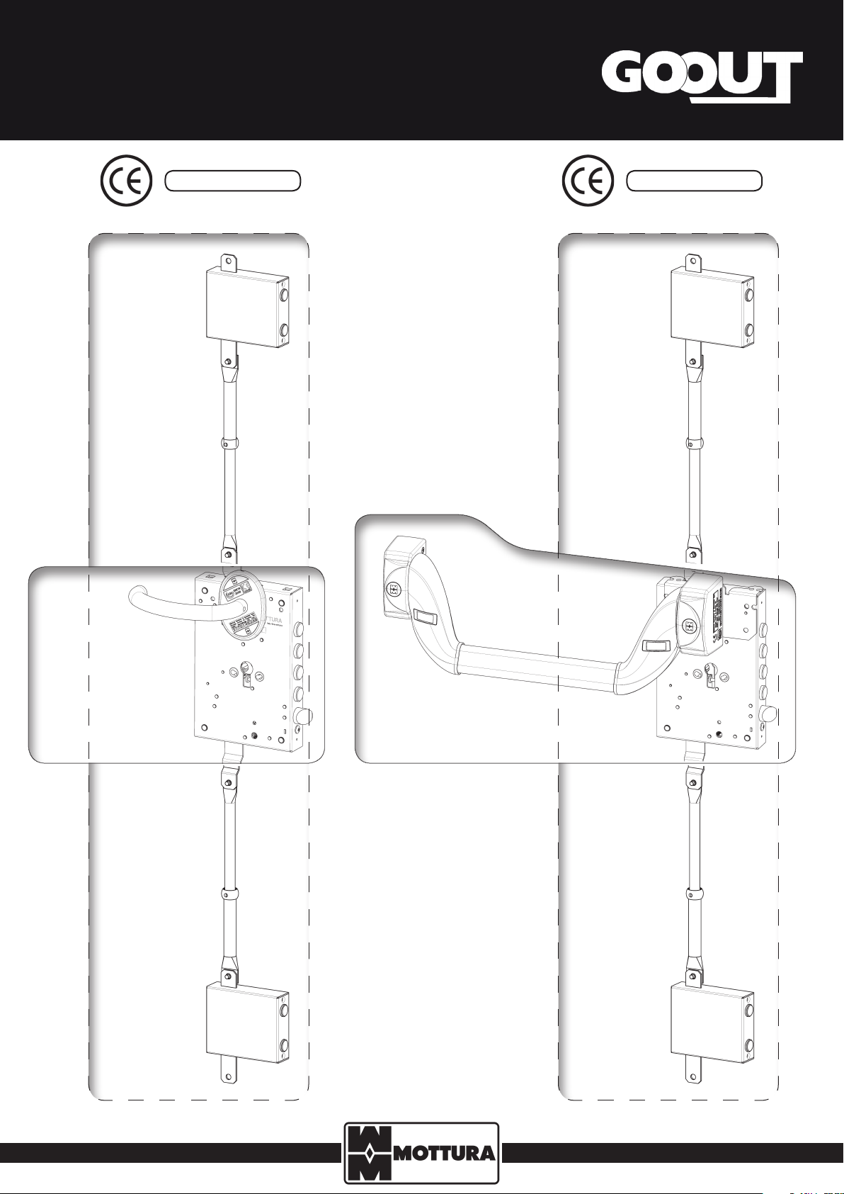
SECURITY LOCK with PANIC EXIT DEVICE
INSTALLATION, USE AND
MAINTENANCE INSTRUCTIONS
EN 179 : 2008 EN 1125 : 2008
86G271
THREE-POINT
VERSION
86G270
SIDE
VERSION
86G371
THREE-POINT
VERSION
86G370
SIDE
VERSION
IMPORTANT WARNING
The security characteristics of this product are essential for guaranteeing the safety of individuals and for conformity to EN 179 and EN
1125. DO NOT modify this product in any way, except as described in these instructions.
The anti-panic device has been certied for use on single leaf doors no larger than 2520 x 1320 mm (H x W) with weight over 200 kg.
As required by the standard, it is recommended that the owner of the business and/or their authorized representative perform the following routine maintenance checks at intervals of no more than one month:
- inspect and activate the anti-panic device to verify that all components are in a satisfactory working condition;
- verify that the holes on the striker plate are not obstructed;
- verify that no locks or other locking devices have been added on the door in addition to the initial device;
- verify the rules governing the installation and maintenance established by the Ministerial Decree of 11/03/2004;
- with a dynamometer, periodically check the working force needed to open the exit device. Make sure the working force has not changed
signicantly from the force measured at the time of installation.
The lock operating device should be lubricated, using Mottura lubricant (for locks), once a year or whenever a stiening of the mechanisms
is detected. Do not use oil or other lubricants: the use of such substances promotes the deposit of dust and fragments that may aect the
correct operation of the lock.
Warning
Mottura Serrature di Sicurezza S.p.A., thanks you for your condence in choosing this product and recommends:
· to read the instructions carefully before proceeding with the installation;
· to hand over all the instructions to the user by the installer;
· to keep the instructions for future reference and attach the receipt to validate the warranty;
· to contact the dealer only if a problem occurs.
The characteristics of the products described in these instructions may be subject to change by Mottura Serrature di Sicurezza S.p.A. at any time
without prior notice.
WARRANTY conditions
This product tested by Mottura Serrature di Sicurezza S.p.A. is guaranteed against all manufacturing defects for the duration of the period stipulated by applicable Italian legislation from the date of purchase demonstrated in a scal receipt.
Guarantee claims may only be accepted upon presentation of the scal sales receipt, containing the details identifying the product, to technical
support personnel. The guarantee covers the replacement or repair of parts found to have manufacturing defects. The guarantee does not cover
transport costs to and from the technical support centre, which remain at the sole expense of the customer. In the event of a recurring fault of
the same cause, or of an unrepairable fault, Mottura Serrature di Sicurezza S.p.A., at its sole discretion, may decide to replace the entire product.
The guarantee will continue to cover the replacement product until the expiry of the original contract.
If a home call-out should be necessary, the customer is required to pay - if asked to- a call-out fee for the travel expenses of the authorized
service personnel. The customer is solely responsible for any transport damage in the event of direct shipment, or the sole responsibility of the
authorised technician where the product is collected and transported by the technician.
Limited responsibility
Not covered under warranty are damages resulting from the improper installation not in accordance with the instructions attached to the product, negligence, carelessness or inappropriate operation, maintenance by unauthorized personnel, transport without due care and attention
and in any case by circumstances that cannot result from manufacturing defects.
Mottura serrature di sicurezza S.p.A. declines any liability for possible damages caused to persons or property resulting from the failure to observe the indicated precautions for use.
GOOUT locks are certied by the ICIM Institute, based on reference standards, with regard to each complete component (specically: lock, switchlocks, bars). Any modication of the product assembly or installation not conforming to this instruction manual
will automatically void such certication. In these cases, the party that makes such modication/replacements will be responsible
for conformity to the reference standards.
General information
To ensure good operation of the lock and panic exit device, check that the door is in good condition (planarity, solidity, rigidity). The door and
frame must be built of suciently rigid material, such as welded steel or aluminum proles, to ensure that any distortion during use does not
exceed 5 mm at any position of the lock attachment points. Also check that the device and the door open and close without any obstruction.
If the panic exit device is to be installed on a glass door, the glass MUST be tempered and laminated. Panic exit devices are not intended to be
used on doors that open in both directions (entrance and exit) unless specically designed by the manufacturer.
If you have to use a door closer or a closing switch to return the door to closed position, be careful not to make the door dicult to use by
children, the elderly, and invalids.
Before assembling a panic exit device on a smoke/re door, check the re resistance certication for the door on which the exit device was tted
during tests to ensure it is suitable for use on the re door. It is extremely important NOT to use an exit device on a re door whose re resistance
time exceeds the time for which the device was approved.
A sign stating “Push bar to open” or a pictogram (photo to the right) must be placed on the inside of the door immediately above the horizontal bar or on the bar itself if the bar has a at surface area sucient for the required letter
size. The pictogram must have an area not smaller than 8,000 mm2, with white letters on a green background. The
pictogram must be positioned so that the arrow points to the exit device, when installed (EN 7546 – Italian Decree
Law 493 of 14/08/1996).
2
99289GB - GOOUT - REV. 00
Istruzioni di montaggio
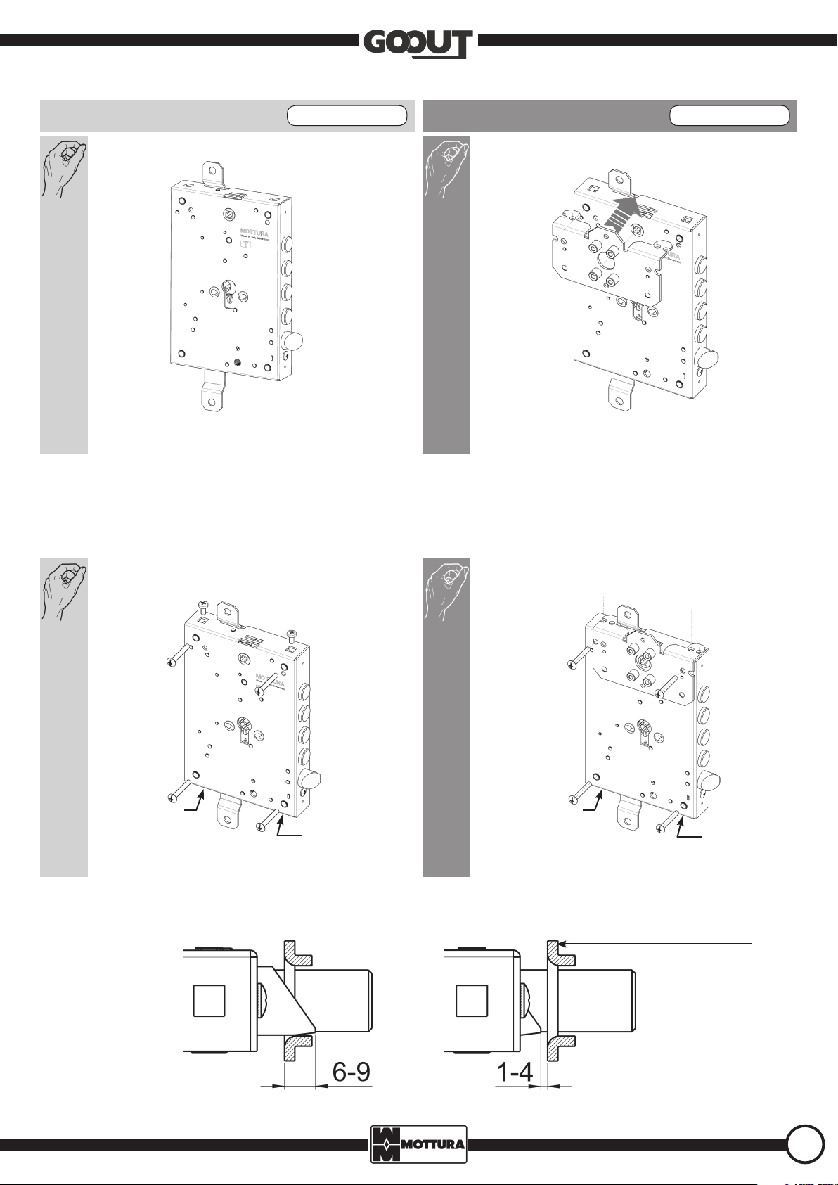
EMERGENCY HANDLE UNI EN 179 PANIC-BAR VERSION UNI EN 1125
Center the plate (supplied) on the lock by using the two pins on
the lock.
Fix the lock to the frame (door xing surface) with M6 screws (not supplied), using the bushings (ref. B) on the lock. For side connection, use M6 cage nuts
(ref. A). When calculating lock xing position, remember that the anti-panic device/emergency handle is located from 900 to 1100 mm above nished
oor level with the door closed (if you know that most of the people using the rooms are children, consider lowering the bar/handle).
N.B. Use all of the xing points A (side connections) or B (bushings) when mounting the lock.
A
A
B
B
A
For the lock to work correctly, after mounting there must be maximum clearance of 4 mm between the deadbolt (in retracted position) and the door
jamb (or striker plate).
A
B
B
A
B
B
B
A
A
STRIKER PLATE NOT SUPPLIED
B
A
3
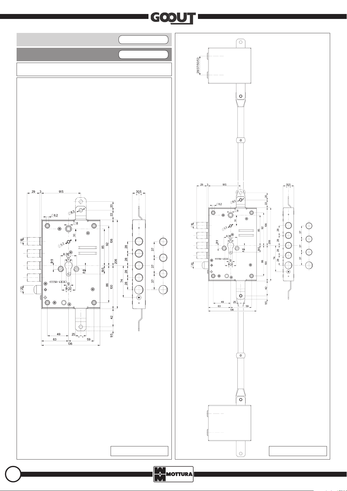
EMERGENCY HANDLE UNI EN 179
PANIC-BAR VERSION UNI EN 1125
A = SIDE CONNECTIONS - B = BUSHINGS - M = HANDLE
A
A
B
M
B
A
A
B
B
A
B
M
B
A
A
B
B
A
SIDE VERSION 3-POINT VERSION
4
99289GB - GOOUT - REV. 00
 Loading...