

Motrona ZU 252 Operating Instructions Manual
control – motion – interface
ZU 252
Incremental Counter Module
With Analogue Output and Serial Interface
motrona GmbH
Zwischen den Wegen 32
78239 Rielasingen - Germany
Tel. +49 (0)7731-9332-0
Fax +49 (0)7731-9332-30
info@motrona.com
www.motrona.com
Counter suitable for quadrature signals (A/B, 90º) as well as single channel inputs
Counting inputs selectable to TTL/ RS422 format or to HTL / 10-30 volts format
Maximum counting frequency 1 MHz
Analogue outputs +/-10 V, 0-20 mA and 4-20 mA, polarity following the sign of the
internal counter
Analogue conversion time 1 msec only
RS 232 and RS 485 interfaces for serial readout of the counter
Also suitable for conversion of the sum or the difference of two separate counts
Facility for free linearization of the analogue output by 16 interpolation points
Easy to set up by TEACH procedure, or by PC and Windows software
Operating Instructions
ZU25201e_e.doc / Sep-13 Page 1 / 36

Safety Instructions
Version:
Description
:ZU25201a
/ HK/AF/
Apr.08
Original version
ZU
25201b
/ HK/AF/
Dez.08
Explanation DIL2/7+8 and other supplements
ZU25201c/pp/Jan.12
Name changed f
rom “Register Code” to “Serial Value”
ZU25201d/pp/Apr.12
Implementation of Chapter 18 “Command List”
ZU25201e/af/nw/
Sep.13
Small Corrections
This manual is an essential part of the unit and contains important hints about
function, correct handling and commissioning. Non-observance can result in
damage to the unit or the machine or even in injury to persons using the
equipment!
The unit must only be installed, connected and activated by a qualified electrician
It is a must to observe all general and also all country-specific and application-
specific safety standards
When this unit is used with applications where failure or maloperation could cause
damage to a machine or hazard to the operating staff, it is indispensable to meet
effective precautions in order to avoid such consequences
Regarding installation, wiring, environmental conditions, screening of cables and
earthing, you must follow the general standards of industrial automation industry
- Errors and omissions excepted –
ZU25201e_e.doc / Sep-13 Page 2 / 36

ZU25201e_e.doc / Sep-13 Page 3 / 36

Table of Contents
1. Compatibility Hint ........................................................................................................ 5
2. Introduction.................................................................................................................. 6
3. Applicable Encoders and Sensors ................................................................................ 7
4. Terminal Assignment ................................................................................................... 8
4.1. Incremental encoders TTL / RS 422 ......................................................................8
4.2. Incremental encoder HTL / 12-30V........................................................................9
4.3. Proximity switches, photocells etc........................................................................9
4.4. HTL Input “Control”...............................................................................................9
4.5. Analogue outputs..................................................................................................9
4.6. Serial interfaces..................................................................................................10
5. DIL Switch Settings.................................................................................................... 11
5.1. Basic mode of operation and power-down memory setting...............................11
5.2. Impulse levels and symmetric / asymmetric input formats................................12
5.3. Analogue output format......................................................................................13
5.4. Selecting the RS232 or the RS485 serial interface.............................................14
5.5. Teach function, Test function, loading of default settings.................................14
6. Setup Procedure......................................................................................................... 15
6.1. Operation as single channel counter (without direction signal) or as positional
counter (with direction signal).........................................................................................16
6.2. Operation as a summing or differential counter with two independent impulse
inputs (A+B, A-B)..............................................................................................................16
7. Readout of the Actual Counter State by Serial Communication................................ 17
8. PC Setup Using the OS3.2 Operator Software............................................................ 18
9. Displays and Softkeys ................................................................................................ 19
10. Parameter Settings .................................................................................................... 20
11. Free Programmable Linearization ............................................................................... 26
12. Monitor Functions...................................................................................................... 28
13. Data Readout via Serial Interface .............................................................................. 30
14. Test Functions............................................................................................................ 31
15. Dimensions ................................................................................................................ 32
16. Technical Specifications ............................................................................................ 33
17. Parameter List............................................................................................................ 34
18. Command List ............................................................................................................ 35
19. Setup Form................................................................................................................. 36
ZU25201e_e.doc / Sep-13 Page 4 / 36

1. Compatibility Hint
This product is a successor model of the thousandfold approved converter type ZU251. The new
product is suitable for a 100% replacement of the previous model, however some differences
must be observed with DIL switch settings and parameter settings.
Some essential advantages of ZU252 compared to ZU251 are:
Maximum frequency 1 MHz (instead of 500 kHz)
Capability to accept even single-ended TTL input signals
(i.e. TTL inputs A and B only, without inverted signals /A and /B)
Setting of analogue formats +/-10V, +10V, 0-20 mA and 4-20 mA can be done by
supplementary DIL switch (no more PC required)
Enhanced auxiliary output 5 V / 250 mA for encoder supply
ZU25201e_e.doc / Sep-13 Page 5 / 36

2. Introduction
A
B
a.b.c.
ZU 252 represents a small and low-cost, but highly performing converter for industrial
applications, where incremental counting of positions or events must be converted to either
analogue format or serial data. The unit has been designed as a compact module with 12 screw
terminals and a 9-position SUB-D connector (female). The housing is suitable for standard DIN
rail mounting.
The impulse input side provides channels A, B and also the inverted lines /A, /B which should
be used with TTL/ RS422 input signals. The unit can count and convert the following formats to
analogue and serial:
a. Up/down count with quadrature input (A/B, 90).
The polarity of the analogue output and the sign of the serial data depend on the sign of
the actual counting result
b. Single channel impulses on channel A.
Input B sets the counting direction and therefore also the polarity of the output
(LOW = negative, HIGH = positive).
Please observe:
Open NPN inputs are HIGH
Open PNP inputs are LOW
Open RS422 inputs may cause problems, therefore please set unused inputs to HTL
by means of the DIL switches
c. Dual count of fully independent events on channels A and B, where the output signal
represents the sum or the difference of both counts.
A
B
A and B, quadrature 90°
A
B
A=impulse, B=static direction signal
-
+
A and B: independant counting events
The definitions for “zero analogue output” and “full scale analogue output” definition can be
set over the full counting range of +/-8 decades (-99 999 999 to +99 999 999)
ZU25201e_e.doc / Sep-13 Page 6 / 36

3. Applicable Encoders and Sensors
The converter can accept the following impulse sources:
The ZU252 converter can accept the following impulse sources:
Quadrature encoders with HTL level output (10 – 30 V) and either PNP or NPN or Push-
Pull or NAMUR characteristics, using A and B outputs wit 90° displacement
Single channel impulse sources like proximity switches or photocells, providing HTL
level at PNP or NPN or Namur characteristics
TTL / RS422 quadrature encoders with output lines A, /A ,B and /B
Symmetric single channel sources with TTL / RS422 output, providing differential
signals (i.e. A and /A)
Asymmetric single channel sources with TTL level (without inverted signals, i.e. A only)
In general, HTL encoders will be supplied from the same source as the converter itself.
For supply of TTL encoders, the unit provides an auxiliary output of 5.5 volts
(stabilized, max. 250 mA).
ZU25201e_e.doc / Sep-13 Page 7 / 36
4. Terminal Assignment
1
2
3
4
5
6
7
8
9
1
0
1
1
1
2
Analogue out +/-10V
TTL: Input /B HTL: n.c.
TTL: Input B HTL: Input B
Analogue GND ( - )
+18...30 VDC (typ. 70 mA)
P
O
W
E
R
892
3
+
-
TTL encoder
ZU 252 converter
AABBAAB
Ba)892311 (+5.5V)
+
-
TTL encoder
ZU 252 converter
Screen
AABBAAB
B
+ext
-ext
We recommend connecting the Minus wire of the power supply to earth potential.
Please observe that, under poor earthing and grounding conditions, multiple earth connections
of screens and GND terminals may cause severe problems. In such cases it may be better to
have only one central earthing point for the whole system.
GND terminals 4, 6 and 12 are connected internally. Depending on input voltage and load of the
auxiliary voltage output, the total power consumption of the unit is approx. 70 mA
(see specifications).
0-20mA / 4-20mA out
TTL: Input /A HTL: n.c.
TTL: Input A HTL: Input A
Control
Aux. 5.5V out (max. 250 mA)
GND ( - )
GND ( - )
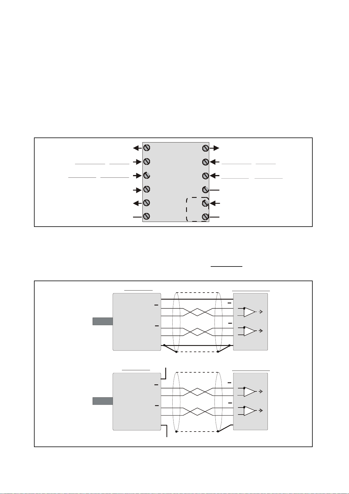
4.1. Incremental encoders TTL / RS 422
If applicable, the encoder can be supplied from the ZU252 converter. Where the encoder is
already supplied from a remote source, we recommend fully differential operation, with no
GND connection between encoder and converter (see figures a. and b.)
Screen
11 (+5.5V)
12 (GND)
ZU25201e_e.doc / Sep-13 Page 8 / 36
b)
12 (GND)

4.2. Incremental encoder HTL / 12-30V
9
3
GND
ZU 252 converter
+24V
+/- 10V
(R = 0 - 270 Ohms)
Screen
The encoder may be supplied from the same source as the converter, or from another source.
HTL encoder
+
A
B
Screen
12 (GND)
4.3. Proximity switches, photocells etc.
This connection is fully similar to a HTL incremental encoder. With single-channel operation,
input B remains unconnected or can be used to select the output polarity. With use of two
independent counting events for forming the sum or the difference, input B operates as the
second counting input.
For use of sensors providing 2-wire NAMUR characteristics:
Set the inputs to HTL and NPN
Connect the positive wire of the sensor to the corresponding input and the negative
wire to GND.
4.4. HTL Input “Control”
The HTL control input available on terminal 10 provides programmable characteristics and
functions for activation of different commands (e.g. Reset, see parameter “Input setting)
4.5. Analogue outputs
The unit provides a +/-10V voltage output and a 0-20 mA / 4-20 mA current output at a
resolution of 14 bits, i.e. the voltage output operates in steps of 1.25 mV and the current output
operates in steps of 2.5 µA. The nominal load of the voltage output is 2 mA, the current output
accepts loads between 0 Ohms and 270 Ohms.
The analogue ground uses a separate terminal, which however internally is connected to the
GND potential of the power supply.
Vout
GND
1
(Imax = 2 mA)
4
ZU25201e_e.doc / Sep-13 Page 9 / 36
Iout
7
20 mA
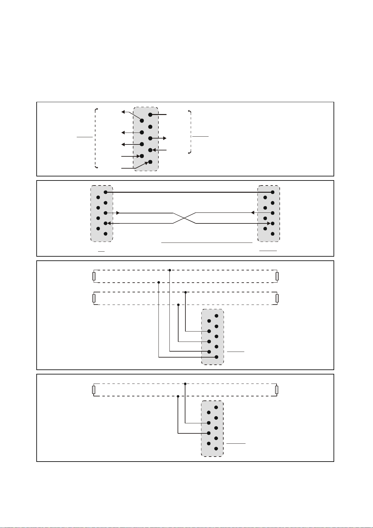
4.6. Serial interfaces
5
4
3
2
1
9
8
7
6
Sub-D-9 (female on unit site)
5
4
3
2
1
9
8
7
6
5
4
3
2
1
9
8
7
6
GND
TxD
RxDPCZU 252
Please connect only pins 2, 3 and 5 !
5
4
3
2
1
9
8
7
6
5
4
3
2
1
9
8
7
6
T+
120 Ohms
5
4
3
2
1
9
8
7
6
5
4
3
2
1
9
8
7
6
T+
The unit provides a RS232 interface and a RS485 interface, however only one of the two can be
used at a time. Serial communication allows to read out the counting result and to set
parameters and variables by PC, according to need.
RS485
+5V
T+
T-
GND int.
TxD
RxD
RS232
R+
R-
5
5
9
9
4
4
8 7
8 7
3
3
2
2
6
6
1
1
RS232:
120 Ohms 120 Ohms
120 Ohms
TR+
R-
ZU25201e_e.doc / Sep-13 Page 10 / 36
RS485- Bus
( 4- wire )
120 Ohms
RS485- Bus
( 2- wire )
T+
T-
R+
R-
T-
ZU 252
120 Ohms
ZU 252
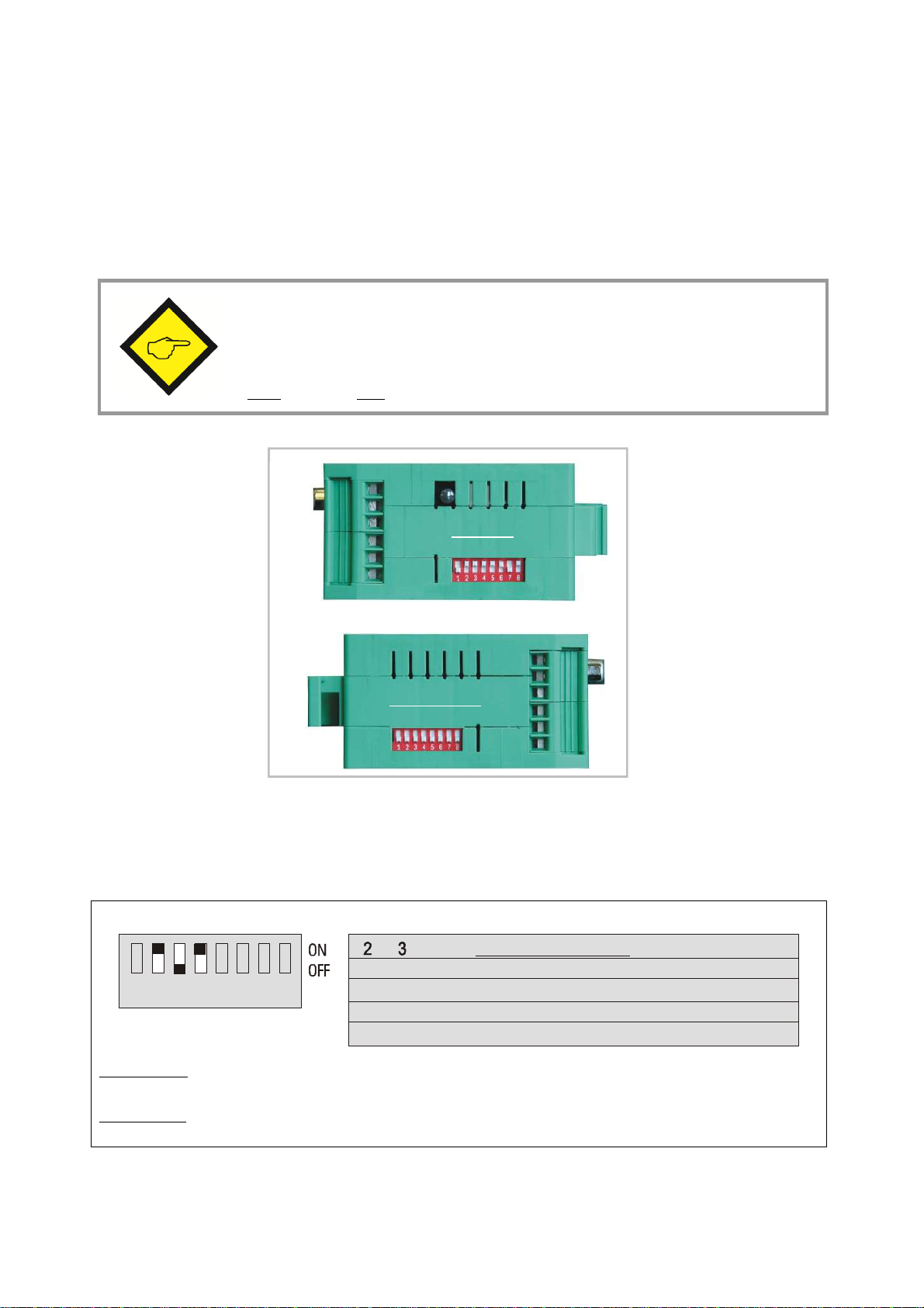
5. DIL Switch Settings
Mode of operation
Quadrature operation A / B / 90°
A = counting input, B = direction control (up/dn)
DIL1
There is one 8-position switch located on the top side (DIL1), and another 8-position switch is
located on the bottom side of the unit (DIL2). These switches provide major settings of the
desired properties of the unit.
Changes of switch settings will become active only after cycling the power
supply of the unit!
Positions 7 and 8 of switch DIL2 are for internal factory use only and must
both be set to OFF at any time during normal operation
Teach button
Top side
Switch DIL1
Bottom side
Switch DIL2
5.1. Basic mode of operation and power-down memory setting
Positions 2 and 3 of switch DIL1 on the top side set the mode of operation, and position 4
allows setting of the power-down behavior of the unit:
on on
1 2 3 4 5 6 7 8
Position 4 off: Power-down memory off. Upon power up the counter either resets to zero or sets to the
value programmed under parameter „Set Value“ *)
Position 4 on: Power-down memory on. Upon power up the counter re-loads the previous value before
power down
on off
off on
off off
Input A only
Sum A + B or difference A - B
*) see Parameter „Power-up Mode“
ZU25201e_e.doc / Sep-13 Page 11 / 36
 Loading...