

Motrona ZU 251, ZU25101B, ZU25102A Operating Instructions Manual
control – motion – interface
ZU 251
Incremental Counter Module
With Analogue Output and Serial Interface
ELEKTRO-TRADING sp. z o.o
Tel. +48 (0-32) 734-55-72
Tel/Fax +48 (0-32) 734-55-70
E-Mail et@elektro-trading.com.pl
http://www.elektro-trading.com.pl
• Counter suitable for quadrature signals (A/B, 90º) as well as single channel inputs
• Counting inputs selectable to TTL/ RS422 format or to HTL / 10-30 volts format
• Maximum counting frequency 500 kHz
• Analogue outputs +/-10 V, 0-20 mA and 4-20 mA, polarity following the sign of the
internal counter
• Analogue conversion time 1 msec only
• RS 232 and RS 485 interfaces for serial readout of the counter
• Also suitable for conversion of the sum or the difference of two separate counts
• Facility for free linearization of the analogue output by 16 interpolation points
• Easy to set up by TEACH procedure, or by PC and Windows software
Operating Instructions
ZU25102A_e.DOC / Mrz-08 Page 1 / 26

Safety Instructions
• This manual is an essential part of the unit and contains important hints about
function, correct handling and commissioning. Non-observance can result in
damage to the unit or the machine or even in injury to persons using the
equipment!
• The unit must only be installed, connected and activated by a qualified electrician
• It is a must to observe all general and also all country-specific and application-
specific safety standards
• When this unit is used with applications where failure or maloperation could cause
damage to a machine or hazard to the operating staff, it is indispensable to meet
effective precautions in order to avoid such consequences
• Regarding installation, wiring, environmental conditions, screening of cables and
earthing, you must follow the general standards of industrial automation industry
• - Errors and omissions excepted –
Version: Description:
ZU25101B/ HK/AF/ Nov.01 Original version
ZU25102A/ HK/AF/ Mar04 New parameters: Power-up-Mode, Protocol setting
ZU25102A_e.DOC / Mrz-08 Page 2 / 26

Table of Contents
1. Introduction....................................................................................................4
2. Applicable encoders and sensors ..................................................................5
3. Terminal Assignment ..................................................................................... 6
3.1. Incremental encoders TTL / RS 422 ......................................................................6
3.2. Incremental encoder HTL / 12-30V .......................................................................7
3.3. Proximity switches, photocells etc........................................................................7
3.4. Analogue outputs ..................................................................................................7
3.5. Serial interfaces ....................................................................................................8
4. DIL switch settings.........................................................................................9
5. Setup Procedure........................................................................................... 11
5.1. Operation as single channel counter (without direction signal)
or as positional counter (with direction signal)...................................................12
5.2. Operation as a summing or differential counter with
two independent impulse inputs (A+B, A-B).......................................................12
6. Readout of the actual counter state by serial communication ..................13
7. PC setup with use of the operator software OS3.x.....................................14
8. Displays and Softkeys.................................................................................. 15
9. Parameter Settings ......................................................................................16
10. Free Programmable Linearization................................................................. 21
11. Test Functions .............................................................................................. 23
12. Dimensions ..................................................................................................24
13. Technical Specifications ..............................................................................25
14. Parameter List .............................................................................................. 26
ZU25102A_e.DOC / Mrz-08 Page 3 / 26

1. Introduction
A
.b.c.
ZU 251 represents a small and low-cost, but highly performing converter for industrial
applications, where incremental counting of positions or events must be converted to either
analogue format or serial data. The unit has been designed as a compact module with 12 screw
terminals and a 9-position SUB-D connector (female). The housing is suitable for standard DIN
rail mounting.
The impulse input side provides channels A, B and also the inverted lines /A, /B which must be
used with TTL/ RS422 input signals. The unit can count and convert the following formats to
analogue and serial:
a. Up/down count with quadrature input (A/B, 90°).
The polarity of the analogue output and the sign of the serial data depend on the sign of
the actual counting result
b. Single channel impulses on channel A.
Input B sets the counting direction and therefore also the polarity of the output
(LOW = negative, HIGH = positive).
Please observe:
• Open NPN inputs are HIGH
• Open PNP inputs are LOW
• Open RS422 inputs are HIGH
c. Dual count of fully independent events on channels A and B, where the output signal
represents the sum or the difference of both counts.
a
A
B
A and B, quadrature 90°
A
B
A=impulse, B=static direction signal
-
+
B
A and B: independant counting events
The definitions for “zero analogue output” and “full scale analogue output” definition can be
set over the full counting range of +/-8 decades (-99 999 999 to +99 999 999)
ZU25102A_e.DOC / Mrz-08 Page 4 / 26

2. Applicable encoders and sensors
The converter can accept the following impulse sources:
• Encoders with HTL level output (12–30V) and either PNP or NPN or Push-Pull or NAMUR
characteristics, using quadrature output signals A and B
• TTL / RS422 encoders providing the output lines A, /A ,B and /B
• Single channel sources like proximities or photocells, providing HTL output and PNP or
NPN or NAMUR characteristics
• Single channel sources with TTL/ RS422 output, providing both, signal and inverted
signal (differential operation)
In general, HTL encoders will be supplied from the same source as the converter itself.
For supply of TTL encoders, the unit provides an auxiliary output of 5.5 volts stabilized,
(150 mA max.)
For applications using single-ended TTL signals A, B only (i.e. without
associated inverted signals /A, /B) : See successor model ZU252
ZU25102A_e.DOC / Mrz-08 Page 5 / 26

3. Terminal Assignment
We recommend connecting the Minus wire of the power supply to earth potential.
Please observe that, under poor earthing and grounding conditions, multiple earth connections
of screens and GND terminals may cause severe problems. In such cases it may be better to
have only one central earthing point for the whole system.
GND terminals 4, 6 and 12 are connected internally. Depending on input voltage and load of the
auxiliary voltage output, the total power consumption of the unit is approx. 150 mA
(see specifications).
0-20mA / 4-20mA out
TTL: Input /A HTL: n.c.
TTL: Input A HTL: Input A
Reset
Aux. 5.5V out (max. 150 mA)
GND ( - )
7
8
9
1
0
1
1
1
2
P
O
W
E
R
1
2
3
4
5
6
Analogue out +/-10V
TTL: Input /B HTL: n.c.
TTL: Input B HTL: Input B
Analogue GND ( - )
+18...30 VDC (typ. 200 mA)
GND ( - )
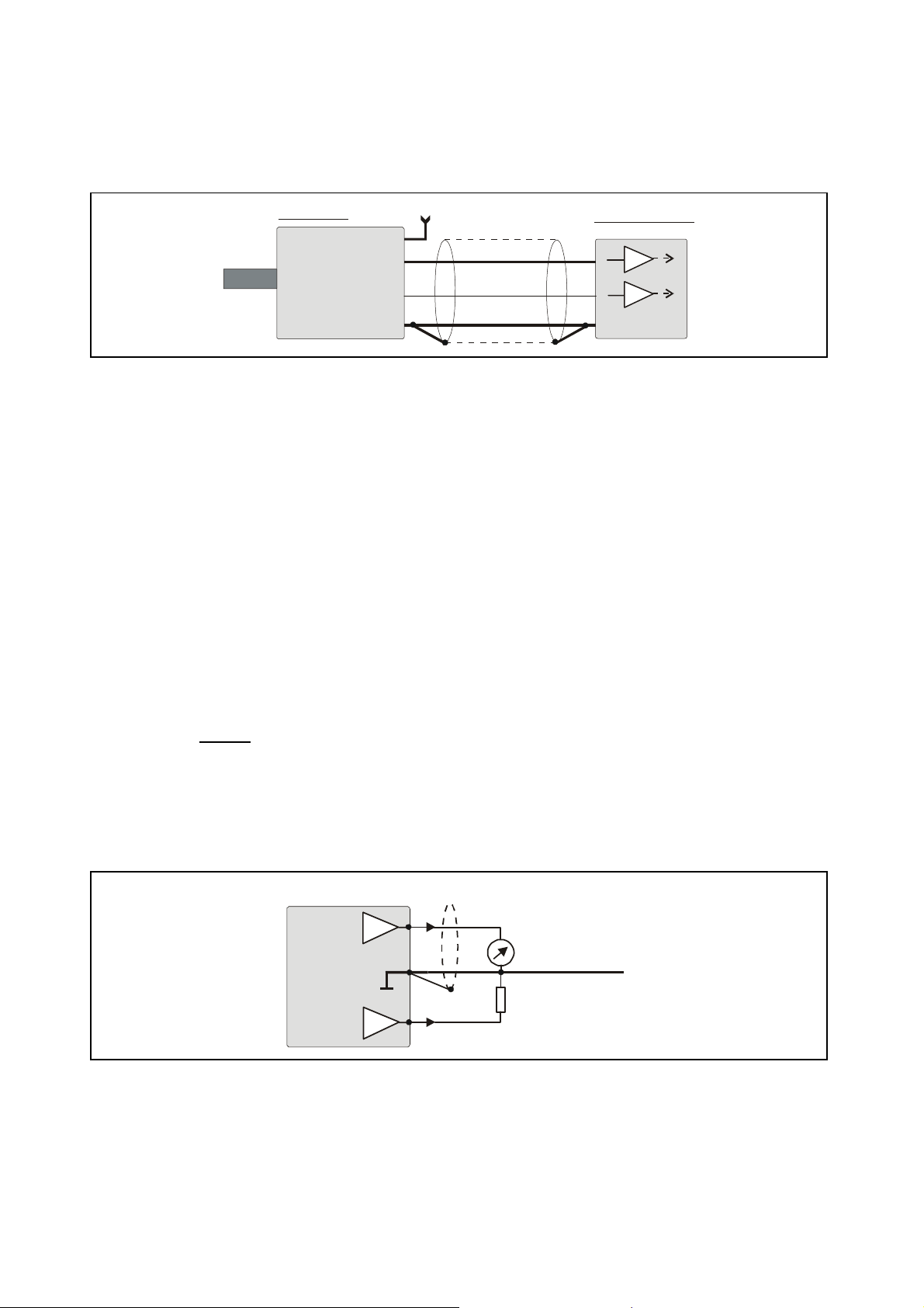
3.1. Incremental encoders TTL / RS 422
If applicable, the encoder can be supplied from the ZU251 converter. Where the encoder is
already supplied from a remote source, we recommend fully differential
GND connection between encoder and converter (see figures a. and b.)
TTL encoder
Screen
+
A
A
a)
B
B
-
TTL encoder
+ext
Screen
+
A
A
b)
B
B
-
operation, with no
ZU 251 converter
11 (+5.5V)
A
8
A
9
B
2
B
3
12 (GND)
ZU 251 converter
11 (+5.5V)
A
8
A
9
B
2
B
3
12 (GND)
ZU25102A_e.DOC / Mrz-08 Page 6 / 26
-ext
3.2. Incremental encoder HTL / 12-30V
The encoder may be supplied from the same source as the converter, or from another source.
HTL encoder
+24V
+
A
Screen
ZU 251 converter
9
B
GND
3
12 (GND)
3.3. Proximity switches, photocells etc.
This connection is fully similar to a HTL incremental encoder. With single-channel operation,
input B remains unconnected or can be used to select the output polarity. With use of two
independent counting events for forming the sum or the difference, input B operates as the
second counting input.
For use of sensors providing 2-wire NAMUR characteristics:
• Set the inputs to HTL and NPN
• Connect the positive wire of the sensor to the corresponding input and the negative
wire to GND.
3.4. Analogue outputs
The unit provides a +/-10V voltage output and a 0-20 mA / 4-20 mA current output at a
resolution of 14 bits, i.e. the voltage output operates in steps of 1.25 mV and the current output
operates in steps of 2.5 μA. The nominal load of the voltage output is 2 mA, the current output
accepts loads between 0 Ohms and 270 Ohms.
The analogue ground uses a separate terminal, which however internally is connected to the
GND potential of the power supply.
Screen
Vout
4
1
GND
Iout
7
+/- 10V
20 mA
(Imax = 2 mA)
(R = 0 - 270 Ohms)
ZU25102A_e.DOC / Mrz-08 Page 7 / 26
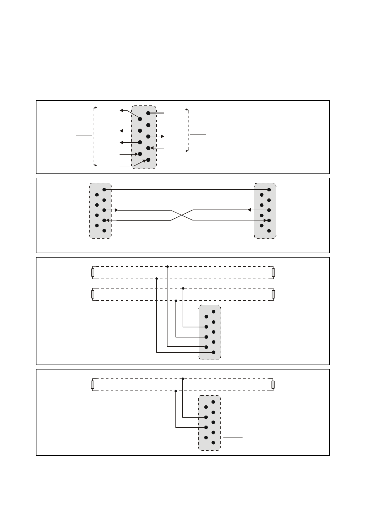
3.5. Serial interfaces
The unit provides a RS232 interface and a RS485 interface, however only one of the two can be
used at a time. Serial communication allows to read out the counting result and to set
parameters and variables by PC, according to need.
+5V
9
RS485
T+
T-
R+
8
7
6
R-
GND
5
5
9
9
4
4
8
8
3
3
7
7
6
6
1
1
TxD
2
2
RxD
RS232:
PC
T+
120 Ohms 120 Ohms
120 Ohms 120 Ohms
TR+
R-
GND int.
5
4
TxD
3
RxD
2
RS232
Sub-D-9 (female on unit site)
1
Please connect only pins 2, 3 and 5 !
9
9
8
8
7
7
6
6
ZU 251
5
5
4
4
3
3
2
2
1
1
5
5
9
9
4
T+
T-
RS485- Bus
( 4- wire )
120 Ohms
R+
R-
T+
T-
RS485- Bus
( 2- wire )
4
8
8
3
3
7
7
2
2
1
1
ZU 251
6
6
120 Ohms
5
5
9
9
4
4
8
8
3
3
7
7
2
2
1
1
ZU 251
6
6
ZU25102A_e.DOC / Mrz-08 Page 8 / 26
 Loading...