

Page 1
control – motion – interface
Series SD / SA / SR 330 - 644
Advanced Measurement of RPM, Speeds,
Baking and Processing Times, Speed Ratios,
Sum or Differential Speeds
motrona GmbH
Zwischen den Wegen 32
78239 Rielasingen - Germany
Tel. +49 (0)7731-9332-0
Fax +49 (0)7731-9332-30
info@motrona.com
www.motrona.com
Series SD: 4 programmable presets and outputs, RS 232 interface
Series SA: 4 programmable presets and outputs, RS 232 interface and analogue output
Series SR: 4 programmable presets and outputs, RS 232 interface and RS485 interface
Simultaneous measuring of two independent speeds by means of incremental
encoders, proximity switches or photocells
Two encoder inputs for use with 1 or 2 or 4 channels (A, /A, B, /B), each with
1 MHz of counting capability and individual scaling
Selectable operating modes for RPM, speed, baking time (reciprocal speed),
summing or differential speed, speed ratios and percentaged difference
4 speed presets with high-speed power transistor outputs
Models with relay outputs or front thumbwheel switches are available
Operating Instructions
SD34002g_e.doc / Sep-13 Page 1 / 60
Page 2

Safety Instructions
Version:
Description:
SD34002a/Mrz10/af/hk
First final sales version
SD34002b/Dez11
/sm
conformation
of the type designation
SD3
4
002c/Feb12/sm
Correction of the parameter
-
values and code listings
.
S
D34002
d/June12/pp
Corrected images in chapter 1 and 8.2
S
D34002e
/
Sept
12/pp
Correction of examples
for parameter
F06.075
SD34002f/Jan13/af/nw
Correction of parameter
F03.030, F04.042
and F06.066
SD34002g/
Sept
13/tj/nw
Extension: Advice for encoder inputs
This manual is an essential part of the unit and contains important hints about
function, correct handling and commissioning. Non-observance can result in
damage to the unit or the machine or even in injury to persons using the
equipment!
The unit must only be installed, connected and activated by a qualified electrician
It is a must to observe all general and also all country-specific and application-
specific safety standards
When this unit is used with applications where failure or maloperation could cause
damage to a machine or hazard to the operating staff, it is indispensable to meet
effective precautions in order to avoid such consequences
Regarding installation, wiring, environmental conditions, screening of cables and
earthing, you must follow the general standards of industrial automation industry
- Errors and omissions excepted –
General instructions for cabling, screening and grounding can be found in the
SUPPORT section of our website http://www.motrona.com
Parameter listing for SD/SA/SR x3x added.
SD34002g_e.doc / Sep-13 Page 2 / 60
Page 3

Table of Contents
1. Available Models................................................................................................................4
2. Introduction.........................................................................................................................6
3. Electrical Connections.........................................................................................................7
3.1. Power Supply................................................................................................................................9
3.2. Auxiliary Outputs for Encoder Supply ..........................................................................................9
3.3. Impulse Inputs for Incremental Encoders.....................................................................................9
3.4. Control Inputs Cont.1 – Cont.4.....................................................................................................9
3.5. Switching Outputs K1 – K4 ........................................................................................................10
3.6. Serial Interface ...........................................................................................................................10
3.7. Fast Analogue Output (SA models only) ....................................................................................10
4. Operating Modes of the Counter....................................................................................... 11
4.1. “Single Mode” (encoder 1 only): F02.004 = 0............................................................................13
4.2. Dual Mode (encoder1 and encoder 2 independently): F02.004 = 1...........................................14
4.3. Sum Mode (encoder 1 + encoder 2): F02.004 = 2 ......................................................................15
4.4. Differential Mode (encoder 1 - encoder 2): F02.004 = 3............................................................16
4.5. Product of Two Speeds (encoder 1 x encoder 2): F02.004 = 4...................................................17
4.6. Ratio of two Speeds: F02.004 = 5 or 6.......................................................................................18
4.7. Percentaged Speed Difference: F02.004 = 7 or 8 ......................................................................19
5. Keypad Operation ............................................................................................................. 20
5.1. Normal Operation .......................................................................................................................20
5.2. General Setup Procedure............................................................................................................20
5.3. Direct Fast Access to Presets.....................................................................................................21
5.4. Change of Parameter Values on the Numeric Level..................................................................22
5.5. Code Protection against Unauthorized Keypad Access.............................................................23
5.6. Return from the Programming Levels and Time-Out Function ..................................................23
5.7. Reset all Parameters to Factory Default Values........................................................................23
6. Menu Structure and Description of Parameters ................................................................24
6.1. Summary of the Menu................................................................................................................24
6.2. Description of the Parameters ...................................................................................................27
7. Practical Examples for Setup and Scaling .........................................................................44
7.1. Settings for the Example a) of Chapter 4.1 (Speed Display) .....................................................44
7.2. Settings for the Example b) of Chapter 4.1 (Baking Time).........................................................44
7.3. Settings for Example "Differential Speed" of Chapter 4.4 ........................................................45
7.4. Example for Use of the Filter......................................................................................................46
8. Appendix for models SD/SA/SR 6xx ................................................................................. 47
8.1. Relay Outputs .............................................................................................................................47
8.2. Front Thumbwheel Switches......................................................................................................47
8.3. Specific Parameters for Units with Thumbwheel Switches......................................................48
9. Appendix: Serial Communication Details ..........................................................................50
9.1. Setup of the Counter by PC ........................................................................................................50
9.2. Automatic and Cyclic Data Transmission ..................................................................................51
9.3. Communication Protocol.............................................................................................................51
9.4. Serial Register Codes .................................................................................................................53
10. Specifications ...................................................................................................................58
11. Dimensions.......................................................................................................................59
SD34002g_e.doc / Sep-13 Page 3 / 60
Page 4

1. Available Models
A = display, RS232 interface and analogue output
R = display, RS232 interface and RS485 interface
2 = two thumbwheel sets (4 decades each) *)
4 = four thumbwheel sets (4 decades each) *)
SD 340
The speed meters of this series include a range of models with similar functions and properties,
but with different housings, outputs and interfaces.
All models are equipped with 4 programmable presets and 4 fast-switching transistor outputs
as well as a serial RS232 interface.
SD models provide this basic configuration only.
SA models provide an additional high-speed analogue output
SR models provide an additional RS485 communication interface
All further properties of the models are fully identical. The range of available models also
includes units with relay outputs and front thumbwheel switches.
The following table explains the details of type designation and the possible options:
S = speed meter
D = display and RS232 interface
3 = housing 96 x 48 mm (3.780 x 1.890’’)
and 4 high-speed transistor outputs
6 = housing 96 x 96 mm (3.780 x 3.780’’)
with 4 high-speed transistor outputs
and 4 relay outputs
0 = no thumbwheel switches on front
*) Other combinations are possible, see section 8.2
SD34002g_e.doc / Sep-13 Page 4 / 60
Page 5

The following models are available:
SD 340, SA 340, SR 340
SD 640, SA 640, SR 640
SD 642, SA 642, SR 642
SD 644, SA 644, SR 644
Number and combination of front thumbwheels according to customer specification, see section 8.2
SD34002g_e.doc / Sep-13 Page 5 / 60
Page 6

2. Introduction
Speed meters of series SD, SA and SR have been designed to close a gap with multiple speed
measuring applications, which cannot be accomplished by normal industrial tachometers.
A continual demand for increasing production speeds and higher precision at the same time
results in counting frequencies exceeding the conventional frequency range.
Particularly with fast running machines it is most important to also get fast response of the
switching outputs or the analogue output.
Many applications require to evaluate the signals of two incremental measuring systems, and
to compare the results with respect to the sum or the difference or the ratio of the two speeds.
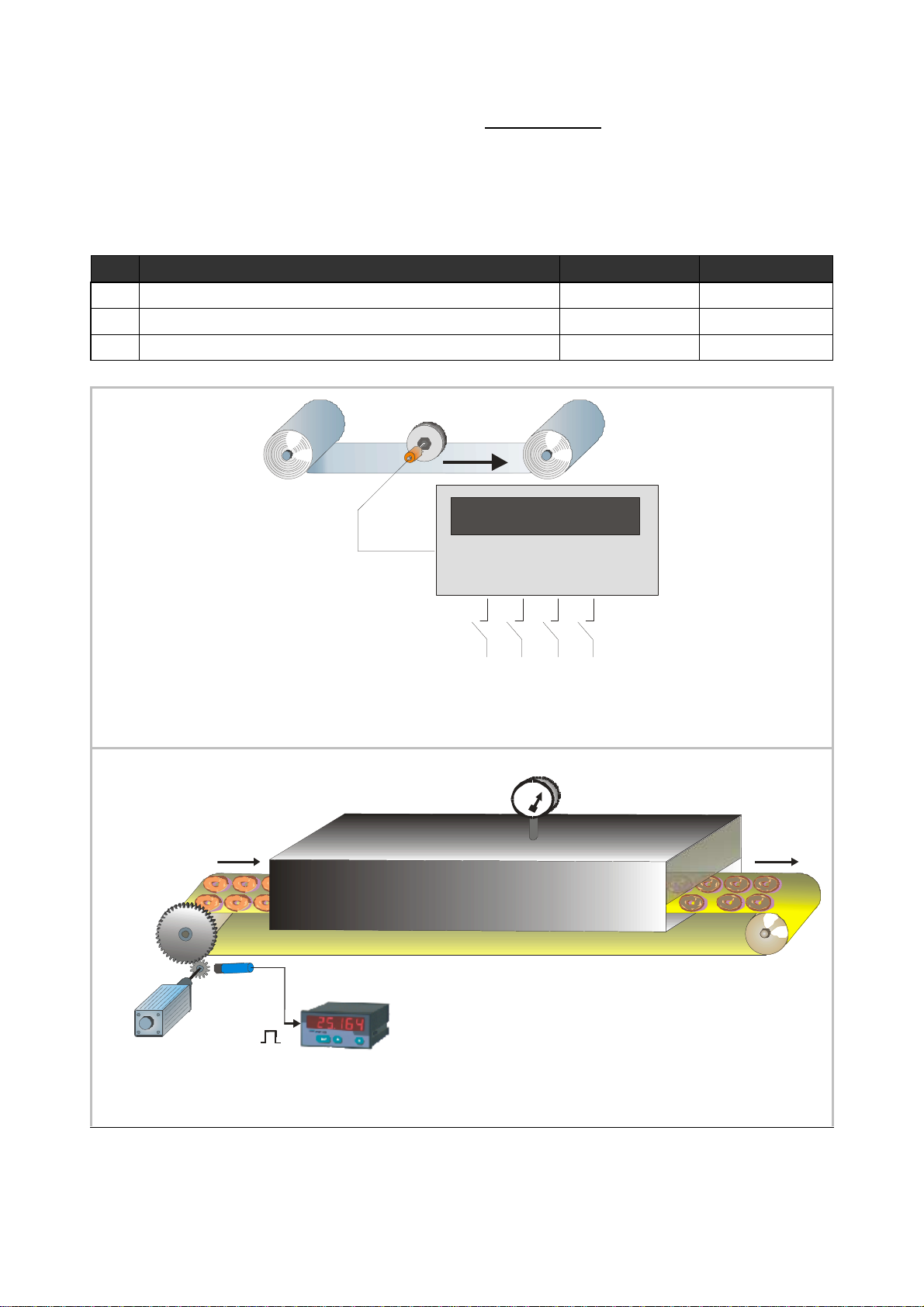
The latter is e.g. required to indicate the diameter of a winding roll by sensing the line speed
and the roll rpm.
Other applications with food processing or process technology need to record the speed in a
reciprocal way (i.e. baking or processing time calculated from the actual speed)
And still there exist applications where the use of traditional thumbwheel switches offers real
advantages compared to keypad and menu operations.
These are some of the reasons why the new indicator series SD / SA / SR have been designed.
This manual at first provides all basic instructions for operation of the
counter models presented in the previous chapter
For operation of relay outputs and thumbwheel switches (if applicable)
please observe the supplementary instructions given in the appendix
For easy PC setup and PC communication with SD and SA counters,
please use our “OS32” operator software (free of charge, download from
our homepage www.motrona.com
Where you like to have free serial access to the unit by PLC or IPC or by a
remote operator terminal, please observe the serial protocol details
described in our separate manual “Serpro”
Subsequently the manual uses the expression SD340 as a replacement for
all available models. However, statements are fully valid for the other
models too, except where especially remarked.
SD34002g_e.doc / Sep-13 Page 6 / 60
Page 7

3. Electrical Connections
2728293031
32
131415
16
G
NDG
NDG
NDG
NDG
N
D
+Vi
n+5
,
2
Vaux.
o
ut+
5,2
V
a
ux.
o
u
t+2
4
V
a
ux.ou
t
+
2
4
V
a
ux.
o
utE
nco
d
er2BE
nco
d
er2AE
n
cod
e
r
1
B
E
n
cod
e
r
1
AEnco
d
er1
/
A
E
n
cod
er1
/
B
E
n
cod
e
r
2/A
E
n
cod
e
r
2/BK2outK
1ou
t
K
3
o
u
tK4
o
u
t
Con
t.4Co
nt.
3
I
nte
r
fac
e
2*)Inte
r
fac
e
1*)Rx
D
(RS23
2)P
ROG
-
+
24 V DC
Power supply
Com+ (K1 - K4)
0V, GND
PROG
182423201922211112
272830331
17
4
29
26
25
32216
Interface 2 *)
Series "SD"
Series "SA"
Series "SR"
*) Interface 1:
*) Interface 2:
1 2 3 4 5 6 7 8 9 10
X1
18 19 20
17
X2
Encoder1*
*) Example shows wiring
for encoders with 5 volts
power supply and RS422
line driver output
Encoder 2*
Digital
Control
Inputs
21
+24
+24
Cont1
Cont2
Cont3
Cont4
23
+5
/A
/B
+5
/A
/B
11 12
25 26
24
Cont. 1
Cont. 2
TxD (RS232)
Com+ (K1-K4)
A
8
B
7
-
A
6
B
5
-
10
15
9
K1 out
K2 out
K3 out
K4 out
Fast
transistor
outputs
Interface 1 *)
RxD
RS232
TxD
GND
14
1
13
24 V AC
- n.c. - Analogue output 0/4 - 20 mA RS 485, B (-)
- n.c. - Analogue output +/- 10 V RS 485, A (+)
SD34002g_e.doc / Sep-13 Page 7 / 60
Page 8

Terminal
Name
Function
01
GND
Common Ground Potential (0V)
02
+5,2V out
Aux. output 5.2V/150 mA for encoder
supply
03
+24V out
Aux. output 24V/120 mA for encoder
supply
04
GND
Common Ground Potential (0V)
05
Encoder 2, /B
Encoder 2, chann
el /B (B inverted)
06
Encoder 2, /A
Encoder 2, channel /A (A inverted)
07
Encoder 1, /B
Encoder 1, channel /B (B inverted)
08
Encoder 1, /A
Encoder 1, channel /A (A inverted)
09
K4 out
Output K4, transistor PNP 30 volts, 350 mA
10
K3 out
Output K3, tr
ansistor PNP 30 volts, 350 mA
11
Cont.4
Digital control input
12
Cont.3
Digital control input
13
(PROG)
(for download of new firmware only, not for general use)
14
RxD
Serial RS232 interface, input (Receive Data)
15
Interface 1
16
17
+Vin
Power supply input, +17
–
40 VDC or 24 VAC
18
+5,2V out
Aux. output 5,2V/150 mA for encoder
supply
19
+24V out
Aux. output 24V/120 mA for encoder
supply
20
GND
Common Ground Potential (0V)
21
Encoder 2, B
Encoder 2, channel B (non
-
inverted
)22Encoder 2, A
Encoder 2, channe
l A (non
-
inverted
)23Encoder 1, B
Encoder 1, channel B (non
-
inverted
)24Encoder 1, A
Encoder 1, channel A (non
-
inverted
)25K2 out
Output K2, transistor PNP 30 volts, 350 mA
26
K1 out
Output K1, transistor PNP 30 volts, 350 mA
27
Cont.2
Digital cont
rol input
28
Cont.1
Digital control input
29
Com+ (K1
-
K4)
Common positive input for transistor outputs K1
-K430
TxD
Serial RS232 interface, output (Transmit Data)
31
GND
Common Ground Potential (0V)
32
GND
Common Ground Potential (0V) for DC or AC pow
er supply
Interface 2
SD 340: n.c. (no function)
SA 340: Analogue current output 0/4 - 20 mA
SR 340: Serial RS385 interface, line B (-)
SD 340: n.c. (no function)
SA 340: Analogue voltage output +/- 10 V
SR 340: Serial RS485 interface, line A (+)
*) 120 mA and 150 mA are per encoder, i.e. total maximum currents are 240 mA and 300 mA
SD34002g_e.doc / Sep-13 Page 8 / 60
Page 9

3.1. Power Supply
The SD340 counter accepts both, a 17 – 40 volts DC power or a 24 volts AC power (+/-10%)
for supply via terminals 17 and 1. The current consumption depends on the level of the input
voltage and some internal conditions; therefore it can vary in a range from 100 – 200 mA
(aux. currents taken from the unit for encoder supply not included).
3.2. Auxiliary Outputs for Encoder Supply
Terminals 2 and 18 provide an auxiliary output with approx. +5.2 volts DC (300 mA totally).
Terminals 3 and 19 provide an auxiliary output with approx. +24 volts DC (240 mA totally)
3.3. Impulse Inputs for Incremental Encoders
All input characteristics of the impulse inputs can be set by the parameter menu, for each of
the encoders separately. Depending on the application the unit can accept single channel
information (input A only without direction signal) or dual channel signals (A = step and B =
direction) or quadrature information (A / B, 90°). The following settings are possible:
Symmetric input (differential A, /A, B, /B) according to RS422 standard
TTL inputs at a level of 3.0 to 5 volts (differential, with inverted signal)
TTL inputs at a level of 3.0 to 5 volts (single-ended) *)
HTL signals at a 10 – 30 volts level
(alternatively differential with inverted signals A, /A, B, /B, or single-ended A, B only)
Impulses from photocells or proximity switches etc. providing a HTL level (10 – 30 volts)
Proximity switches according to NAMUR (2-wire) standard
(may need additional remote resistor)
*) requires special settings of the threshold parameters, see “Special parameters F08”
All encoder input lines are internally terminated by pull-down resistors ( 8,5 kΩ ).
Where encoders with pure NPN outputs are used, corresponding pull-up resistors must be
available inside the encoder or externally to ensure proper function (1 kΩ ... 3,3 kΩ).
3.4. Control Inputs Cont.1 – Cont.4
These inputs can be configured for various remote functions as described under 6.2.4.
All control inputs require HTL level. They can be individually set to either NPN (switch to -) or
PNP (switch to +) characteristics. For applications where edge-triggered action is needed, the
menu allows to set the active edge (rising or falling). Control inputs also accept signals with
Namur (2-wire) standard.
For reliable operation the minimum pulse width on the control inputs should be 50 µsec.
SD34002g_e.doc / Sep-13 Page 9 / 60
Page 10

3.5. Switching Outputs K1 – K4
RS 232
RS 485
SD340 provides four presets and outputs with programmable switching characteristics.
K1 – K4 are fast-switching and short-circuit-proof transistor outputs with a switching capability
of 5 – 30 volts / 350 mA each. The switching voltage of the outputs must be applied remotely
to the Com+ input (terminal 29)
3.6. Serial Interface
The serial RS232/RS485 interfaces can be used for the following purposes:
Set-up of the unit by PC (if desirable), by means of the OS32 PC software
Change of parameters during operation
Readout of actual counter or other values by PLC or PC
The figure below explains how to connect the SD340 unit and a PC using the standard Sub-D-9
serial connector, and how to connect the RS485 terminals to a PLC.
Details about serial communication are shown in chapter 9.
SD 340
SA 340
SR 340
14
30
31
16
SR 340
15
Where both, RS232 and RS485 interface are in use, you can communicate by the one or
by the other, but not by both interfaces at the same time
RxD RxD
TxDTxD
GND
Screen
A(+)
B(-)
2
PC
3
(Sub-D-9)
5
A
PLC
B
3.7. Fast Analogue Output (SA models only)
An analogue output is available with all SA models, providing a voltage output of +/- 10 volts
(Load = 2 mA), and a current output of 0 – 20 mA or 4 – 20 mA (load = 0 – 270 Ohms). All output
characteristics like beginning of conversion range, output swing etc. are freely programmable
via menu. The response time of the analogue output depends on the mode of measuring and
the sampling times used. The analogue resolution is 14 bits.
Please note that extensive serial communication with the unit may temporary increase the
analogue response time.
SD34002g_e.doc / Sep-13 Page 10 / 60
Page 11

4. Operating Modes of the Counter
For best survey, all parameters of the unit are arranged in 13 expedient groups, named
“F01” - “F13”. Depending on the application, only a few of these groups may be important,
while all other groups may be irrelevant for your specific application.
All details about configuration and function of the parameters can be founds in chapter 6.
Practical examples for settings are shown in chapter 7.
This section describes possible applications and operating modes of the unit.
The operation mode can be set under parameter group F02, parameter # F02.004.
It is possible to cycle the display between all reading modes shown in the following
function tables, by pressing one of the front keys or by using one of the control inputs
(you must have assigned the "display scrolling function" to one of the keys or the
inputs under menu F05 to activate the scrolling of the display).
LED L1 (red) and L2 (yellow) indicate which of the values is actually visible in display
L1 on: the speed of encoder 1 is displayed
L2 on: the speed of encoder 2 is displayed
L1 and L2 on: the combined value [encoder1]*[encoder2] is displayed.
LEDs shining continuously indicate: actual measuring value.
LEDs blinking slowly indicate: minimum value
(since last reset of the min/max memory).
LEDs blinking fast indicate: maximum value (since last reset of the min/max memory).
Scrolling of the display from one reading mode to another will not affect the function
of the preselection outputs K1 – K4
The analogue output (models SA) can be assigned to any of the readings accessible in
the display, by a special parameter. Scrolling of the display from one reading mode to
another will not affect the analogue output.
With all operating modes the evaluation of the input frequencies occurs fully
separately with use of individual scaling factors. Please observe that only integer
results after the scaling operations, but no decimal positions will appear in the
display. Where you like to display your result with decimals, please scale your value
correspondingly higher (by factor 10, 100 or 1000) and then use a decimal point to
receive the desired display value (see examples under 7.1)
With all encoders providing information about the direction of rotation
(e.g. quadrature encoders A/B/90°), the unit will also display a sign (positive with
A leading B and negative with B leading A). Preselection values can be set for
response to absolute values only (no consideration of the actual sign), or for response
to the signed value. With models SA the analogue output will also change the
+/- polarity in accordance with the actual sign.
All combinations [encoder1] * [encoder2] are calculated straightaway according to the
individual operating mode and the scaling factor of each channel. Please take care
that the results to combine are scaled with proper and compatible dimensions
(don't compare apples and oranges)
SD34002g_e.doc / Sep-13 Page 11 / 60
Page 12

You can choose from the following operating modes:
Operating Mode
0
Single mode, evaluation of encoder 1 only
1
Dual mode, individual evaluation of encoder 1 and encoder 2
2
Sum mode, [speed of encoder1] + [speed of encoder2]
3
Differential mode, [speed of encoder1]
-
[speed of encoder2]
4
Multipl
ication mode, [speed of encoder1] x [speed of encoder2]
5
Ratio mode, [speed of encoder1] : [speed of encoder2]
6
Inverse ratio mode, [speed of encoder2] : [speed of encoder1]
7
Percentage mode, [encoder1
-
encoder2] : [encoder2] x 100%
8
Inverse perce
ntage mode, [encoder2
-
encoder1] : [encoder1] x 100%
Measuring Function of the unit
F02.004
Your choice of operating mode will decide how in general the two encoder frequencies have to
be treated. It will not affect the scaling or the measuring characteristics or the final
presentation of the result.
SD34002g_e.doc / Sep-13 Page 12 / 60
Page 13
4.1. “Single Mode” (encoder 1 only): F02.004 = 0
Display
L1 (red)
L2 (yellow)
1
Actual measuring value of encoder 1
statically ON
--2Minimum value since last min/max reset
blinking slow
--3Maximum value s
ince last min/max reset
blinking fast
--
motor
Only the inputs of encoder 1 are active, signals on the encoder 2 inputs will not be evaluated.
Besides the actual counter value, the unit also records minimum and maximum values, with
regard to the last Reset of the Min/Max memory.
All 4 presets are related to the actual measuring value.
Measuring wheel
Encoder
f1
Encoder 1
Example a): Measuring of RPM or speed *)
Tunnel furnace
- 3 4 5 6
Cont.1
Remote control signals
°C
Cont.4
Encoder 2
Proximity
sensor
Speed-variable
Example b): Measuring of baking time or processing time (reciprocal speed) *)
*) For these applications you can find concrete examples of parameter settings in chapter 7.
SD34002g_e.doc / Sep-13 Page 13 / 60
Calculated baking time
Page 14

4.2. Dual Mode (encoder1 and encoder 2 independently): F02.004 = 1
Display
L1 (red)
L2 (yellow)
1
Actual measuring value of encoder 1
statically ON
2
Minimum value encoder 1 since last min/max reset
blinking slow
3
Maximum value encoder 1 since last min/max reset
blinking fast
4
Actual measuring value of encoder 2
statically ON
5
Minimum value encoder 2 since last min/max reset
blinking slow
6
Maximum value encoder 2 since last min/max reset
blinking fast
Remote control functions
Both, encoder input 1 and encoder input 2 are active and the frequencies are evaluated
independently,
Besides the actual measuring values the unit also records the minimum and maximum values of
both channels, with regard to the last Reset of the Min/Max memory.
Presets K1 and K2 refer always to the measuring result of encoder 1.
Presets K3 and K4 refer always to the measuring result of encoder 2.
-
-
-
1 2 3 4 5 6
Geber 1
Cont.1
Example: Dual speed application with selectable display of motor speed (rpm) and product throughput (p)
Cont.4
Geber 2
Products per minute (p)Motor speed (rpm)
SD34002g_e.doc / Sep-13 Page 14 / 60
Page 15

4.3. Sum Mode (encoder 1 + encoder 2): F02.004 = 2
Display
L1 (red)
L2 (ye
llow)
1
Actual sum [speed encoder1] + [speed encoder2]
statically ON
statically ON
2
Minimum sum value since last min/max reset
blinking slow
blinking slow
3
Maximum sum value since last min/max reset
blinking fast
blinking fast
4
Actual measuring valu
e of encoder 1
statically ON
---
5
Actual measuring value of encoder 2
---
statically ON
Both inputs, encoder 1 and encoder 2, are active. From both values the unit forms the sum, with
consideration of the individual scaling of each channel. The final result can once more be
scaled into user-friendly engineering units by means of the special scaling parameters in
parameter group F02.
Besides the actual speeds and the sum value, the unit also records minimum and maximum
values of the sum.
Preset K1 is related to the absolute speed of encoder 1.
Preset K2 is related to the absolute speed of encoder 2.
Presets K3 and K4 are related to the actual sum of the speeds (encoder 1 + encoder 2)
2 x incremental flow sensors
Q1
Q2
1 2 3 4 5 6
Encoder 1
Example: Summing flow Q1 + Q2 (liters per minute) of two incremental rotary flow sensors
Encoder 2
SD34002g_e.doc / Sep-13 Page 15 / 60
Page 16

4.4. Differential Mode (encoder 1 - encoder 2): F02.004 = 3
Display
L1 (red)
L2 (yellow)
1
Speed difference [speed encoder1]
-
[speed encoder2]
statically
ON
statically ON
2
Minimum difference since last min/max reset
blinking slow
blinking slow
3
Maximum difference since last min/max reset
blinking fast
blinking fast
4
Actual measuring value of encoder 1
statically ON
---
5
Actual measuring value of enc
oder 2
---
statically ON
Remote control functions
Both inputs, encoder 1 and encoder 2, are active. From both values the unit forms the
difference, with consideration of the individual scaling of each channel. The final result can
once more be scaled into user-friendly engineering units by means of the special scaling
parameters in parameter group F02.
Besides the actual speeds and the differential value, the unit also records minimum and
maximum values of the speed difference.
Preset K1 is related to the absolute speed of encoder 1.
Preset K2 is related to the absolute speed of encoder 2.
Presets K3 and K4 are related to the actual differential speed (encoder 1 - encoder 2)
speed 1
speed 2
- 3 4 .5 6
Encoder 1
Cont.1
Example: Differential speed of two belt conveyors
Encoder 2
Cont.4
SD34002g_e.doc / Sep-13 Page 16 / 60
Page 17

4.5. Product of Two Speeds (encoder 1 x encoder 2): F02.004 = 4
Display
L1 (red)
L2 (yellow)
1
Speed product [speed encoder1] x [speed encoder2]
statically ON
statically ON
2
Minimum product since last min/max reset
blinking slow
blinking slow
3
Maximum product sin
ce last min/max reset
blinking fast
blinking fast
4
Actual measuring value of encoder 1
statically ON
---
5
Actual measuring value of encoder 2
---
statically ON
v (speed)
W = 1/2 m v
Both inputs, encoder 1 and encoder 2, are active. Both speeds are multiplied to form the
product, with consideration of the individual scaling of each channel. The final result can once
more be scaled into user-friendly engineering units by means of the special scaling parameters
in parameter group F02.
Besides the actual speeds and the multiplication result, the unit also records minimum and
maximum values of the product.
Preset K1 is related to the absolute speed of encoder 1.
Preset K2 is related to the absolute speed of encoder 2.
Presets K3 and K4 are related to the product of both speeds (encoder 1 x encoder 2)
m
(mass)
2
Geber 1
Cont.1
Example: Direct measurement of the kinetic energy "W" of a moving body with the mass "m"
Geber 2
Cont.4
SD34002g_e.doc / Sep-13 Page 17 / 60
Page 18

4.6. Ratio of two Speeds: F02.004 = 5 or 6
Display
L1 (red)
L2 (yellow)
1
Speed ratio [encoder
] : [encoder
] *)
statically ON
statically ON
2
Minimum ratio since last min/max reset
blinking slow
blinking slow
3
Maximum rat
io since last min/max reset
blinking fast
blinking fast
4
Actual speed of encoder 1
statically ON
---5Actual speed of encoder 2
---
statically ON
Remote control functions
Both inputs, encoder 1 and encoder 2, are active. The unit calculates the ratio of the two
speeds, with consideration of the individual scaling of each channel. The final result can once
more be scaled into user-friendly engineering units by means of the special scaling parameters
in parameter group F02 (conversion factor K = F02.09 : F02.08), see figure below*).
F02.004 = 5 calculates [encoder1] : [encoder2]
F02.004 = 6 calculates [encoder2] : [encoder1]
Besides the actual speeds and the ratio the unit also records minimum and maximum values of
the ratio.
Preset K1 is related to the absolute speed of encoder 1.
Preset K2 is related to the absolute speed of encoder 2.
Presets K3 and K4 are related to the ratio of both speeds
(1 or 2)
f1 f2
1 2 3 4 5 6
Encoder 1
Cont.1
Cont.4
Encoder 2
(2 or 1)
d = K x
f
1
f2
d
Roll diameter
Example: Calculation of the roll diameter "d" from the ratio of infeed speed and roll rpm
*) The unit presents the ratio of the two speeds as an integer number only, e.g. if both speeds are equal,
the unit would just display "1". To display a ratio with decimal positions like 1.0 or 1.00 or 1.000 etc. it
is necessary to follow one of these hints:
a. scale the speed used as numerator by a factor of 10 or 100 or 1000 higher than the denominator, or
b. set parameters F02.009 (multiplier) and F02.008 (divider) with a ratio of 10, 100 or 1000
SD34002g_e.doc / Sep-13 Page 18 / 60
Page 19

4.7. Percentaged Speed Difference: F02.004 = 7 or 8
[ speed of encoder 1 ] -
[ speed ofencoder 2 ]
[ speed of encoder 2 ] -
[ speed ofencoder 1 ]
Display
L1 (red)
L2 (yellow)
1
Actual percentage difference
statically ON
statically ON
2
Minimum percentage since last min/max reset
blinking slow
blinking slow
3
Maximum percentage since last min/max reset
blinking fast
blinking fast
4
Actual speed
of encoder 1
statically ON
---5Actual speed of encoder 2
---
statically ON
Remote control functions
tension
speed 1
speed 2
speed 2 > speed1
Both encoder inputs "encoder1" and "encoder2" are active. With consideration of the individual
scaling of each channel the unit calculates the percentaged difference as shown below:
F02.004 = 7:
F02.004 = 8:
Display =
[ speed of encoder 2 ]
Display =
[ speed of encoder 1 ]
x 100%
x 100%
Parameter „Percent Format“ (F02.018) determines the number of decimal positions of the result:
0 = display range -999999 to + 9999999 % 1 = display range -99999,9 to +99999,9 %
2 = display range -9999,99 to +9999,99 % 3 = display range -999,999 to +999,999 %
The final percentage result can once more be scaled into user-friendly engineering units by
means of the special scaling parameters in parameter group F02
Besides the actual speeds and the ratio the unit also records minimum and maximum values of
the ratio.
Preset K1 is related to the absolute speed of encoder 1.
Preset K2 is related to the absolute speed of encoder 2.
Presets K3 and K4 are related to the percentaged difference of both speeds
Encoder 1
f
1
Cont.1
Example: stretching of material by building up tension
SD34002g_e.doc / Sep-13 Page 19 / 60
Encoder 2
Cont.4
f
2
Page 20

5. Keypad Operation
PROG
UP
DOWN
ENTER
An overview of all parameters and explanations can be found under section 6.
The menu of the unit uses four keys, hereinafter named as follows:
Key functions depend on the actual operating state of the unit. Essentially we have to describe
three basic states:
Normal operation
General setup procedure
Direct fast access to presets and set values
5.1. Normal Operation
In this mode the unit operates as a counter according to the settings defined upon setup. All
front keys may have customer-defined functions according to the specifications met in the
keypad definition menu F05 (e.g. scrolling of the display, Reset, Inhibit etc.)
5.2. General Setup Procedure
The unit changes over from normal operation to setup level when keeping the key down
for at least 2 seconds. Thereafter you can select one of the parameter groups F01 to F13.
Inside the group you can now select the desired parameter and set the value according to need.
After this you can either set more parameters or return to the normal operation.
The adjoining sequence of key operations explains how to change
Parameter number 060 of group F06 from the original value of 0 to 8
P
SD34002g_e.doc / Sep-13 Page 20 / 60
Page 21

Step
State
Key action
Di
splay
Comment
00 Normal operation Actual value
Display of the
Level:
Confirmation of F06.
Level:
F06.059…
Select parameter 060
Paramete
r 060 appears in
Level:
Setting has been modified
F06.060
Save the new setting (8)
Level:
F06
Return to level parameter
Level:
Actual value
Return to normal operation
Normal operation
01 > 2 sec. F01
Parameter group
02
03
04
05
06
07
08
09
10
Parameter group
Parameter numbers
Parameter values
Parameter numbers
Parameter groups
5 x F02 … F06 Select group # F06
F06.058
The first parameter of this
group is F06.058
2 x
F06.060
0
display, actual setting is 0
8 x 1 …. 8
from 0 to 8
groups
During the general setup procedure all counter activities remain
disabled. New parameter settings become active after return to
normal operation only.
5.3. Direct Fast Access to Presets
To get to the fast access routine, please press both
and
This will access the parameter group F01 right away. To change of the settings follow the same
procedure as already described above. Besides the advantage of direct access, the fundamental
difference to general setup is the following:
During the fast access procedure all counter functions remain fully active.
Access is limited to presets; no other parameters can be changed.
at the same time
SD34002g_e.doc / Sep-13 Page 21 / 60
Page 22

5.4. Change of Parameter Values on the Numeric Level
PROG
UP
DOWN
ENTER
Saves the actual value
Increments the
Decreme
nts the
Shifts the cursor (blinking
Step
Display
Key action
Comment
00102
4
Display of actual parameter setting, last
4 x
Scroll last digit down to 0
00102
0
Shift cursor to left
0010
2
0
2 x
Scroll highlighted digit down to 0
0010
0
0
Shift curser 2 positions left
00
1
000
Scroll high
lighted digit down to 0
00
0
000
Shift cursor left
000000
5 x
Scroll highlighted digit up to 5
050000
Shift cursor left
0
50000
2 x
Scroll highlighted digit up to 2
2
50000
Save new setting and return to the
The numeric range of the parameters is up to 6 digits. Some of the parameters may also include
a sign. For fast and easy setting or these values the menu uses an algorithm as shown
subsequently. During this operation the front keys have the following functions:
shown in the display and
returns to the parameter
selection level
With signed parameters the left digit scrolls from 0 to 9 and then shows “–„ (negative) and
“-1“ (minus one). The example below shows how to change a parameter from the setting 1024
to the new setting 250 000.
This example assumes that you have already selected the parameter group and the parameter
number, and that you actually read the parameter value in the display.
Highlighted digits appear on colored background.
00
01
02
03
highlighted
(blinking) digit
highlighted
(blinking) digit
digit is highlighted
digit) one position to the
left, or from utmost left
to right
04
05
06
07
08
09
10
SD34002g_e.doc / Sep-13 Page 22 / 60
2 x
parameter number level
Page 23

5.5. Code Protection against Unauthorized Keypad Access
Parameter group F07 allows to define an own locking code for each of the parameter menus.
This permits to limit access to certain parameter groups to specific persons only.
When accessing a protected parameter group, the display will first show “CODE” and wait for
your entry. To continue keypad operations you must now enter the code which you have stored
before, otherwise the unit will return to normal operation again.
After entering your code, press the ENTER key and keep it down until the unit responds.
When your code was correct, the response will be “YES” and the menu will work normally.
With incorrect code the response will be “NO” and the menu remains locked.
In order to avoid inadvertent misadjustment upon commissioning, parameter
groups F07 (keypad protection), F08 (special functions) and F11 (Linearization) are
already protected by factory setting. For access please use code 6078
5.6. Return from the Programming Levels and Time-Out Function
At any time the PROG key sets the menu one level up and finally returns to normal operation.
The same step occurs automatically via the time-out function, when during a period of 10
seconds no key has been touched.
Termination of the menu by automatic time-out will not store new settings, unless they have
already been stored by the PROG key after editing.
5.7. Reset all Parameters to Factory Default Values
Upon special need it may be desirable to set all parameters back to their original factory
settings (e.g. because you have forgotten your access code, or by too many change of settings
you have achieved a complex parameter state). Default values are indicated in the parameter
tables shown later.
To reset the unit to default, please take the following steps:
Switch power off
Press
Switch power on while you keep down both keys
Where you decide to take this action, please note that all parameters and
settings will be lost, and that you will need to run a new setup procedure
again.
and
simultaneously
SD34002g_e.doc / Sep-13 Page 23 / 60
Page 24
6. Menu Structure and Description of Parameters
K1 out
K2 out
K3 out
K4 out
High Speed
Switching Outputs
Analogue Output
(Models SA only))
P
ENT
F01
F06
F06
F07
F09
F11
F12
F13
All parameters are arranged in a reasonable order of functional groups (F01 to F13). Essential
settings appear right at the beginning and optional parameters are located towards the end of
the parameter list. You must only set those parameters which are really relevant for your
specific application. Unused parameters can remain like set by default.
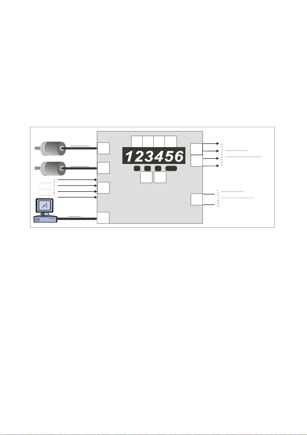
6.1. Summary of the Menu
This section shows a summary of the parameter groups, with an assignment to the functional
parts of the unit.
Digital
Control
Inputs
Encoder 1
Encoder 2
RS232
Cont1
Cont2
Cont3
Cont4
F03
F04
F05
F10
F02
up
dn
+/-10V
20 mA
High Speed
SD34002g_e.doc / Sep-13 Page 24 / 60
Page 25

F01 Preselections F04 Encoder 2 Properties
000 Preselection switchpoint K1 034 Encoder 2 properties
001 Preselection switchpoint K2 035 Counting direction up / down
002 Preselection switchpoint K3 036 Sampling Time 2
003 Preselection switchpoint K4 037 Wait Time 2
038 Filter 2
F02 Basic Settings 039 Input frequency 2
004 Mode of operation 040 Display value 2
005 Decimal point [encoder 1] 041 Display mode 2
006 Decimal point [encoder 2] 042 Set value 2
007 Decimal point [encoder 1]* [encoder 2] 043 Start-up delay 2
008 Divider (scaling factor) 044 Standstill definition 2
009 Multiplier (scaling factor)
010 Display mode F05 Key Commands and Control Inputs
011 Offset 046 Key UP
012 Brightness of display 047 Key DOWN
013 Update cycle time of display 048 Key ENTER
014 Number of sampling impulses 049 Control input 1, (characteristics)
015 Wait time for sampling 050 Control input 1 (function)
016 Synchronization encoder 1 / encoder 2 051 Control input 2, (characteristics)
017 Limitation of input frequency range 052 Control input 2 (function)
018 Percentaged display format 053 Control input 3, (characteristics)
054 Control input 3 (function)
F03 Encoder 1 Properties 055 Control input 4 (characteristics)
022 Encoder 1 properties 056 Control input 4 (function)
023 Counting direction up / down
024 Sampling Time 1 F06 Switching Characteristics of Outputs
025 Wait Time 1 058 K1 (static or timed switching)
026 Filter 1 059 K2 (static or timed switching)
027 Input frequency 1 060 K3 (static or timed switching)
028 Display value 1 061 K4 (static or timed switching)
029 Display mode 1 062 Hysteresis K1
030 Set value 1 063 Hysteresis K2
031 Start-up delay 1 064 Hysteresis K3
032 Standstill definition 1 065 Hysteresis K4
066 Preselection mode K1
067 Preselection mode K2
068 Preselection mode K3
069 Preselection mode K4
070 Output polarity (NO or NC)
071 Sign of Thumbwheel (SD6... only)
072 Thumbwheel assignment
073 Output locking upon power-up
074 Start-up delay
075 Self-retaining of outputs
SD34002g_e.doc / Sep-13 Page 25 / 60
Page 26

F07 Keypad Protection Codes F11 Range of Linearization
078 Code for F01 116 Linearization range encoder 1
079 Code for F02 117 Linearization range encoder 2
<---> <--->
089 Code for F13
F08 Special Functions F12 Linearization Table for Encoder 1
095 Encoder 1 trigger threshold 118 First interpolation point (x1, original value)
096 Encoder 2 trigger threshold 119 First interpolation point (y1, replacement)
<---> <--->
148 Last interpolation point (x16, original value)
149 Last interpolation point (y16, replacement)
F09 Analogue Output Definitions (SA only) F13 Linearization Table for Encoder 2
100 Output mode voltage / current 150 First interpolation point (x1, original value)
101 Conversion range, start value 151 First interpolation point (y1, replacement)
102 Conversion range, end value <---> <--->
103 Analogue span 180 Last interpolation point (x16, original value)
104 Analogue offset 181 Last interpolation point (y16, replacement)
105 Assignment of the analogue output
F10 Serial Communication
106 Serial unit address
107 Baud rate
108 Data format
109 Communication protocol
110 Timer for auto-transmit
111 Serial register code for transmission
112 Command “Set”
113 Command “Freeze”
114 Command “Hold”
SD34002g_e.doc / Sep-13 Page 26 / 60
Page 27

6.2. Description of the Parameters
F02.009
F02.008
F02.009
F02.008 x
6.2.1. Preselections and presets
F01 Range Default
F01.000 Preselection K1 -199 999 ... 999 999 1 000
F01.001 Preselection K2 -199 999 ... 999 999 2 000
F01.002 Preselection K3 -199 999 ... 999 999 3 000
F01.003 Preselection K4 -199 999 ... 999 999 4 000
F02 Range Default
F02.004 Operational Mode: 0 … 8 1
0 = Single mode, evaluation of encoder 1 only
1 = Dual mode, individual evaluation of encoder 1 and encoder 2
2 = Sum mode, [encoder1] + [encoder2]
3 = Differential mode, [encoder1] - [encoder2]
4 = Multiplication mode, [encoder1] x [encoder2]
5 = Ratio mode, [encoder1] : [encoder2]
6 = Inverse ratio mode, [encoder2] : [encoder1]
7 = Percentage mode, [encoder1 - encoder2] : [encoder2] x 100%
8 = Percentage mode, [encoder2 - encoder1] : [encoder1] x 100%
F02.005 Decimal Point 1: position of the decimal point with encoder 1 0 … 5 0
F02.006 Decimal Point 2: position of the decimal point with encoder 2 0 … 5 0
F02.007 Decimal Point 12: position of the decimal point with combinations
[encoder 1]* [encoder 2]
F02.008 Divider: reciprocal scaling factor for combined results 1 – 999 999 1000
F02.009 Multiplier: proportional scaling factor for combined results 1 – 999 999 1000
F02.010 Total Display Mode (re-scaling of combined encoder results): 0 ... 3 0
0= Proportional presentation of the combination value, no further
conversion
0 … 5 0
Combined display value =
[ ] [ ]encoder1 * encoder2 x
1= Reciprocal presentation of the combination value,
decimal format
Combined display value =
[ ] [ ]encoder1 * encoder2
2= See above, but reciprocal presentation of the combination
value with clock format 9999 min : 59 sec
3= See above, but reciprocal presentation of the combination
value with clock format 99 h : 59 min : 59 sec
F02.011 Offset: -199 999
This constant value will be finally added to the scaling result
(including sign)
...
+999 999
F02.012 Brightness of the 7-segment LED display 0 … 4 0
0= 100% of max. brightness
1= 80% of max. brightness
2= 60% of max. brightness
3= 40% of max. brightness
4= ..20% of max. brightness
0
SD34002g_e.doc / Sep-13 Page 27 / 60
Page 28
F02 Range Default
F02.013 Display Update Time:
0 - 100 0
0 = immediate display update after each result (fastest)
100 = timed update, approx. 1/sec (slowest)
F02.014 Sampling Pulses: *a)
0 – 30 000 0.50
Number of input impulses on channel A to calculate a
measuring result
With all settings >0 the function of the parameters
"Sampling Time" (F03.024 and F04.036) is disabled
F02.015 Wait Time Sampling:
0.01 - 99.99 sec 0
Time limit: if with use of parameter F02.014 the input pulses
should get interrupted, a result will be calculated and displayed
latest after elapse of this time limit
F02.016 Synchronization: *b)
0, 1 0
Synchronization of encoder1 / encoder2 measurement
0 = Synchronization OFF. Evaluation of encoder1/encoder2
happens fully independently and at different times
1 = Synchronization ON. Evaluation of encoder1/encoder2
is synchronized and happens at the same time
F02.017 Input Limitation: *c)
0 - 3 0
Limitation of the input frequency (digital low-pass filter)
0 = no limitation of the input frequency
1 = Limitation to 500 kHz max.(both encoder inputs)
2 = Limitation to 100 kHz max.(both encoder inputs)
3 = Limitation to 10 kHz max.(both encoder inputs)
F02.018 Percent Format: Decimal presentation of percentaged display 0 - 3 0
0 = Format +/-999999 % 1 = Format +/-99999,9 %
2 = Format +/-9999,99 % 3 = Format +/-999,999%
*) Important Hints:
a. With irregular and out-of-round motion-sequence it may be advantageous to use a
fixed number of input pulses for sampling, instead of a sampling time. This method
is suitable to stabilize or suppress undulation of the display (e.g. with unbalanced
and eccentric movements) because an overall average of one undulation is formed
b. It is advisable to always use the synchronized mode whenever measuring speed
ratios or percentaged speed difference. Otherwise unacceptable variation of the
display may occur, caused by the different timing of the two speed values
With the synchronization set to ON, parameters "Sampling Time1" (or "Sampling
Pulses") as well as "Wait Time1" are used conjointly for both encoders and the
corresponding settings for encoder 2 are inoperative. The response time of the unit
depends in each case on the lower one of the two input frequencies
c. Where the low-pass filter is used to limit the input frequency, higher frequencies
than indicated will no more be evaluated correctly
SD34002g_e.doc / Sep-13 Page 28 / 60
Page 29

6.2.2. Definitions for encoder 1
F03 Range Default
F03.022 Encoder Properties1: 0 … 5 1
0= Differential impulses A, /A, B, /B (2 x 90°) *)
1= Single-ended HTL impulses (10 - 30 V, format A, B, 2 x 90°)
2= Differential impulse input A, /A (count, step) *)
Differential signal B, /B (static direction signal)
3= Single-ended HTL impulse A (count, step)
Single-ended HTL signal B (static direction signal)
4= Differential impulse input A, /A only *)
5 Single-ended HTL impulse input A only
F03.023 Direction1: positive or negative speed (forward / reverse) 0 … 1 0
0= Positive speed when A leads B
1= Positive speed when A lags B
F03.024 Sampling Time1: 0.000**) … 9.999
Internal measuring time to evaluate the frequency
F03.025 Wait Time1: Maximum time to wait for the next input pulse
When after this waiting time no further impulse appears, the
sec.
0.01 … 99.99
sec.
frequency result is set to zero (f = 0)
F03.026 Filter1: Digital filter for smoothing unstable input frequencies
0 - 8 0
(for detailed explications see 7.4)
0= Filter OFF
(very fast response to changes in frequency)
1= Floating average over the last 2 measuring cycles
2= Floating average over the last 4 measuring cycles
3= Floating average over the last 8 measuring cycles
4= Floating average over the last 16 measuring cycles
5= Exponential filter, Τ (63%) = 2 x Sampling Time
6= Exponential filter, Τ (63%) = 4 x Sampling Time
7= Exponential filter, Τ (63%) = 8 x Sampling Time
8= Exponential filter, Τ (63%) = 16 x Sampling Time
(very slow response to changes in frequency)
F03.027 Input Value1: Typical input frequency of the application (Hz) for
use as a scaling reference for the display
F03.028 Display Value1: Desired display value
1 - 999 999
Hz
1 - 999 999 1000
This numeric value appears in the display when the reference
frequency is applied to the input (as set under "Input Value")
0.001
1.00
1000
*) this is valid for any kind of differential input signal (i.e. signal + inverted signal),
no matter if RS422 or TTL or HTL level
**) minimum sampling time at 0.000 (<1ms)
SD34002g_e.doc / Sep-13 Page 29 / 60
Page 30

F03 Range Default
F03.029 Display Mode1: Measuring characteristics of the display *) 0 - 3 0
0= Proportional characteristics
Suitable for measurement of rpm, speed and frequency
The display value is proportional to the input frequency "f".
Display =
f (Hz) x F03.028
F03.027
1= Reciprocal characteristics, decimal format 999999
Suitable for measurement of baking times, through-put
time and other processing times
The display value is inversely proportional to the
input frequency "f"
Display =
F03.028 x F03.027
f (Hz)
2= Reciprocal, clock format 9999 min : 59 sec **)
otherwise all similar to setting 1
3= Reciprocal, clock format 99 h : 59 min : 59 sec **)
otherwise all similar to setting 1
F03.030 Set Value1: Preset value to simulate fixed input frequency -199 999
When you have assigned the function "Set Frequency 1" to any of
the front keys or the control inputs (see parameter group F05),
999 999 (x.xx Hz)
...
then this function can be used to temporary substitute the real
input frequency of encoder 1 by a virtual frequency according to
setting. This e.g. allows simulation of the unit and all functions /
outputs while the machine itself is in standstill. When the Set
Value1 is set to 2000 the frequency value corresponds to 20.00
Hz.
0
*) Practical setting examples for these display modes can be found in chapter 7.
**) For setup and scaling of the unit please always use decimal format first and
set your display to full seconds. When you find that all other functions work fine, then
change over to the desired clock format.
SD34002g_e.doc / Sep-13 Page 30 / 60
Page 31

F03 Range Default
F03.031 Start-up Mode1: Start-up delay for the switching outputs *) 0 ... 10 0
The start-up delay is suitable to temporary suppress the control function
of a switching output (in general for monitoring of a minimum value).
The machine then is allowed to start up first, prior to activation of the
alarm. The start-up delay becomes active upon power-up of the unit or
after the unit has detected "standstill".
The following settings are available (always for encoder 1):
0 = Start-up delay OFF
1 = timed delay: 001 second
2 = timed delay: 002 seconds
3 = timed delay: 004 seconds
4 = timed delay: 008 seconds
5 = timed delay: 016 seconds
6 = timed delay: 032 seconds
7 = timed delay: 064 seconds
8 = timed delay: 128 seconds
9 = automatic delay until first exceeding of the minimum value
10 = external suppression by means of a control input
F03.032 Standstill Time1: Time for definition of "standstill" of encoder 1 0.00 ... 99,99
After the unit has detected "frequency = 0" (see parameter "Wait
sec.
0.00
Time1"), the unit will continue waiting until "Standstill Time1" has
elapsed and then finally report "standstill of encoder 1".
*) When you use the start-up delay function with combined modes [encoder1] * [encoder2], always
the longest of both settings will be responsible for start-up
SD34002g_e.doc / Sep-13 Page 31 / 60
Page 32

6.2.3. Definitions for encoder 2 (not relevant if only one encoder is used)
F04 Range Default
F04.034 Encoder Properties2: 0 … 5 1
0= Differential impulses A, /A, B, /B (2 x 90°) *)
1= Single-ended HTL impulses (10 - 30 V, format A, B, 2 x 90°)
2= Differential impulse input A, /A (count, step) *)
Differential signal B, /B (static direction signal)
3= Single-ended HTL impulse A (count, step)
Single-ended HTL signal B (static direction signal)
4= Differential impulse input A, /A only *)
5 Single-ended HTL impulse input A only
F04.035 Direction2: positive or negative speed (forward / reverse) 0 … 1 0
0= Positive speed when A leads B
1= Positive speed when A lags B
F04.036 Sampling Time2: 0.000**) … 9.999
Internal measuring time to evaluate the frequency
F04.037 Wait Time2: Maximum time to wait for the next input pulse
When after this waiting time no further impulse appears, the
sec.
0.01 … 99.99
sec.
frequency result is set to zero (f = 0)
F04.038 Filter2: Digital filter for smoothing unstable input frequencies
0 - 8 0
(for detailed explications see 7.4)
0= Filter OFF
(very fast response to changes in frequency)
1= Floating average over the last 2 measuring cycles
2= Floating average over the last 4 measuring cycles
3= Floating average over the last 8 measuring cycles
4= Floating average over the last 16 measuring cycles
5= Exponential filter, Τ (63%) = 2 x Sampling Time
6= Exponential filter, Τ (63%) = 4 x Sampling Time
7= Exponential filter, Τ (63%) = 8 x Sampling Time
8= Exponential filter, Τ (63%) = 16 x Sampling Time
(very slow response to changes in frequency)
F04.039 Input Value2: Typical input frequency of the application (Hz) for
use as a scaling reference for the display
F04.040 Display Value2: Desired display value
1 - 999 999
Hz
1 - 999 999 1000
This numeric value appears in the display when the reference
frequency is applied to the input (as set under "Input Value")
0.001
1.00
1000
*) this is valid for any kind of differential input signal (i.e. signal + inverted signal),
no matter if RS422 or TTL or HTL level
**) minimum sampling time at 0.000 (<1ms)
SD34002g_e.doc / Sep-13 Page 32 / 60
Page 33

F04 Range Default
F04.041 Display Mode2: Measuring characteristics of the display *) 0 - 3 0
0= Proportional characteristics
Suitable for measurement of rpm, speed and frequency
The display value is proportional to the input frequency "f".
Display =
f (Hz) x F04.040
F04.039
1= Reciprocal characteristics, decimal format 999999
Suitable for measurement of baking times, through-put
time and other processing times
The display value is inversely proportional to the
input frequency "f"
Display =
F04.040 x F04.039
f (Hz)
2= Reciprocal, clock format 9999 min : 59 sec **)
otherwise all similar to setting 1
3= Reciprocal, clock format 99 h : 59 min : 59 sec **)
otherwise all similar to setting 1
F04.042 Set Value2: Preset value to simulate fixed input frequency -199 999
When you have assigned the function "Set Frequency 2" to any of
the front keys or the control inputs (see parameter group F05),
999 999 (x.xx Hz)
...
then this function can be used to temporary substitute the real
input frequency of encoder 2 by a virtual frequency according to
setting. This e.g. allows simulation of the unit and all functions /
outputs while the machine itself is in standstill. When the Set
Value2 is set to 2000 the frequency value corresponds to 20.00
Hz.
0
*) Practical setting examples for these display modes can be found in chapter 7.
**) For setup and scaling of the unit please always use decimal format first and
set your display to full seconds. When you find that all other functions work fine, then
change over to the desired clock format.
SD34002g_e.doc / Sep-13 Page 33 / 60
Page 34

F04 Range Default
F04.043 Start-up Mode2: Start-up delay for the switching outputs *) 0 ... 10 0
The start-up delay is suitable to temporary suppress the control function
of a switching output (in general for monitoring of a minimum value).
The machine then is allowed to start up first, prior to activation of the
alarm. The start-up delay becomes active upon power-up of the unit or
after the unit has detected "standstill".
The following settings are available (always for encoder 2):
0 = Start-up delay OFF
1 = timed delay: 001 second
2 = timed delay: 002 seconds
3 = timed delay: 004 seconds
4 = timed delay: 008 seconds
5 = timed delay: 016 seconds
6 = timed delay: 032 seconds
7 = timed delay: 064 seconds
8 = timed delay: 128 seconds
9 = automatic delay until first exceeding of the minimum value
10 = external suppression by means of a control input
F04.044 Standstill Time2: Time for definition of "standstill" of encoder 2 0.00 ... 99,99
After the unit has detected "frequency = 0" (see parameter "Wait
sec.
0.00
Time2"), the unit will continue waiting until "Standstill Time2" has
elapsed and then finally report "standstill of encoder 2".
*) When you use the start-up delay function with combined modes [encoder1] * [encoder2], always
the longest of both settings will be responsible for start-up
SD34002g_e.doc / Sep-13 Page 34 / 60
Page 35

6.2.4. Keypad Commands and Control Input Definitions
F05 Range Default
F05.046 Function assignment to key „UP“ 0 … 17 0
0= no function
1= Substitute encoder frequency 1 by Set Value F03.030 (s)
2= Substitute encoder frequency 2 by Set Value F04.042 (s)
3= Substitute both encoder frequencies (1 and 2) (s)
4= Freeze the actual frequency of encoder 1 *) (s)
5= Freeze the actual frequency of encoder 2 *) (s)
6= Freeze both encoder frequencies (1 and 2) *) (s)
7= Release maintain / latch state of output 1 / relay 1 (d)
8= Release maintain / latch state of output 2 / relay 2 (d)
9= Release maintain / latch state of output 3 / relay 3 (d)
10= Release maintain / latch state of output 4 / relay 4 (d)
11= Release maintain / latch state of all outputs / relays (d)
12= Remote start-up delay, see F03.031 / F04.043 (s)
13= Cycle display (d)
14= Reset all min/max records to the actual display value (d)
15= n.a.
16= Read thumbwheel switches **) (d)
17= Start serial transmission (d)
F05.047 Function assignment to key „DOWN“ 0 … 17 0
see key „UP“, F05.046
F05.048 Function assignment to key „ENTER“ 0 … 17 0
see key „UP“,F05.046
*) The latest actual measuring value is temporary frozen. This will affect the display and the switching
outputs as well. The measuring procedure however will continue in the background.
**) Reading of the actual settings of the thumbwheels with models 642/644 (see chapter 8.3)
(s) = static function (on/off),
(d) = dynamic function, edge-triggered
SD34002g_e.doc / Sep-13 Page 35 / 60
Page 36

F05
(continued)
Range
Default
F05.049 Switching Characteristics of Input „Cont.1“ 0 … 7 0
0= NPN (switch to – ), function active LOW
1= NPN (switch to – ), function active HIGH
2= NPN (switch to – ), rising edge
3= NPN (switch to – ), falling edge
4= PNP (switch to + ), function active LOW
5= PNP (switch to + ), function active HIGH
6= PNP (switch to + ), rising edge
7= PNP (switch to + ), falling edge
F05.050 Function Assignment to Input „Cont.1“ 0 … 17 0
0= no function
1= Substitute encoder frequency 1 by Set Value F03.030 (s)
2= Substitute encoder frequency 2 by Set Value F04.042 (s)
3= Substitute both encoder frequencies (1 and 2) (s)
4= Freeze the actual frequency of encoder 1 (s) a)
5= Freeze the actual frequency of encoder 2 *) (s) a)
6= Freeze both encoder frequencies (1 and 2) *) (s) a)
7= Release maintain / latch state of output 1 / relay 1 (d)
8= Release maintain / latch state of output 2 / relay 2 (d)
9= Release maintain / latch state of output 3 / relay 3 (d)
10= Release maintain / latch state of output 4 / relay 4 (d)
11= Release maintain / latch state of all outputs / relays (d)
12= Remote start-up delay, see F03.031 / F04.043 (s)
13= Cycle display (d)
14= Reset all min/max records to the actual display value (d)
15= Hardware keypad lock (s)
16= Read thumbwheel switches **) (d) b)
17= Start serial transmission (d)
F05.051 Switching Characteristics of Input „Cont.2“ (see „Cont.1“ F05.049) 0 … 7 0
F05.052 Function Assignment to Input „Cont.2“ (see „Cont.1“ F05.050) 0 … 17 0
F05.053 Switching Characteristics of Input „Cont.3“ (see „Cont.1“ F05.049) 0 … 7 0
F05.054 Function Assignment to Input „Cont.3“ (see „Cont.1“ F05.050) 0 … 17 0
F05.055 Switching Characteristics of Input „Cont.4“ (see „Cont.1“ F05.049) 0…3 0
This input will not support dynamic (edge-triggered) function!
F05.056 Function Assignment to Input „Cont.4“ (see „Cont.1“ F05.050) 0 … 17 0
Open (unconnected) NPN inputs are always HIGH (internal pull-up resistor)
Open (unconnected) PNP inputs are always LOW (internal pull-down resistor)
a) The latest actual measuring value is temporary frozen. This will affect the display and
the switching outputs as well. The measuring procedure however will continue in the
background.
b) Reading of the actual settings of the thumbwheels with models 642/644
(see chapter 8.3)
(s) = static function (on/off),
(d) = dynamic function, edge-triggered
SD34002g_e.doc / Sep-13 Page 36 / 60
Page 37

6.2.5. Switching Characteristics of Outputs and Preselection Properties
F06 Range Default
F06.058 Pulse Time 1 0.00 … 9.99 0.00
Output pulse time (sec.) for output K1 (0 = static operation)
F06.059 Pulse Time 2 0.00 … 9.99 0.00
Output pulse time (sec.) for output K2 (0 = static operation)
F06.060 Pulse Time 3 0.00 … 9.99 0.00
Output pulse time (sec.) for output K3 (0 = static operation)
F06.061 Pulse Time 4 0.00 … 9.99 0.00
Output pulse time (sec.) for output K4 (0 = static operation)
F06.062 Switching hysteresis of output K1 (display units) *) 0 … 99999 0
F06.063 Switching hysteresis of output K2 (display units) *)
F06.064 Switching hysteresis of output K3 (display units) *)
F06.065 Switching hysteresis of output K4 (display units) *)
F06.066 Preselection Mode 1 0 … 8
K1 switching mode
0= Switches with [Actual Value] ≥ Preset,
No start-up delay. Maintain/latch is possible
1= Switches with [Actual Value] ≤ Preset
Includes start-up delay. Maintain/latch is possible
2= Window characteristics:
Switches ON with
Actual Value > [Preset] - Hysteresis
Switches OFF with
Actual Value > [Preset] + Hysteresis
[Actual Value] means:
Absolute speed value.
The unit will not consider
the sign or the direction
but switch both ways
Includes start-up delay. Maintain/latch is possible
3= Standstill detection
Switches when after frequency = 0 also the
Standstill Time has elapsed.
No start-up delay, no maintain/latch function
4= Switches with Actual Value ≥ Preset.
No start-up delay, maintain/latch is possible
Actual Value means:
Signed speed value.
The unit will consider the
direction and switch only
in one direction according
to the actual sign
5= Switches when Actual Value ≤ Preset
No start-up delay, maintain/latch is possible
6= Window characteristics:
Switches ON with
Actual Value > [Preset] - Hysteresis
Switches OFF with
Actual Value > [Preset] + Hysteresis
No start-up delay, maintain/latch is possible
7= Direction of rotation "Forward"
Switches with positive direction (edge A leads B).
Switches OFF upon standstill (frequency = 0 and
standstill time elapsed)
8= see 7, but "Reverse" (edge B leads A)
F06.067 Preselection Mode 2 (see Preselection Mode 1, but K2) 0 … 8 0
F06.068 Preselection Mode 3 (see Preselection Mode 1, but K3)
F06.069 Preselection Mode 4 (see Preselection Mode 1, but K4)
*) Switching point = Preselection, switch-back point is displaced by the Hysteresis setting
0
SD34002g_e.doc / Sep-13 Page 37 / 60
Page 38

F06 Range Default
F06.070 Output Polarity: "Normally Open" or "Normally Closed" *) 0 … 15
0
K1= binary value = 1
K2= binary value = 2
K3= binary value = 4
K4= binary value = 8
Bit = 0: OFF state = de-energized, ON state = energized (N.O.)
Bit = 1: OFF state = energized, ON state = de-energized (N.C.)
F06.071 Thumbwheel Sign:
Sign of thumbwheel switch (models 6xx only)
F06.072 Thumbwheel Configuration:
Assignment of the thumbwheel switches (models 6xx only)
F06.073 Output Lock:
Disabling of timed output pulses after power-up of the unit
F06.074 Start-up Configuration: 0 … 15
Example:
Setting "9"
(binary 1-0-0-1) means:
K1 and K4 = N.C. *)
K2 and K3 = N.O. *)
0 - 15
see chapter 8.3
0 - 23
see chapter 8.3
0: Output pulses enabled
1: Output pulses disabled
0
0
0
0
Assignment of start-up delays
K1= binary value = 1
K2= binary value = 2
K3= binary value = 4
K4= binary value = 8
Bit = 0: no start-up delay
Bit = 1: start-up delay active
F06.075 Lock Configuration: 0 … 15
Assignment of maintain / latch functions
K1= binary value = 1
Example:
Setting "12"
(binary 1-1-0-0) means:
K1 und K2 = no delay
K3 und K4 = start-up
delay active
0
(without Auto-Release)
or
K2= binary value = 2
K3= binary value = 4
K4= binary value = 8
16 ... 31
(with Auto-Release)
Auto-Release= binary value = 16
Bit = 0: no maintain / latch
Bit = 1: maintain / latch function active
Example:
With setting "02" (binary 0-0-0-1-0) output K2will be latched,
The latch state can only be released remotely (either by front key or by control input or by serial command).
With setting "18" (binary 1-0-0-1-0) output K2 will be latched, too.
As above, the latch state can be released at any time by front key or by control input or by serial command.
However the outputs are also automatically released as soon as the unit detects "Standstill"
*) N.O. means “normally open”, saying that the corresponding output is normally switched
OFF and will switch on when the assigned event happens.
*) N.C. means “normally closed”, saying that the corresponding output is normally switched
ON and will switch off when the assigned event happens
SD34002g_e.doc / Sep-13 Page 38 / 60
Page 39

6.2.6. Code Protection for Keypad Access
F07 Range Default
F07.078 Access code for parameter group F01 0
F07.079 Access code for parameter group F02 0
F07.080 Access code for parameter group F03 0 = no protection 0
F07.081 Access code for parameter group F04 0
F07.082 Access code for parameter group F05 1 – 999 999 = 0
F07.083 Access code for parameter group F06 individual 0
F07.084 Access code for parameter group F07 access code for 6078
F07.085 Access code for parameter group F08 the corresponding 6078
F07.086 Access code for parameter group F09 parameter group 0
F07.087 Access code for parameter group F10 0
F07.088 Access code for parameter group F11 6078
F07.089 Access code for parameter group F12 0
F07.090 Access code for parameter group F13 0
In order to avoid inadvertent misadjustment upon commissioning, parameter groups F07
(keypad protection), F08 (special functions) and F11 (Linearization) are already protected by
factory setting. For access please use code 6078
6.2.7. Special Functions
F08 Range Default
F08.095 Trigger Threshold 1: 30 … 250 166
Switching threshold for encoder 1 signals *)
F08.096 Trigger Threshold 2: 30 … 250 166
Switching threshold for encoder 2 signals *)
*) Must be set to the default value (166) at any time, except if exceptionally
single-ended TTL signals should be used. Only in this case a setting of 35 is required.
6.2.8. Definitions for the Analogue Output (models SA only)
F09 Range Default
F09.100 Analogue Output Format: 0 … 3 0
0= Voltage, bipolar -10 V – +10 V
1= Voltage, unipolar 0 V . +10 V
2= Current 4 – 20 mA
3= Current 0 – 20 mA
F09.101 Analogue Start: Beginning of the conversion range (display) -199 999 … 999 999 0
F09.102 Analogue End: End of the conversion range (display) -199 999 … 999 999 10 000
F09.103 Analogue Swing: 0 … 1000 100
Full scale voltage or current (100 = 10 V or 20 mA)
F09.104 Analogue Offset: Zero point shift in mV -10 000 … 10 000 0
F09.105 Analogue Assignment: 0 … 5
Assignment of the analogue output to one of the 6 lines
which can be displayed by cycling
(line 1) ... (line 6)
0
SD34002g_e.doc / Sep-13 Page 39 / 60
Page 40

6.2.9. Serial Communication Parameters
F10 Range Default
F10.106 Serial device address: Unit Number 0 … 99 11
You can assign any unit number between 11 and 99.
Addresses containing zeros are not permitted, since
reserved for collective addressing.
F10.107 Serial baud rate: 0 … 6 0
0= 9600 Bauds
1= 4800 Bauds
2= 2400 Bauds
3= 1200 Bauds
4= 600 Bauds
5= 19200 Bauds
6= 38400 Bauds
F10.108 Serial data format: 0 … 9 0
0= 7 Data, Parity even, 1 Stop
1= 7 Data, Parity even, 2 Stop
2= 7 Data, Parity odd, 1 Stop
3= 7 Data, Parity odd, 2 Stop
4= 7 Data, no Parity, 1 Stop
5= 7 Data, no Parity, 2 Stop
6= 8 Data, Parity even, 1 Stop
7= 8 Data, Parity odd, 1 Stop
8= 8 Data, no Parity, 1 Stop
9= 8 Data, no Parity, 2 Stop
F10.109 Serial Printer-Protocol: *) 0 … 1 1
0= Output string = Unit Nr. – Data, LF, CR
1= Output string = Data, LF, CR
F10.110 Serial Timer: for timed transmissions (sec.) *) 0.000 … 99.999 0.000
F10.111 Serial Parameter code: *) 0 … 26 14
Register code of the parameter to transmit
F10.112 Serial command "Set Frequency": 0 ... 3 0
Assignment of the input channels to be substituted by the
corresponding set frequency upon a serial “set” command
0 = Serial setting OFF
1 = Set encoder channel 1 to set frequency F03.030
2 = Set encoder channel 2 to set frequency F04.042
3 = Set both encoder channels to their set frequency
F10.113 Serial command "Freeze" 0 ... 3 0
Assignment of the input channels to be frozen upon a serial
“Freeze” command
0 = Serial Freeze command OFF
1 = Encoder 1 frequency enabled to freeze
2 = Encoder 2 frequency enabled to freeze
3 = Encoder 1 and encoder 2 frequency enabled to freeze
*) More details about serial operation are available in chapter 9.2
SD34002g_e.doc / Sep-13 Page 40 / 60
Page 41

F10 (continued) Range Default
F10.114 Serial command "Self-hold Release" 0 ... 15
0
Assignment of the outputs to release from maintain/latch
state upon a serial “Release” command
Output K1= binary value 1
Output K2= binary value 2
Output K3= binary value 4
Setting "6" (binary 0110)
Example:
will release outputs
K2 and K3
Output K4= binary value 8
Bit = 0: Latch state of corresponding relay will not release
Bit = 1: Latch state of corresponding relay will release
*) More details about serial operation are available in chapter 11.
6.2.10. Parameters for Linearization
F11 Modes of Linearisation Range Default
F11.116 Mode of linearization for speed 1 (encoder 1)
0 = Linearisation off
1 = Linearisation is defined for the numeric range
from 0 to +999 999 only and negative values
will appear as a mirror of the positive values
2 = Linearisation is defined over the full range from -
199 999 to +999 999
F11.117 Mode of linearization for speed 2 (encoder 2)
0 = Linearisation off
1 = Linearisation is defined for the numeric range
from 0 to +999 999 only and negative values
will appear as a mirror of the positive values
2 = Linearisation is defined over the full range from -
199 999 to +999 999
0 – 2
(see 6.2.11)
0 – 2
(see 6.2.11)
0
0
F12 Table of linearization for speed 1 (encoder 1) Range Default
F12.118 First interpolation point, (x0, original value)
F12.119 First interpolation point, (y0, replacement value)
F12.120 Second interpolation point (x1, original value) -199 999 to 999 999 0
F12.121 Second interpolation point (y1, replacement value)
etc. ---->
F12.148 Last interpolation point, (x15, original value)
F12.149 First interpolation point, (y15, replacement value)
F13 Table of linearization for speed 2 (encoder 2) Range Default
F13.150 First interpolation point, (x0, original value)
F13.151 First interpolation point, (y0, replacement value)
F13.152 Second interpolation point (x1, original value) -199 999 to 999 999 0
F13.153 Second interpolation point (y1, replacement value)
etc. ---->
F13.180 Last interpolation point, (x15, original value)
F13.181 Last interpolation point, (y15, replacement value)
SD34002g_e.doc / Sep-13 Page 41 / 60
Page 42
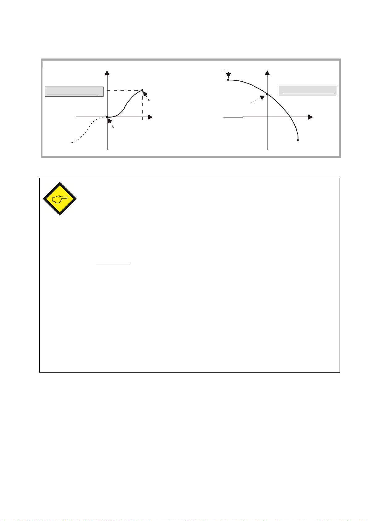
6.2.11. Hints for using the linearization function
x
y
LinearisationMode = 2
The subsequent drawing explains the difference between the modes of linearization.
y
Linearisation Mode = 1
*)
*) mirror of positive range
x-registers are to set the numeric value that the unit would display without
linearization
y-registers are to set the numeric value that should be displayed instead,
i.e. the (y3) setting will replace the (x3) display value
between the interpolation points the unit automatically uses linear
interpolation
(x0)= 0
(y0)= 0
(x15)= 1000
(y15)= 800
x
(x0)= -1000
(y0)= 900
(x8)= 0
(y8)= 750
(x15)= +1000
(y15)= - 600
x- registers have to use continuously increasing values, e.g. the lowest display
value must be set to register x0, and the highest display value must be set to
x16
Independent of the selected linearization mode, the possible setting range of
all registers x0, y0, … x16, y16 is always -199999 … 999999.
For measuring values outside of the defined linearization range, please note:
If the measuring value is lower than (x0), the linearization result will always
be (y0).
If the measuring value is higher than (x15), the linearization result will always
be (y15).
SD34002g_e.doc / Sep-13 Page 42 / 60
Page 43

6.2.12. Hints for models SD/SA/SR x3x (Display 8 decades)
No..
Menu
Name
----------------------------------------
Code
Min
Max
Default
0
F01
Preselection 1
00-19 999 999
99 999 999
1000
1
F01
Preselecti
on 2
01-19 999 999
99 999 999
2000
2
F01
Preselection 3
02-19 999 999
99 999 999
3000
3
F01
Preselection 4
03-19 999 999
99 999 999
4000
11
F02
Offset
A7-19 999 999
99 999 999
027F03
Set Value 1
C6-19 999 999
99 999 999
037F04
Set Value 2
D8-19 999 999
99 999 999
085F09
Analogue Start
J7-19 999 999
99 999 999
086F09
Analogue End
J8-19 999 999
99 999 999
10000
101
F12
P1(x)
L1-19 999 999
99 999 999
0
102
P1(y)
L2-19 999 999
99 999 999
0
.
131
P16(x)
O1-19 999 999
99 999 999
0
132
P16(y)
O2-19 999 999
99 999 999
0
133
F13
P1(x)
O3-19 999 999
99 999 999
0
134
P1(y)
O4-19 999 999
99 999 999
0
.
163
P16(x)
R3-19 999 999
99 999 999
0
164P16(y)R4-
19 999 999
99 999 999
0
Compared with a bigger display range models with 8 decade-displays provides a bigger range
for some specific parameters. The following table shows the parameters with the changed
parameter range.
---------
.
.
.
.
etc. etc. -19 999 999 99 999 999 0
etc. etc. -19 999 999 99 999 999 0
SD34002g_e.doc / Sep-13 Page 43 / 60
Page 44

7. Practical Examples for Setup and Scaling
For proper scaling of the unit is mandatory to respond to the following questions:
Which input frequency (Hz) will the encoders produce at a typical speed?
Which numeric value do we intend to display at this typical speed?
(sequence of numbers including the decimal positions)
Is the display characteristics proportional (speed) or reciprocal (time)?
The subsequent settings refer to the illustrations shown in chapter 4.
7.1. Settings for the Example a) of Chapter 4.1 (Speed Display)
Machine specifications: Calculations: Relevant parameters:
Encoder:
TTL A, /A, B, /B
4096 ppr.
Measuring wheel:
Circumference = 500
mm
(diameter = 159,2 mm)
Expected Line speed:
0 ... 300 meters/min
Desired display value:
0 ... 300,0 m/min
(one decimal position)
With a speed of 300 m/min
the measuring wheel will
rotate at 600 rpm.
With a 4096 ppr encoder
we will get 600 x 4096 =
2 457 600 Imp./ min equal
to 40 960 Imp /sec. (Hz)
This means at maximum
speed of 300 m/min the
encoder frequency is
40 960 Hz.
We expect a display value
of 3000 (to display 300.0)
F02.004 0
F02.0005 1
F03.022 0
F03.024 0,100 (assumed)
i.e. display cycle = 0.1 sec.
F03.025 0,10 (display zero with f < 10 Hz)
F03.027 40960
F03.028 3000
(= 300.0 with a decimal point)
F03.029 0
7.2. Settings for the Example b) of Chapter 4.1 (Baking Time)
Machine specifications: Calculations: Relevant parameters:
Proximity switch:
Standard PNP 3-wire
type
Sensed pinion:
16 teeth
70 rev. of the pinion =
1 meter of travelling
distance
Furnace length: 60 m
Range of baking times:
from 10 min. up to 2 h
Desired display format:
01h : 59min : 59sec
To run over the full furnace
distance of 60 meters, the
proximity will generate a
total number of impulses of
60 x 70 x 16 imp.
= 67200 impulses totally
With maximum speed we
expect a transition time of
10 min. equal to 600 sec.
With 67200 impulses in
600 seconds our frequency
corresponds to 112 Hz
F02.004 0
F02.005 0 (with clock display format
decimal points appear
automatically)
F03.022 5
F03.024 1,000 (assumed)
i.e. display cycle = 1 sec
F03.025 1,00
(frequencies < 1 Hz = standstill)
F03.027 112
F03.028 600
F03.029 Use setting "1" first and verify
correct display of seconds. Then
change over to "3" (clock format)
SD34002g_e.doc / Sep-13 Page 44 / 60
Page 45

7.3. Settings for Example "Differential Speed" of Chapter 4.4
Machine specifications: Calculations: Relevant parameters:
Both encoders:
1024 ppr quadrature
A / B / HTL 24 V
Circumferences (rolls):
all rolls should have the
same circumference of
350 mm
Speeds:
Maximum speed on
both conveyors is
200 m/min
Desired display:
Differential speed with
two decimal positions
(format +/-99.99 m/min)
Wit a maximum speed of
200 m/min and a roll
circumference of 0.350 m
we will get a roll rpm of
200 m/min : 0,350 m
= 571.43 rpm
This results in encoder
frequencies of
571.43 x 1024 Imp/min
= 585 143 Imp./min
= 9752.4 Imp./sec. (Hz)
F02.004 3
F02.005
F02.006
F02.007
F02.008
F02.009
F02.016 1
F03.022
F04.034
F03.023
F04.035
F03.024
F04.036
F03.025
F04.037
F03.027
F04.039
F03.028
F04.040
F03.029
F04.041
all = 2
both = 1000
(no re-scaling necessary)
It is advisable to synchronize
both measuring channels
whenever we use combined
display results
both = 1
For correct calculation of the
difference we must ensure that
both speeds have the same
direction (both positive or both
negative), i.e. either
[+Geber1] - [+Geber2] or
[-Geber1] - [-Geber2]
both = 0.500 (assumed), i.e.
display cycle = 0,5 sec.
both = 0,20 (assumed), i.e.
speed = 0 with f < 5 Hz
both = 9752 *)
both = 20 000 *)
(will appear as 200.00 since we
desire to have two decimal
positions)
both = 0
*) With high accuracy demand we are free to increase the frequency setting tenfold. This will allow to
also consider the remaining decimal position of our calculation (i.e. F03.027 = 97524).
In order to maintain the proportionality we have then to increase also the desired display value by
factor 10 (i.e. F03.028 = 200 000).
SD34002g_e.doc / Sep-13 Page 45 / 60
Page 46
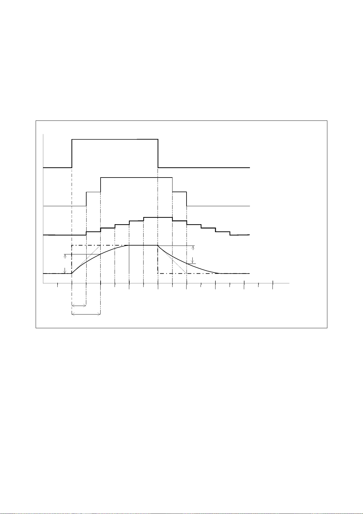
7.4. Example for Use of the Filter
The subsequent illustrations explain the mode of action of the Filter with different settings. For
140
160
msec.
Hz
SamplingTime = 10 msec
Time constant = 20 msec.(with filter setting = 5)
b)
With Filter set to "1" the unit forms a floating average value over the last two measuring
c)
With Filter set to "3" the unit forms a floating average value over the last eight measuring
d)
With Filter set to "5" the unit uses an exponential curve to smoothen the jump. Sin
ce the
this explanation we assume:
Sampling-Time = 10 msec
The input frequency jumps temporary up to a higher value, and after a time of 60 msec it
jumps back to the original value again
We use in sequence the filter settings 0, 1, 3 and 5
a) Jump of input frequency
b) Filter = 1
c) Filter =3
100%
63%
63%
d) Filter = 5
20
40
60 80 100 120
T
a) Jump: this shows how the unit would respond with the filter switched off
cycles. As a result, after the first sampling period we can only see 50% of the jump and
only one cycle later we can see 100%.
cycles. As a result, after the first sampling period we can only see 12.5% (1/8) of the jump
and only 7 cycles later we would come up to 100%. However, since the whole jump
duration is only 6 cycles long, the display already starts to step back to the previous value
before we reached the full jumping level
Time Constant of the exponential filter always equals 2 sampling times, we reach 63% of
the jumping level after 20 msec.
SD34002g_e.doc / Sep-13 Page 46 / 60
Page 47
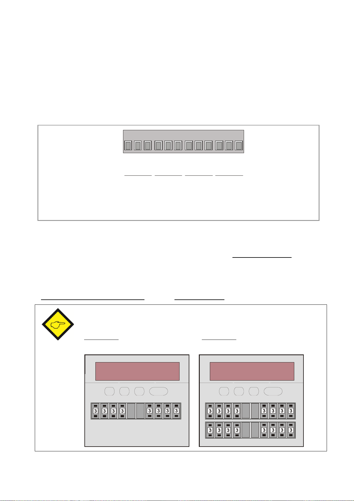
8. Appendix for models SD/SA/SR 6xx
Thumbwheel set 2
Thumbwheel set 4
8.1. Relay Outputs
All available models are shown in section 1. While models SD 3xx provide high-speed
transistor outputs only, all models SD 6xx provide four additional relay outputs, operating in
parallel to the high-speed transistor outputs K1 – K4.
All electrical connections of 6xx models are fully similar to the 3xx models, except that with 6xx
models the back plane is equipped with an additional 12-position terminal strip.
2 31 5 64 8 97 11 1210
X3
K4-C
K4-NO
K4-NC
K3-C
K3-NO
K3-NC
K2-C
K2-NO
K2-NC
K1-C
K1-NO
K1-NC
REL.4 REL.3 REL.2 REL.1
C =
NO =
NC =
Common contact
Normally open
Normally closed
8.2. Front Thumbwheel Switches
Moreover, the models shown below provide thumbwheel switches on the front panel, for
simple and easy setting of preselection levels. Every row allows in maximum 9 decades and
one blank field for separation. The customer is free to specify any desired combination and
number of decades individually, which is not wider than totally 10 spaces.
As an example, with model 642 it is possible to specify
“Set1 = 3 decades, Set2 = 6 decades”, or e.g. “Set1 = 8 decades” etc.
Where your order does not clearly state a different array of the thumbwheels, the
units will be supplied with 2 x 4 decades respectively 4 x 4 decades
Models 642 can have Models 644 can have
max. 2 switch sets on front max. 4 switch sets on front
Thumbwheel set 1 Thumbwheel set 2 Thumbwheel set 1
Thumbwheel set 3
SD34002g_e.doc / Sep-13 Page 47 / 60
Page 48

8.3. Specific Parameters for Units with Thumbwheel Switches
Setting of F06.071
00010203040506070809101112131415Sign of Thumbwheel 1
+-+-+-+-+-+-+-+-Sign of Thumbwheel 2
++--++--++--++--Sign of Thumbwheel 3
++++----++++----Sign of Thumbwheel 4
++++++++-------
-
The following parameter settings apply for units with thumbwheel switches only and are not
relevant for all other models:
8.3.1. Read and update thumbwheel switch settings All actual thumbwheel settings are automatically considered when the unit is powered up.
However, changes during normal operation will not be considered, unless upon special remote
command. This can either be the actuation of one of the front keys, or a command signal to one
of the control inputs.
Please see section 6.2.4 with the parameter group F05.
It is a “must” to assign the function "16" to at least one of the front keys or one of the
control inputs. These functions will read the settings of the front switches. Otherwise there
will be no way to activate changes of the switch settings during operation.
8.3.2. Positive or negative sign of thumbwheel settings In general and as a default, the front thumbwheel settings are assumed to have a positive sign.
Some applications may however require that one or the other setting should be interpreted as a
negative value.
Parameter F06.071 allows assigning negative signs to any of the front thumbwheels, following
a binary schema as shown in the table below:
8.3.3. Assignments between thumbwheels and switching outputs In general and as a default, thumbwheel switch set No.1 refers to output K1; thumbwheel
switch set No.2 refers to output K2 etc. This may be convenient for most of the applications,
but also cause inconvenience with some operating modes of the counter.
As an example, when using the “Sum Mode” (see section 4.3), the outputs K1 and K2 are firmly
attached to the encoder1 counter and outputs K3 and K4 are firmly attached to the sum of
encoder1 and encoder2.
SD34002g_e.doc / Sep-13 Page 48 / 60
Page 49

From this follows that, if you use a counter model with two sets of thumbwheels only
Setting of parameter F06.072
000102030405060708091011Thumbwheel set 1 is linked to output
K1K1K1K1K1K1K2K2K2K2K2K2Thumbwheel set 2 is linked to output
K2K2K3K3K4K4K1K1K3K3K4K4
Thumbwheel set 3 is linked to output
K3K4K4K2K2K3K3K4K4K1K1K3Thumbwheel set 4 is linked to output
K4K3K2K4K3K2K4K3K1K4K3K1Setting of parameter F06.072
121314151617181920212223Thumbwheel set 1 is linked to outpu
tK3K3K3K3K3K3K4K4K4K4K4K4
Thumbwheel set 2 is linked to output
K1K1K2K2K4K4K1K1K2K2K3K3Thumbwheel set 3 is linked to output
K2K4K4K1K1K2K2K3K3K1K1K2Thumbwheel set 4 is linked to output
K4K2K1K4K2K1K3K2K1K3K2
K1
(thumbwheel set 1 and thumbwheel set 2), you would only have preselections referring to
encoder1, but no thumbwheel access to the sum.
To avoid such kind of limitations, parameter F06.072 allows free assignments between any of
the thumbwheel switch sets (switch1 to switch4, see previous figure) and any of the four
outputs (K1 to K4)
SD34002g_e.doc / Sep-13 Page 49 / 60
Page 50

9. Appendix: Serial Communication Details
Serial communication with the counter can be used for the following purposes:
PC setup of the counter, using the OS32 Operator software
Automatic and cyclic transmission of counter data to remote devices like PC, PLC or
Data Logger
Communication via PC or PLC, using the communication protocol
This section describes the essential and basic communication features only. Full details are
available from the special SERPRO manual.
9.1. Setup of the Counter by PC
Connect the counter to your PC as shown in section 3.6 of this manual. Start the OS32 Operator
software. After a short initializing time you will see the following screen:
If your screen remains empty and the headline of your PC says „OFFLINE“, select „Comms“ of
the menu bar and check your serial communication settings.
The edit field on the left shows all actual parameters and provides full editing function. The
„File“ menu allows to store complete sets of parameters for printout or for download to a
counter.
When editing parameters, please use the ENTER key of your PC after each entry, to ensure
storage of your data to the counter.
SD34002g_e.doc / Sep-13 Page 50 / 60
Page 51

9.2. Automatic and Cyclic Data Transmission
F10.111
= 6 :
Actual speed of encoder 1
= 7 :
Actual speed
of encoder 2
= 8 :
Actual analogue output voltage (SA models only)
= 9 :
Latest minimum value (minimum record memory)
= 10 :
Latest maximum value (maximum record memory)
= 14 :
Actual value indicated in the display
(Unit No.)
F10.109 = 0 :
11+/-XXXXXXLF
CR
F10.109 = 1 :
+/-XXXXXXLF
CR
EOT
AD1
AD2
C1C2ENQ
EOT = Control ch
aracter (Hex 04)
ASCII
-
Code:
EOT11:6
ENQ
Hexadecimal:
0431313A3905Binary:
0000 0100
0011 0001
0011 0001
0011 1010
0011 1001
0000 0101
Set any cycle time unequal to zero to parameter F10.110.
Set the serial access code of the register you would like to transmit to parameter F10.111. In
theory you could transmit any of the internal registers by serial link, however only the following
registers make really sense:
Dependent on the setting of parameter F10.109 the unit transmits one of the following data
strings, under cycle control of the timer:
(xxxx = counter data*, LF = Line Feed <hex. 0A>, CR = Carriage Return <hex 0D>)
*) Leading zeros will not be transmitted
9.3. Communication Protocol
When communicating with the unit via protocol, you have full read/write access to all internal
parameters, states and actual counter values. The protocol uses the DRIVECOM standard
according to DIN ISO 1745. A list with the most frequently used serial access codes can be
found in the previous section.
To request data from the counter, the following request string must be sent:
AD1 = Unit address, High Byte
AD2 = Unit address, Low Byte
C1 = Register code to read, High Byte
C2 = Register code to read, Low Byte
ENQ = Control character (Hex 05)
The example shows how to request for transmission of the actual encoder 1 speed
(register code :9), from a unit with unit address 11:
SD34002g_e.doc / Sep-13 Page 51 / 60
Page 52

Upon correct request, the counter will respond:
STXC1C2x x x x x x x
ETX
BCC
STX = Control character (Hex 02)
EOT
AD1
AD2
STXC1C2
x x x x x x x
ETX
BCC
EOT = Control
character (Hex 04)
C1 = Register code to read, High Byte
C2 = Register code to read, Low Byte
xxxxx = Counter data *)
ETX = Control character (Hex 03)
BCC = Block check character
*) Leading zeros will not be transmitted
The Block-Check-Character represents the EXCLUSIVE-OR function of all characters from
C1 to ETX (both comprised).
To write to a parameter, you have to send the following string:
AD1 = Unit address, High Byte
AD2 = Unit address, Low Byte
STX = Control character (Hex 02)
C1 = Register code to write, High Byte
C2 = Register code to write, Low Byte
xxxxx = Value of the parameter
ETX = Control character (Hex 03)
BCC = Block check character
Upon correct receipt the unit will respond by ACK, otherwise by NAK.
Every new parameter sent will first go to a buffer memory, without affecting the actual
measuring process. This function enables the user, during normal measuring operation, to
prepare a complete new parameter set in the background.
To activate transmitted parameters, you must write the numeric value “1” to the “
Activate Data“ register. This immediately activates all changed settings at the same time.
Where you like the new parameters to remain valid also after the next power up of the unit,
you still have to write the numeric value “1” to the „Store EEProm“ register. This will store all
new data to the EEProm of the unit. Otherwise, after power down the unit would return with
the previous parameter set.
SD34002g_e.doc / Sep-13 Page 52 / 60
Page 53

9.4. Serial Register Codes
Function
Code
Activate Data
67
Store EEProm
68
Serial command
Code
Read thumbwheel switches (see F05.050 = 16) *)
59
Hardware keypad disable (see F05.050 = 15) *)
60
Clear min/max record memory (see F05.050
= 14) *)
61
Cycle the display (see F05.050 = 13) *)
62
Remote start
-
up delay (see F05.050 = 12) *)
63
Release latch / maintain of outputs and relays (see F10.114) *)
64
Freeze encoder frequencies (see F10.113) *)
65
Substitute en
coder frequencies (see F10.112) *)
66
Activate Data (activation of serial transmit parameters) **)
67
Store EEProm (storage of parameters in EEProm) **)
68
ASCII
EOT11
STX601ETX
BCC
Hex
0 4
3 1
3 1
0 2
3 6
3 0
3 1
0 3
3 4
ASCII
EOT11
STX600ETX
BCC
Hex
0 4
3 1
3 1
0 2
3 6
3 0
3 0
0 335
9.4.1. Communication Commands
These commands have to be sent to the unit every time after one or several new parameters
have been transmitted, in order to activate or to store the new values. Both commands are
"dynamic", i.e. it is sufficient to just send the data value "1" to the corresponding code position.
Example: send the command "Activate Date" to the unit with Unit No. 11:
ASCII EOT 1 1 STX 6 7 1 ETX BCC
Hex 0 4 3 1 3 1 0 2 3 6 3 7 3 1 0 3 3 3
9.4.2. Control Commands
*) Sending data value "1" to the corresponding location will switch the command
persistently ON until sending again the data "0" to the same location
**) Sending data value "1" to the corresponding location will switch the command
ON and the bit will automatically reset to 0 after execution
Example: Switch on the hardware keypad lock (disable keypad of unit No. 11):
Switch off the hardware keypad lock (enable keypad of unit No. 11 again)
SD34002g_e.doc / Sep-13 Page 53 / 60
Page 54

9.4.3. Code list of all parameters
No..
Menu
Name
-------------------------------------------------
Code
Min
Max
Default
0
F01
Preselection 1
00-199999
999999
1000
1
Preselection 2
01-199999
999999
2000
2
Preselection 3
02-199999
999999
3000
3Preselection 4
03-199999
999999
4000
4
F02
Operational Mode
A00815
Decimal Point 1
A10506
Decimal Point 2
A20507
Decimal Point 12
A30508
Display Value
A41999999
1000
9
New Display Value
A51999999
1000
10
Display Mode
A603
0
11
Offset
A7-199999
999999
012Brightness
A804013
Display Update
A90100014
Sampling Pulses
B0030000
015Wait Time Sampling
B109999
5016Synchronization
B201017
Input Limitation
B303018
Percent Format
B403019
F03
Encoder Properties 1
B805120
Direction 1
B901021
Sampling Time 1
C009999
122Wait Time 1
C119999
10023Filter 1
C208024
Input Value 1
C31999999
1000
25
Display Value 1
C41999999
1000
26
Display Mode 1
C503027Set Value 1
C6-199999
999999
028Start
-
up Mode 1
C7010
0
29
Standstill Time 1
C809999
0
SD34002g_e.doc / Sep-13 Page 54 / 60
Page 55

SD34002g_e.doc / Sep-13 Page 55 / 60
No..
Menu
Name
-------------------------------------------------
Code
Min
Max
Default
30
F04
Encoder Properties 2
D005131
Direction 2
D101032
Sampling Time 2
D209999
133Wait Time 2
D319999
10034Filter 2
D408039
Input Value 2
D51999999
1000
35
Display Value 2
D61999999
1000
36
Display Mode 2
D703037
Set Value 2
D8-199999
999999
038Start
-
up Mode 2
D9010039Standstill Time 2
E009999
040F05
Key Up Function
E2017041
Key Down Function
E3017042
Key Enter Function
E4017043
Input 1 Configuration
E507044
Input 1 Function
E6017045
Input 2 Configuration
E707046
Input 2 Funct
ionE80170
47
Input 3 Configuration
E907
0
48
Input 3 Function
F0017049
Input 4 Configuration
F103050
Input 4 Function
F2017051
F06
Pulse Time 1
F40999052
Pulse Time 2
F50999053
Pulse Time 3
F60999054
Pulse Time
4F70
999055
Hysteresis 1
F8099999
056Hysteresis 2
F9099999
057Hysteresis 3
G0099999
058Hysteresis 4
G1099999
059Preselection Mode 1
G208060
Preselection Mode 2
G308061
Preselection Mode 3
G408062
Preselection
Mode 4
G508063
Output Polarity
G6015064
Thumbwheel Sign
G7015065
Thumbwheel Configuration
G8023066
Output Lock
G901067
Start up Relay
H0015068
Lock Relay
H1031
0
Page 56

SD34002g_e.doc / Sep-13 Page 56 / 60
No..
Menu
Name
------------------------------------
-------------
Code
Min
Max
Default
69
F07
Protect F01
H40999999
070Protect F02
H50999999
071Protect F03
H60999999
072Protect F04
H70999999
073Protect F05
H80999999
074Protect F06
H90999999
075Protect F07
I00999999
607876
Protect F08
I10999999
6078
77
Protect F09
I20999999
078Protect F10
I30999999
079Protect F11
I40999999
6078
80
Protect F12
I50999999
081Protect F13
I60999999
082F08
Trigger Threshold 1
J130250
16683Trigger Thresh
old 2
J230250
16684F09
Analogue Format
J603085
Analogue Start
J7-199999
999999
086Analogue End
J8-199999
999999
10000
87
Analogue Swing
J911000
100
88
Analogue Offset
K0-10000
10000
089Analogue Assignment
K105090
F10
Unit N
umber
900991191
Serial Baud Rate
9106092
Serial Format
9209093
Serial Protocol
K201194
Serial Timer (s)
K3099999
095Register Code
K40261496
Command Set
K503097
Command Freeze
K603098
Command Selfhold
K7015
0
Page 57

No..
Menu
Name
-------------------------------------------------
Code
Min
Max
Default
99
F11
Linearisation Mode 1
K9020100
Linearisation Mode 2
L0020101
F12
P1(x)
L1-199999
999999
0
102
P1(y)
L2
etc. etc.
131
P16(x)
O1
132
P16(y)
O2
133
F13
P1(x)
O3-199999
999999
0
134
P1(y)
O4
163
P16(x)
R3
164
P16(y)
R4
No.
Name
----------------
Code
Cmd Bit
1
Load Presel.
59
0100
2
Keyboard L
ock600080
3
Reset Min./Max.
61
0040
4
Display Switch
62
0020
5
Startup Inhibit
63
0010
6
Selfhold Release
64
0008
7
Freeze Frequency
65
0004
8
Set Frequency
66
0002
9
Activate Data
67
1000
10
Store EEProm
68
0001
No.
Name
-----------
Cmd
Bit0Unit ready
0001
1
Output 1
0004
2
Output 2
0008
3
Output 3
0010
4
Output 4
0020
5
Status A/B 2
0040
6
Status A/B 1
0080
Name
Serial Code
High Byte
Low Byte
Actual speed of encoder 1
:9Actual speed of encoder
2;0
Actual analogue output voltage (SA models only)
:8Latest minimum value (minimum record memory)
<
0
Latest maximum value (maximum record memory)
<
1
Actual value indicated in the display
;
4
etc. etc.
9.4.4. Code list of commands 9.4.5. Code list of outputs
9.4.6. Code list of variables
SD34002g_e.doc / Sep-13 Page 57 / 60
Page 58

10. Specifications
AC power supply
:
24 V
+/-10%,
15 VA
DC power supply
:
Aux. encoder supply outputs:
2 x 5,2 VDC, 150 mA each
Inputs
:
2 universal encoder inputs
Max. frequency (per encoder)
:
RS422 and TTL differential:
1 MHz
Switching outp
uts (all models)
:
4 fast power transistors 5
-
30V, 350 mA
Serial link
:
SD / SA:
RS232,
2400
–
38400 Bauds
Analogue outputs
:
0/4...20mA (load max.270 Ohm)
Ambient temperature
:
Operation: 0
-
45°C ( 32
–
113°F)
Housing
:
Norly UL94
–V-0Display
:
Protection class (front side only)
:
All models without front thumbwheels:
IP65
Screw terminals
:
Conformity and standards:
EM
C 2004/108/EC:
EN 61000
-6-
2
~
24V- (17 – 40V), approx. 100 mA (+ encoders)
2 x 24V DC, 120 mA each
(Ri = 8.5 kΩ each channel)
4 digital control inputs HTL (Ri = 3.3 kΩ)
Low < 2.5 V, High > 10 V, min. pulse width 50 µsec.
HTL single ended: 200 kHz
TTL single-ended: 200 kHz
(b)
Response time < 1 msec. (a),
Relay outputs :
(models SD/SA/SR 6xx only)
(models SA only)
Protection class rear side :
4 relays (dry changeover contacts) (b)
AC switching capability max. 250 V/ 1 A/ 250 VA
DC switching capability max. 100 V/ 1A/ 100 W
SR: RS232 and RS485, 2400 – 38400 Bauds
0…+/- 10V (load max. 2 mA)
Resolution 14 bits, Accuracy 0.1%
Response time < 1 msec. (a)
Storage: -25 - +70°C (-13 – 158°F)
6 Digit, LED, high- efficiency red, 15 mm (0.59'')
All models with front thumbwheels: IP20
(with plexi-glass cover part # 64026 also IP54)
IP20
(a) Continuous serial communication may temporary increase response times
Overall response = measuring time + response time
(b) Diode or RC filtering is mandatory when switching inductive loads
SD34002g_e.doc / Sep-13 Page 58 / 60
Cross section max. 1.5 mm²,
EN 61000-6-3
LV 2006/95/EC: EN 61010-1
Page 59

11. Dimensions
110,0 (4.331’’)
4
4
,0(
1.7
3
2
)
48,0(1.890)
Models 340:
96,0 (3.780’’)
9,0 (.345)
8,0
129,0 (5.079)
140,5 (5.531)
91,0 (3.583)
(.315)
10,0
(.394)
Panel cut out: 91 x 44 mm (3.583 x 1.732’’)
SD34002g_e.doc / Sep-13 Page 59 / 60
Page 60
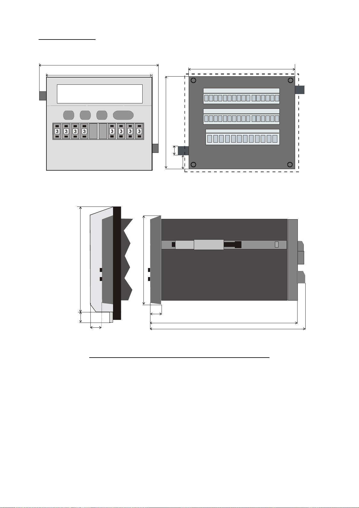
Models 640 to 644:
110,0 (4.331’’)
9
0
,5(3.56
3
)
88,5 (3.484)
96,0(3.78
)
With optional plexi glass cover
96,0 (3.780’’)
for protection class IP65
(mks part # 64026)
8,0 (.315)
10,0
(.394)
111,5 (4.39)
12,0 (.472)
18,5 (.728)
9,0 (.345)
129,0 (5.079)
140,5 (5.531)
Panel cut out (w x h): 89 x 91 mm (3.504’’ wide x 3.583’’ high)
SD34002g_e.doc / Sep-13 Page 60 / 60
 Loading...