

Page 1
ELEKTRO-TRADING sp. z o.o
Tel. +48 (0-32) 734-55-72
Tel/Fax +48 (0-32) 734-55-70
E-Mail et@elektro-trading.com.pl
http://www.elektro-trading.com.pl
control – motion – interface
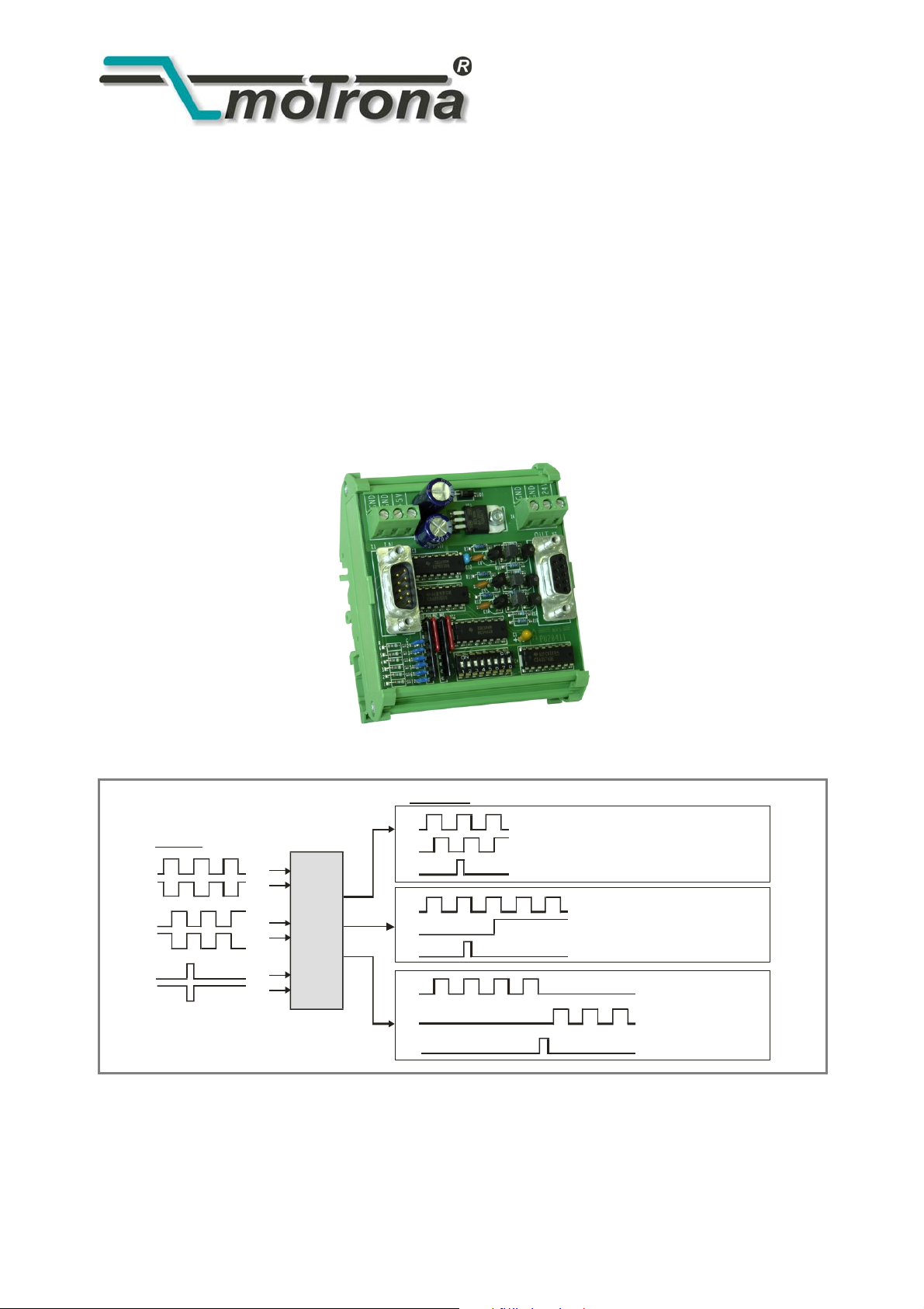
PU 204
Level Converter and Direction Signal Generator
Inputs:
RS422, 5V TT L
A
/A
B
/B
Z
/Z
PU
204
Outputs:H TL 10 - 30V
A
B
Z
A
Z
Impulses forward
Impulses reverse
Z
Quadrature
(2 x 90°)
Static dir ec t ion s i g nal
Se parate channels
forward/reverse
Operating Instructions
PU20402a_e.DOC / Feb-08 Page 1 / 8
Page 2

Safety Instructions
• This manual is an essential part of the unit and contains important hints about
function, correct handling and commissioning. Non-observance can result in
damage to the unit or the machine or even in injury to persons using the
equipment!
• The unit must only be installed, connected and activated by a qualified electrician
• It is a must to observe all general and also all country-specific and application-
specific safety standards
• When this unit is used with applications where failure or maloperation could cause
damage to a machine or hazard to the operating staff, it is indispensable to meet
effective precautions in order to avoid such consequences
• Regarding installation, wiring, environmental conditions, screening of cables and
earthing, you must follow the general standards of industrial automation industry
• - Errors and omissions excepted –
Version: Description:
PU20402a/hk/June 2007 First edition format A5
PU20402a_e.DOC / Feb-08 Page 2 / 8
Page 3

Table of Contents
1. Introduction..........................................................................................4
2. Construction, Dimensions .................................................................... 4
3. Power Supply ....................................................................................... 5
4. Setting of the Direction Signal ............................................................6
4.1. Indication of direction by phase displacement (quadrature pulses) .....................6
4.2. Indication of direction by static direction output ..................................................6
4.3. Separate channels for forward and reverse pulses ..............................................6
5. Connection of the Impulse Input..........................................................7
5.1. Where at the input you use a shaft encoder which needs to be supplied by the
PU204 unit: ............................................................................................................7
5.2. Where you use an encoder with separate supply, or the encoder simulation of a
drive:......................................................................................................................7
5.3. Where you like to use fully differential mode:......................................................7
6. Technical Specifications ...................................................................... 8
PU20402a_e.DOC / Feb-08 Page 3 / 8
Page 4

1. Introduction
PU204 is designed to convert impulse levels from a TTL or RS422 format to a 10-30 V HTL
format. At same time, the unit is suitable to convert the information of direction from the
quadrature format to other usual standards like shown on the title page.
For vice-versa conversion of level and direction signal, see type PU202.
2. Construction, Dimensions
The unit is designed as a PCB with a plastic frame for direct and easy DIN rail mounting.
The impulse inputs are available on a 9-pin Sub-D-connector (male).
The outputs are available on a 9-pin Sub-D-connector (female). For power supply of the unit and
of encoders, two 3-position screw terminals are available.
+5V
GND
GND
ON
123 45678
OFF
85 (3.346 ’’)
GND
204PU10
+24V
GND
90
(3.543’’)
38
(1.496’ ’)
50
(1.969’’ )
PU20402a_e.DOC / Feb-08 Page 4 / 8
Page 5

3. Power Supply
The unit needs a 10-30 VDC supply. The level of the supply voltage automatically determines
also the level of the output swing (24V supply will cause pulse output with 24V level also).
The supply voltage can either be applied to the screw terminals marked “GND” and “+24V”, or
also via the female Sub-D-9 output connector, using pin 5 (GND) and pin 4 (+24V).
For encoder supply, an auxiliary voltage of +5 V / 100 mA is available at pin 4 of the input
connector (Sub-D-9 male). This voltage can also be taken from the screw terminal marked
“+5V”.
For use of the +5V auxiliary voltage at the input connector or the screw terminal, you must set
positions 7 and 8 of the 8-position DIL switch to “ON”.
Warning!
Never, with DIL switch position 7 and 8 “ON“, any external voltage must be
applied to input connector pin 4 or to screw terminal marked “+5V”! This
would cause irrevocable damage to the unit!
GND
GND
GND
GND
+5V
Inp ut:
TTL/RS422
+5V
/A
B
/B
Z
/Z
GND
Screen
4
3A
2
1
9
7
6
8
5
7
VCC
+5V
Stab.
GND
+24V
Output HTL
4
3A
1B
7Z
5
Scre e n
(Sub- D- 9 female)(Sub- D- 9 male)
+24V IN
GND
PU20402a_e.DOC / Feb-08 Page 5 / 8
Page 6

C
C
C
4. Setting of the Direction Signal
The unit, at the output, can use three different modes to indicate the sense of rotation. Output
modes can be selected by the 8-position DIL switch on the print:
4.1. Indication of direction by phase displacement (quadrature pulses)
90°
A
B
A
B
forward
reverse
90°
1 2345678
DIL -Swit ch:1, 3, 5 O N
4.2. Indication of direction by static direction output
A
B
B Low = for ward B High = reverse
12345 678
DIL-Sw itch:2, 3, 5 ON
VC
GND
ON
OF F
2, 4, 6 OFF
VC
GND
ON
OFF
1, 4, 6 OFF
4.3. Separate channels for forward and reverse pulses
A
12345 678
B
Forw ard:
Pulses on A with
B = Low
Reverse:
Pulses on B with
A = Low
DIL-Sw itch:1, 4, 6 ON
VC
GND
ON
OFF
2, 3, 5 OFF
PU20402a_e.DOC / Feb-08 Page 6 / 8
Page 7

5. Connection of the Impulse Input
5.1. Where at the input you use a shaft encoder which needs to be
supplied by the PU204 unit:
• Set DIL-switches 7 + 8 to “ON”.
• Supply the encoder from pins 4 and 5.
• Connect the screen to the supply minus wire at the PU204 side (pin 5).
5.2. Where you use an encoder with separate supply, or the encoder
simulation of a drive:
• Set DIL-switch 7 to “OFF”, 8 to “ON”.
• Connect the screen to GND pin 5 on the PU204 side.
5.3. Where you like to use fully differential mode:
• Connect only the impulse lines.
• Set DIL-switch 7 to “OFF”, 8 to “ON”.
• Connect the screen to GND pin 5 on the PU204 side.
PU20402a_e.DOC / Feb-08 Page 7 / 8
Page 8

6. Technical Specifications
Power Supply : 10 - 30 V DC
Current consumption : 85 mA (with 24V input, without encoder supply)
Encoder Supply : + 5 V / 100 mA (switch selectable)
Max. frequency : 200 kHz
Input : RS422 or TTL A, /A, B, /B, Z, /Z
Output : HTL, push/pull, A, B, Z / 10 - 30V, 30 mA each line
Propagation delay : approx. 800 ns
Operating temperature : 0 – 45 °C (32 - 113 °F)
Dimensions : See drawing page 2
Weight : approx. 100g
Conformity and Standards : EMC 89/336/EEC: EN 61000-6-2
EN 61000-6-3
LV73/23/EEC: EN 61010-1
PU20402a_e.DOC / Feb-08 Page 8 / 8
 Loading...