

Page 1
Operating Manual
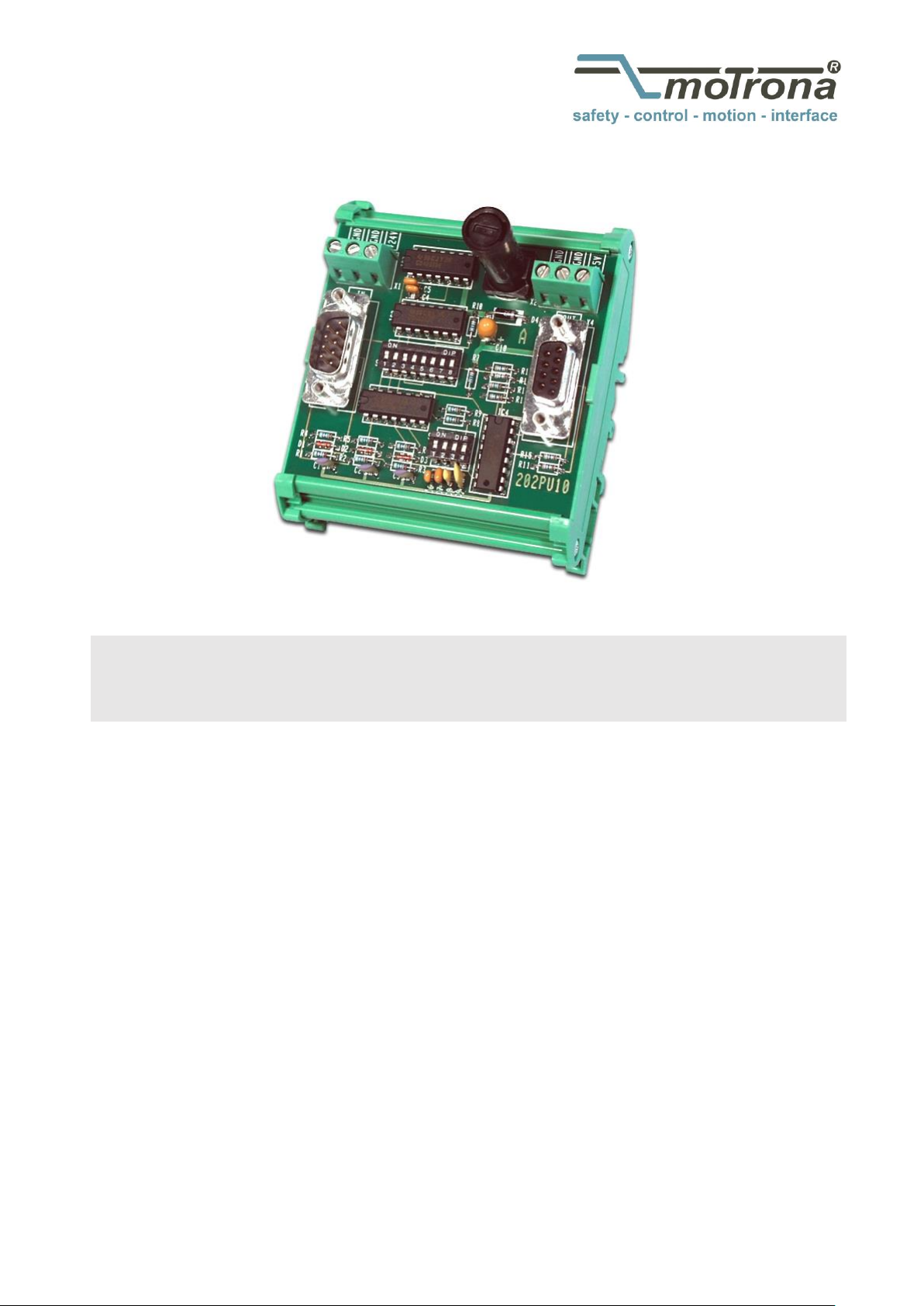
PU202
Level converter & encoder signal generator without potential separation
Product features:
Converts HTL signals from 10 up to 30 V (A / B / Z) into the corresponding
TTL / RS422 format (the inverted channels included)
Further different standards of direction signals can be converted into
a 90° phase shifted A/B square wave signal
Open PCB version with plastic-housing for a simple snapping onto
top hat rails according to EN 60715
Input frequency max. 200 kHz
5 VDC power supply
motrona GmbH, Zeppelinstraße 16, DE - 78244 Gottmadingen, Tel. +49 (0) 7731 9332-0, Fax +49 (0) 7731 9332-30, info@motrona.com, www.motrona.com
Page 2

Version:
Description:
PU20202c/Sept.07/hk
Remake as brochure with A5 format
Pu202_02d/Okt-15/ag
- Safety Instructions and Technical Specification updated
- Design updated and Legal notices supplemented
- Pulse diagram correction (10 … 30 V instead of 12-30V)
- Pulse diagram moved from page 1 into a new chapter (2.1)
Legal notices:
All contents included in this manual are protected by the terms of use and copyrights of motrona GmbH. Any reproduction,
modification, usage or publication in other electronic and printed media as well as in the internet requires prior written
authorization by motrona GmbH.
Table of Contents
1. Safety Instructions and Responsibility ......................................................... 3
1.1 General Safety Instructions ................................................................................... 3
1.2 Use according to the intended purpose ................................................................ 3
1.3 Installation ............................................................................................................. 4
1.4 Cleaning, Maintenance and Service Notes ........................................................... 4
2. Introduction ................................................................................................. 5
3. Construction, Dimensions ............................................................................ 6
4. Power Supply ............................................................................................... 7
5. Connections ................................................................................................. 7
6. Modes of Operation ..................................................................................... 8
6.1. Quadrature Input A/B ............................................................................................ 8
6.2. Impulses on line A only, static direction select on line B ..................................... 8
6.3. Separate impulse lines for forward and reverse ................................................... 8
7. Output Signal ............................................................................................... 9
8. Technical Specifications ............................................................................ 10
Pu202_02d_oi_e.doc / Apr-16 Page 2 / 10
Page 3

1. Safety Instructions and Responsibility
1.1 General Safety Instructions
This operation manual is a significant component of the unit and includes important rules and
hints about the installation, function and usage. Non-observance can result in damage and/or
impairment of the functions to the unit or the machine or even in injury to persons using the
equipment!
Please read the following instructions carefully before operating the device and observe all
safety and warning instructions! Keep the manual for later use.
A pertinent qualification of the respective staff is a fundamental requirement in order to use
these manual. The unit must be installed, connected and put into operation by a qualified
electrician.
Liability exclusion: The manufacturer is not liable for personal injury and/or damage to property
and for consequential damage, due to incorrect handling, installation and operation. Further
claims, due to errors in the operation manual as well as misinterpretations are excluded from
liability.
In addition the manufacturer reserve the right to modify the hardware, software or operation
manual at any time and without prior notice. Therefore, there might be minor differences
between the unit and the descriptions in operation manual.
The raiser respectively positioner is exclusively responsible for the safety of the system and
equipment where the unit will be integrated.
During installation or maintenance all general and also all country- and application-specific
safety rules and standards must be observed.
If the device is used in processes, where a failure or faulty operation could damage the system
or injure persons, appropriate precautions to avoid such consequences must be taken.
1.2 Use according to the intended purpose
The unit is intended exclusively for use in industrial machines, constructions and systems. Nonconforming usage does not correspond to the provisions and lies within the sole responsibility
of the user. The manufacturer is not liable for damages which has arisen through unsuitable
and improper use.
Please note that device may only be installed in proper form and used in a technically perfect
condition - in accordance to the Technical Specifications (see chapter 8). The device is not
suitable for operation in explosion-proof areas or areas which are excluded by the EN 61010-1
standard.
Pu202_02d_oi_e.doc / Apr-16 Page 3 / 10
Page 4

1.3 Installation
The device is only allowed to be installed and operated within the permissible temperature
range. Please ensure an adequate ventilation and avoid all direct contact between the device
and hot or aggressive gases and liquids.
Before installation or maintenance, the unit must be disconnected from all voltage-sources.
Further it must be ensured that no danger can arise by touching the disconnected voltagesources.
Devices which are supplied by AC-voltages, must be connected exclusively by switches,
respectively circuit-breakers with the low voltage network. The switch or circuit-breaker must
be placed as near as possible to the device and further indicated as separator.
Incoming as well as outgoing wires and wires for extra low voltages (ELV) must be separated
from dangerous electrical cables (SELV circuits) by using a double resp. increased isolation.
All selected wires and isolations must be conform to the provided voltage- and temperatureranges. Further all country- and application-specific standards, which are relevant for structure,
form and quality of the wires, must be ensured. Indications about the permissible wire crosssections for wiring are described in the Technical Specifications (see chapter 8).
Before first start-up it must be ensured that all connections and wires are firmly seated and
secured in the screw terminals. All (inclusively unused) terminals must be fastened by turning
the relevant screws clockwise up to the stop.
Overvoltages at the connections must be limited to values in accordance to the overvoltage
category II.
For placement, wiring, environmental conditions as well as shielding and earthing/grounding of
the supply lines the general standards of industrial automation industry and the specific shielding
instructions of the manufacturer are valid. Please find all respective hints and rules on
www.motrona.com/download.html --> “[General EMC Rules for Wiring, Screening and Earthing]”.
1.4 Cleaning, Maintenance and Service Notes
To clean the front of the unit please use only a slightly damp (not wet!), soft cloth. For the rear
no cleaning is necessary. For an unscheduled, individual cleaning of the rear the maintenance
staff or assembler is self-responsible.
During normal operation no maintenance is necessary. In case of unexpected problems, failures
or malfunctions the device must be shipped for back to the manufacturer for checking,
adjustment and reparation (if necessary). Unauthorized opening and repairing can have
negative effects or failures to the protection-measures of the unit.
Pu202_02d_oi_e.doc / Apr-16 Page 4 / 10
Page 5

2. Introduction
PU202 is designed for conversion of HTL impulse signals (10 … 30 VDC) to RS422 Standard or
TTL level, including complements. Also, the unit can translate different modes of direction
control to the A / B quadrature mode (2 x 90°), which is required for the majority of controllers.
Some measuring systems or PLC positioning cards generate pulses on one line whilst another
line provides static information of the direction of rotation. Other systems use two separate
lines, one to transmit the forward pulses and the other to transmit the reserves pulses.
The PU 202 converter can translate any of these formats to the usual A/B quadrature standard,
as shown in the drawing below.
2.1. In- and output pulse diagram:
For vice-versa conversion of level and direction signal, see type PU204.
Pu202_02d_oi_e.doc / Apr-16 Page 5 / 10
Page 6

3. Construction and dimensions
The unit is designed as a PCB with a plastic-housing for a simple snapping onto top hat rails
according to the EN 60715 norm.
The impulse input are available on a 9-pin SUB-D-connector (female).
For power supply of the unit and of encoders, two 3-way screw terminals are available.
Pu202_02d_oi_e.doc / Apr-16 Page 6 / 10
Page 7

4. Power Supply
GND
GND
+24V )
*
GND
GND
+5V
4
+24V*)
3IN A
1IN B
7IN Z
5
GND
1
9
7
6
5
GND
2
3 A
4
+5V
/A
B
/B
Z
/Z
Fuse
0,315mt
+5V
GND
(Sub - D- 9 male) (Su b- D- 9 female)
Screen Screen
Power Supply
The unit does not possess its own power supply unit. It must be supplied by an external source
with +5 VDC +/-10% (approx. 50mA), which can either be connected to the 9-position output
connector or the screw terminals marked “GND” and “5V” (see connection diagram below).
Pin 4 of the output connector is internally connected to the +5V screw terminal.
Also, Pin 4 of the input connector is on same potential as the +24V screw terminal.
This enables the user to externally supply an encoder system via the Sub- D- connector without
necessity to split the 9- wire cable.
The +24V*) screw terminal serves as encoder supply only and does not affect the operation of
the unit.
The 5 VDC unit supply is protected against wrong polarity by a diode and a fuse.
5. Connection diagram
Pu202_02d_oi_e.doc / Apr-16 Page 7 / 10
Page 8

6. Operation Modes
= ON
1 2 3 4 5 6 7 8
ON
OFF
S2
Low=forward
High = reverse
1 2 3 4 5 6 7 8
ON
OFF
S2
1 2 3 4 5 6 7 8
ON
OFF
S2
line forward
line reverse
The output signals are always the same, independent of the mode of operation, but the inputs
may have different functions. The mode can be selected by the 8-position DIL-switch S2. The
index pulse (Z) will only be converted to TTL-level, but not be affected by the mode setting.
6.1. Quadrature Input A/B (2 x 90°)
6.2. Impulses on line A only, static direction select on line B
6.3. Separate impulse lines for forward and reverse
This mode of operation requires that one of the two inputs is in LOW state while the other
input line receives the pulses.
Pu202_02d_oi_e.doc / Apr-16 Page 8 / 10
Page 9

7. Output Signal
1 2 3 4
ON
OFF
S1
0,4 µsec. (625kHz)
1 2 3 4
ON
OFF
S1
1,1 µsec. (227kHz)
1 2 3 4
ON
OFF
S1
4 µsec. (62,5kHz)
1 2 3 4
ON
OFF
S1
11 µsec. (22,7kHz)
1 2 3 4
ON
OFF
S1
40 µsec. (6,25kHz)
The quadrature output operates with a phase displacement between signals A/A’ and B/B’.
In case of a quadrature type input signal with 90° phase shifting according to 6.1, the output
appears with the same displacement of 90°. However, with inputs according to 6.2 and 6.3, the
phase displacement at the output will be constant in time, therefore will correspond to 90° only
at a certain input frequency and will become smaller with lower input frequencies.
This in general, this is not a restriction for proper detection of the direction, because most of
the controllers can clearly interpret this information, even when the phase is barely visible on
an oscilloscope.
DIL switch slider S1 permits selection of 5 different times. The frequency is shown in brackets
at which the phase displacement corresponds to 90°.
Pu202_02d_oi_e.doc / Apr-16 Page 9 / 10
Page 10

8. Technical Specifications
Power supply:
Input voltage:
Protection:
Ripple:
Consumption:
Connections:
5 VDC +/- 10 %
reverse polarity protection and fuse (0, 315 A medium time lag)
≤ 10 %
approx. 50 mA (unloaded)
selectively by 1,5 mm² / AWG 16 screw terminal
or 9-pin male SUB-D connector
Encoder supply:
Only external voltage:
The external supplied voltage is looped-trough and available
at the male SUB-D connector (no fragmentation necessary).
Incremental input:
Levels:
Input logic:
Internal resistance:
Channels:
Frequency:
Connections:
HTL (10 … 30 V)
PNP
Ri ≈ 10 kOhm
A, B, Z
max. 200 kHz
male SUB-D connector, 9-pin
Incremental output:
Levels:
Channels:
Output current:
Signal delay:
Connections:
5 V-TTL / RS422
A, /A, B, /B, Z, /Z
max. 20 mA per channel
approx. 800 ns
female SUB-D connector, 9-pin
Housing:
Material:
Mounting:
Dimensions (w x h x d):
Protection class:
Weight:
plastic
35 mm top hat rail (according to EN 60715)
78 x 90 x 70 mm / 3.071 x 3.543 x 2.756 inch
IP20
approx. 100 g
Ambient temperature:
Operation:
Storage:
0 °C … +45 °C / +32 … +113 °F (not condensing)
-25 °C … +70 °C / -13 … +158 °F (not condensing)
Failure rate:
MTBF in years:
83.1 a (long-term usage at 60 °C / 140 °F )
Conformity & standards:
EMC 2004/108/EC:
Guideline 2011/65/EU:
EN 61000-6-2, EN 61000-6-3, EN 61000-6-4
RoHs-conform
Pu202_02d_oi_e.doc / Apr-16 Page 10 / 10
 Loading...