

Page 1
Operating Manual
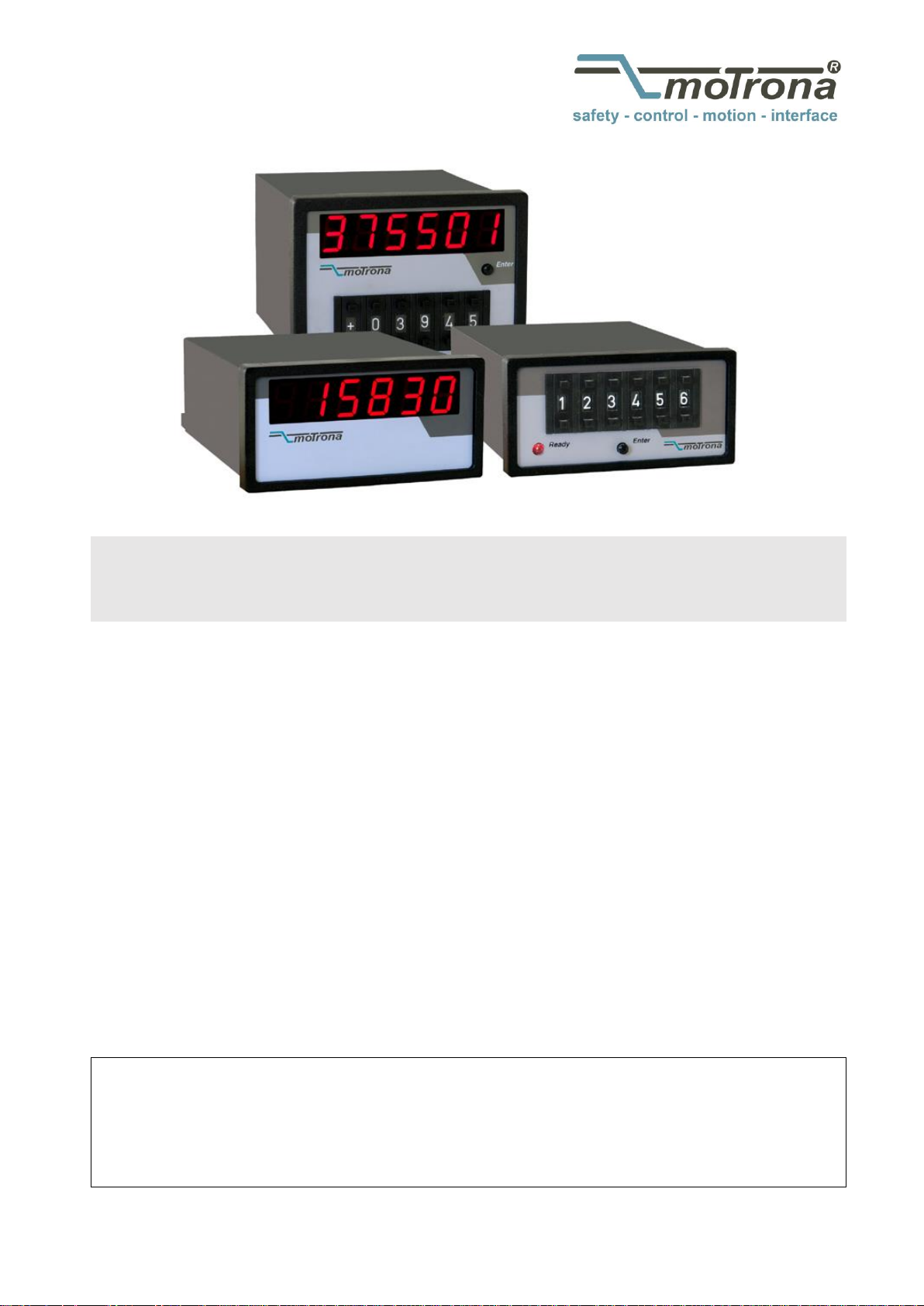
PB340 / PB306 / PB541
Process value indicators and data preset units for PROFIBUS-DP
Available Devices:
PB340: Display unit only
PB306: Preset unit only
PB541: Display / Preset combination
Product Features:
The PB340 variant is a simple indicator unit for remote display of all actual data
which are available on the connected PROFIBUS network. Arbitrary parameters or
actual values can be read or displayed.
PB306 is a simple data preset unit with front-sided thumbwheel switches. It
allows an easy remote setting of single parameters (e. g. speed setting of a drive)
via fieldbus. By pressing the ENTER button, the actual BCD setting will be
transmitted via PROFIBUS and hold in the polling register for readout.
PB541is a combination of preset switch and indicator. While the BCD switch
allows to make register changes via PROFIBUS, the LED display provides
information about the actual setting of the same or any other register value.
motrona GmbH, Zeppelinstraße 16, DE - 78244 Gottmadingen, Tel. +49 (0) 7731 9332-0, Fax +49 (0) 7731 9332-30, info@motrona.com, www.motrona.com
Page 2

Version:
Description:
PB34001c_hk_03/2008
motrona format A5, single language
Pb340_01d_oi_e.doc/Nov-15/ag
“Safety Instructions” and “Legal notices” supplemented
“Technical Specifications” and manual-design updated
Legal notices:
All contents included in this manual are protected by the terms of use and copyrights of motrona GmbH. Any
reproduction, modification, usage or publication in other electronic and printed media as well as in the internet
requires prior written authorization by motrona GmbH.
Table of Contents
1. Safety Instructions and Responsibility ......................................................... 3
1.1 General Safety Instructions ................................................................................... 3
1.2 Use according to the intended purpose ................................................................ 3
1.3 Installation ............................................................................................................. 4
1.4 Cleaning, Maintenance and Service Notes ........................................................... 4
2. Introduction ................................................................................................. 5
3. Block Diagram and Terminal Assignment ..................................................... 6
3.1. PROFIBUS connector pin assignment: ................................................................... 7
4. Transmission Baud Rate and Unit Address .................................................. 8
5. Communication ............................................................................................ 9
6. GSD-File .................................................................................................... 11
7. Technical Specifications ............................................................................ 14
8. Dimensions ................................................................................................ 15
8.1. PB306, PB340: ..................................................................................................... 15
8.2. PB541: .................................................................................................................. 15
Pb340_01d_oi_e.doc / Apr-16 Page 2 / 15
Page 3

1. Safety Instructions and Responsibility
1.1 General Safety Instructions
This operation manual is a significant component of the unit and includes important rules and
hints about the installation, function and usage. Non-observance can result in damage and/or
impairment of the functions to the unit or the machine or even in injury to persons using the
equipment!
Please read the following instructions carefully before operating the device and observe all
safety and warning instructions! Keep the manual for later use.
A pertinent qualification of the respective staff is a fundamental requirement in order to use
these manual. The unit must be installed, connected and put into operation by a qualified
electrician.
Liability exclusion: The manufacturer is not liable for personal injury and/or damage to property
and for consequential damage, due to incorrect handling, installation and operation. Further
claims, due to errors in the operation manual as well as misinterpretations are excluded from
liability.
In addition the manufacturer reserve the right to modify the hardware, software or operation
manual at any time and without prior notice. Therefore, there might be minor differences
between the unit and the descriptions in operation manual.
The raiser respectively positioner is exclusively responsible for the safety of the system and
equipment where the unit will be integrated.
During installation or maintenance all general and also all country- and application-specific
safety rules and standards must be observed.
If the device is used in processes, where a failure or faulty operation could damage the system
or injure persons, appropriate precautions to avoid such consequences must be taken.
1.2 Use according to the intended purpose
The unit is intended exclusively for use in industrial machines, constructions and systems. Nonconforming usage does not correspond to the provisions and lies within the sole responsibility
of the user. The manufacturer is not liable for damages which has arisen through unsuitable
and improper use.
Please note that device may only be installed in proper form and used in a technically perfect
condition - in accordance to the Technical Specifications (see chapter 7). The device is not
suitable for operation in explosion-proof areas or areas which are excluded by the EN 61010-1
standard.
Pb340_01d_oi_e.doc / Apr-16 Page 3 / 15
Page 4

1.3 Installation
The device is only allowed to be installed and operated within the permissible temperature
range. Please ensure an adequate ventilation and avoid all direct contact between the device
and hot or aggressive gases and liquids.
Before installation or maintenance, the unit must be disconnected from all voltage-sources.
Further it must be ensured that no danger can arise by touching the disconnected voltagesources.
Devices which are supplied by AC-voltages, must be connected exclusively by switches,
respectively circuit-breakers with the low voltage network. The switch or circuit-breaker must
be placed as near as possible to the device and further indicated as separator.
Incoming as well as outgoing wires and wires for extra low voltages (ELV) must be separated
from dangerous electrical cables (SELV circuits) by using a double resp. increased isolation.
All selected wires and isolations must be conform to the provided voltage- and temperatureranges. Further all country- and application-specific standards, which are relevant for structure,
form and quality of the wires, must be ensured. Indications about the permissible wire crosssections for wiring are described in the Technical Specifications (see chapter 7).
Before first start-up it must be ensured that all connections and wires are firmly seated and
secured in the screw terminals. All (inclusively unused) terminals must be fastened by turning
the relevant screws clockwise up to the stop.
Overvoltages at the connections must be limited to values in accordance to the overvoltage
category II.
For placement, wiring, environmental conditions as well as shielding and earthing/grounding of
the supply lines the general standards of industrial automation industry and the specific
shielding instructions of the manufacturer are valid. Please find all respective hints and rules on
www.motrona.com/download.html --> “[General EMC Rules for Wiring, Screening and
Earthing]”.
1.4 Cleaning, Maintenance and Service Notes
To clean the front of the unit please use only a slightly damp (not wet!), soft cloth. For the rear
no cleaning is necessary. For an unscheduled, individual cleaning of the rear the maintenance
staff or assembler is self-responsible.
During normal operation no maintenance is necessary. In case of unexpected problems, failures
or malfunctions the device must be shipped for back to the manufacturer for checking,
adjustment and reparation (if necessary). Unauthorized opening and repairing can have
negative effects or failures to the protection-measures of the unit.
Pb340_01d_oi_e.doc / Apr-16 Page 4 / 15
Page 5

2. Introduction
A printout of the GSD file necessary for the use of this unit can be found under
section 6. of this manual. The file itself is available on the CD supplied with
every unit.
You can also download this file at any time from the DOWNLOAD site of our
homepage: http://www.motrona.com
The PB340 / PB306 / PB541 series has been designed for display and/or remote preset of single
parameters or registers (e.g. display of actual position or preset of line speed) in systems using
a PROFIBUS-DP network.
These units operate as PROFIBUS-DP slaves according to EN 50 170.
PB340 is a display unit with a 6 decade, 15mm ( 0.59’’ ) size LED-display.
PB306 is a 6 decade BCD thumbwheel switch set with a range of 0 … 999 999 *).
PB541 is a combination of both, PB340 and PB306, providing a display and a BCD
thumbwheel switch set *).
All units are built into DIN housings for front panel mounting.
*) With supplementary ordering information “Option VZ000” the unit is available as a 5 decade plus sign
version (setting range -99999 to +99999)
Pb340_01d_oi_e.doc / Apr-16 Page 5 / 15
Page 6

3. Block Diagram and Terminal Assignment
12345678
ENTER
Potential
Separation
Power
10...30 V DC
RS485
Driver
DIL switch
BCD Data
3 4 521 6
Display
Processor and
Profibus controller
PB306, PB541
Power
Supply
5,0 V
3,3 V
PE
DC
DC
PB340, PB541
1M 2n5
DGND
Profibus
123 4 5 678
10...30 V DC
Power Supply
Profibus
PE
DIL-Switch
Sub-D 9 female
1
9
Power supply screw terminals, PROFIBUS connector and DIL switches for setup are located on
the backplane of the unit.
Pb340_01d_oi_e.doc / Apr-16 Page 6 / 15
Page 7

3.1. PROFIBUS connector pin assignment:
Pin:
Signal:
Function:
1
Screen
Screen / Earth connection
2
n. c.
–
3
RxD/TxD-P
Data +
4
CNTR-P (RTS)
Request To Send
5
DGND
Reference Potential (Ground)
6
VP
Power supply + 5 V / 50 mA
7
n. c.
–
8
RxD/TxD-N
Data -
9
n. c.
–
Impedance:
135 … 165
Capacitance:
< 30 pF / m
Loop resistance:
< 110 / km
Wire diameter:
> 0,64 mm (0.025’’)
Conductor cross section:
> 0,34 mm²
Baud rate (kbit / s)
9,6
19,2
93,75
187,5
500
1500
3000
6000
12000
Max. cable length (m)
1200
1000
400
200
100
The PROFIBUS line must be terminated by a resistor network on the extreme
ends of the cable (i.e. on the first unit and on the last unit).
The shield of the cable must be connected to protection earth.
220R
Last unit
screen
390R
390R
DGND
VP (+ 5 V)
First unit
220R
390R
390R
DGND
VP (+ 5 V)
RxD/TxD-P
RxD/TxD-N
Unit
The following cables are recommended for PROFIBUS (EN 50 170 “Type-A cable“):
Depending on the Baud rate, the following maximum cable length must not be exceeded:
Pb340_01d_oi_e.doc / Apr-16 Page 7 / 15
Page 8

4. Transmission Baud Rate and Unit Address
Device address
0 0 0 0 0 1 1
.
:
3
1:
123 4 5 67 8
ON (1)
OFF (0)
0 0 0 0 1 0 0
4
0 0 0 0 1 0 1
5
1 1 1 1 1 0 1
125
126
Thumbwheel switchset...
0:
signed (MSDigit + / -)
unsigned (MSDigit 0...9)
.
:
1 1 1 1 1 1 0
1 1 1 1 1 0 0
124
DIL switch settings are only read upon initialization. Changes during
normal operation will not be recognized! After change of DIL switch
settings you must therefore cycle the power supply of the unit.
The unit does not require a Baud rate preset because the baud rate of the network will be
automatically recognized while the communication is starting up. All PROFIBUS-DP baud rates
from 9.6 kbit/s to 12 Mbit/s are supported.
Positions 2…7 of the DIL switch select the unit address, value range 3…126. This address
cannot be changed by the master by the Set_Slave_Address service.
Switch position 1 defines the most significant digit of the front thumbwheel switches to be
transmitted as a numeral or a sign (PB306 and PB541 only).
Version providing a sign (option VZ000) require position 1 to be set to “ON”!
Pb340_01d_oi_e.doc / Apr-16 Page 8 / 15
Page 9

Unit Type:
Configuration Data:
Meaning:
PB340
A3 hex
4 byte output data
PB306
93 hex
4 byte input data
PB541
B3 hex
4 byte input data + 4 byte output data
status
wd_fact_1
wd_fact_2
tsdr
Ident high
Ident low
group_Ident
“decimal point”
PROFIBUS-DP parameter data ( EN 50 170)
1 byte user
parameter data
diag
1
diag
2
diag
3
diag
4
Ident
high
Ident
low
sign_len
= 05 hex
status_type
= 81 hex
slot_nr=
00
specifier
= 00
error
= XX
PROFIBUS-DP diagnosis data
( EN 50 170)
device specific diagnosis data
(“State PDU”)
5. Communication
During start-up of the communication the master must transmit the configuration data
according to the unit type:
When transmitting the parameter data to the unit, the position of the decimal point in display
can be set by the user parameter “decimal point”:
The diagnosis data provide 6 bytes of PROFIBUS-DP diagnosis data and 5 byte of device
specific diagnosis data
After successful start-up the data communication begins. Both input and output data are
transmitted as signed 32-bit data.
Received output data (PB340, PB541) will be displayed immediately. When the display value
range of -99999 … 999999 is exceeded, “------” will appear in the display.
With PB306 and PB541 units the data of the thumbwheel switch set will be transferred to the
input data buffer upon pressing the ENTER button, and then transmitted with the next cycle.
Pb340_01d_oi_e.doc / Apr-16 Page 9 / 15
Page 10

The actual communication state of the slave unit is indicated by display (PB340, PB541) or by
Display:
(PB340, PB541)
LED:
(PB306)
PROFIBUS-DP state:
Device state:
“ . . . . . . ”
off
Power_on
initialization
“ - - - - - - ”
flashing slowly
Wait_Prm
Wait_Cfg
Ready, waiting for start-up
“XXXXXX”
(output data)
on
Data_Exchange
Communication active
“_EXXX_”
flashing quickly
(Power_on)
Fatal Error
the front LED (PB306):
A fatal error can be reset only by switching of power supply.
Pb340_01d_oi_e.doc / Apr-16 Page 10 / 15
Page 11

6. GSD-File
;*********************************************************************
;
; GSD-File for PB340/306/541
;
; File: mksr0553.gsd
; Version: 02
; Date: 07.01.2008
; Author: Thomas Jaeckle
;
; motrona GmbH
; www.motrona.com
;
;*********************************************************************
;
;
#PROFIBUS_DP
;
;
; <Ext-User-Prm-Data-Def-List>
;
ExtUserPrmData = 1 "decimal point" ; User parameter: Display Decimal Point
Unsigned8 0 0-5 ; Default value: 0, value range: 0...5
EndExtUserPrmData
;
;
;General parameters:
;
GSD_Revision = 1
Vendor_Name = "motrona"
Model_Name = "PB340/306/541"
Revision = "01"
Ident_Number = 0x0553
Protocol_Ident = 0 ; PROFIBUS-DP
Station_Type = 0 ; Slave
FMS_supp = 0 ; No FMS supported
Hardware_Release = "340PB11"
Software_Release = "01"
Pb340_01d_oi_e.doc / Apr-16 Page 11 / 15
Page 12

;
9.6_supp = 1 ; Supported baud rates
19.2_supp = 1
93.75_supp = 1
187.5_supp = 1
500_supp = 1
1.5M_supp = 1
3M_supp = 1
6M_supp = 1
12M_supp = 1
;
MaxTsdr_9.6 = 60
MaxTsdr_19.2 = 60
MaxTsdr_93.75 = 60
MaxTsdr_187.5 = 60
MaxTsdr_500 = 100
MaxTsdr_1.5M = 150
MaxTsdr_3M = 250
MaxTsdr_6M = 450
MaxTsdr_12M = 800
;
Redundancy = 0
Repeater_Ctrl_Sig = 2 ; RTS-Signal (CNTR-P): TTL-level
24V_Pins = 0 ; No 24V supply on PROFIBUS-connector
Implementation_Type = "DPC31"
;
;
; Slave-Specification:
;
Freeze_Mode_supp = 1 ; Freeze-Mode supported
Sync_Mode_supp = 1 ; Sync-Mode supported
Set_Slave_Add_Supp = 0 ; Set_Slave_Address not supported
Auto_Baud_supp = 1 ; Automatic baudrate recognition
Min_Slave_Intervall = 10
Fail_Safe = 1 ; Fail-Save-Mode supported
Max_Diag_Data_Len = 11 ; 5 byte user diagnostic data
Modul_Offset = 0
Slave_Family = 6 ; HMI unit
Modular_Station = 1
Pb340_01d_oi_e.doc / Apr-16 Page 12 / 15
Page 13

Max_Module = 1 ; Modular station with one module
Max_Input_len = 4 ; 32 bit input data (PB306/541)
Max_Output_len = 4 ; 32 bit output data (PB340/541)
Max_Data_len = 8 ; Max. 2 * 32 bit data (PB541)
;
; UserPrmData:
;
Max_User_Prm_Data_Len = 1 ; 1 byte user parameter data
;
; Module Definition List:
;
Module="PB340" 0xA3 ; Config. PB340: 4 byte output data
Ext_Module_Prm_Data_Len = 1
Ext_User_Prm_Data_Const(0) = 0x00
Ext_User_Prm_Data_Ref(0) = 1
EndModule
;
Module="PB306" 0x93 ; Config. PB306: 4 byte input data
Ext_Module_Prm_Data_Len = 1
Ext_User_Prm_Data_Const(0) = 0x00
EndModule
;
Module="PB541" 0xB3 ; Config. PB541: 4 byte input data +
Ext_Module_Prm_Data_Len = 1 ; 4 byte output data
Ext_User_Prm_Data_Const(0) = 0x00
Ext_User_Prm_Data_Ref(0) = 1
EndModule
Pb340_01d_oi_e.doc / Apr-16 Page 13 / 15
Page 14

7. Technical Specifications
Power supply:
Input voltage:
Protection circuit:
Consumption:
PB306
PB340 / 541:
Connections:
10 … 30 VDC
reverse polarity protection
approx. 70 mA (at 24 V)
approx. 100 mA (at 24 V)
screw terminal, 1,5 mm² / AWG 16
Bus connection:
Communication profile:
Identity number:
Device data file:
Baud Rates (selectable):
PROFIBUS-DP Slave, EN 50 170
0553 hex
mksr0553.gsd
9.6 / 19.2 / 93.75 / 187.5 / 500 kbit/s,
1.5 / 3 / 6 / 12 Mbit/s
BCD switch PB306 / 541:
Adjustment range:
0 ... 999 999 (standard)
- 99 999 ... + 99 999 (Option VZ000)
Display PB340 / 541:
Range:
Type:
Digit height:
Number of digits:
- 99 999 ... 999 999
LED, red, seven segments
14 mm / 0.551 inch
6
Housing:
Material:
Mounting:
Dimensions:
PB306:
PB340:
PB541:
Protection class:
PB340*:
PB306* / 541:
Weight:
PB306 / 340:
PB541:
plastic
panel
outer dimensions (w x h x d):
96 x 48 x 120 mm / 3.78 x 1.89 x 4.72 inch
cut out (w x h): 92 x 43 mm / 3.62 x 1.69 inch
outer dimensions (w x h x d):
96 x 48 x 149 mm / 3.78 x 1.89 x 5.87 inch
cut out (w x h): 92 x 43 mm / 3.62 x 1.69 inch
outer dimensions (w x h x d):
96 x 72 x 149 mm / 3.78 x 2.83 x 5.87 inch
cut out (w x h): 92 x 67 mm / 3.62 x 2.64 inch
front side: IP 44 / rear: IP20
front side: IP 40 / rear: IP20
* IP 65 (front side) is available as an option
approx. 270 g
approx. 350 g
Temperature range:
Operation:
Storage:
0 °C … +45 °C / +32 … +113 °F (not condensing)
-25 °C … +70 °C / -13 … +158 °F (not condensing)
Failure rate:
MTBF in years:
PB340 : 55,9 a / PB306 : 59,1 a / PB541 : 43,5 a
(long-term usage at 60 °C / 140 °F )
Conformity & standards:
EMC 2004/108/EC:
Guideline 2011/65/EU:
EN 61000-6-2, EN 61000-6-3, EN 61000-6-4
RoHS-conform
Pb340_01d_oi_e.doc / Apr-16 Page 14 / 15
Page 15

8. Dimensions
8.1. PB306, PB340:
96,0 ( 3.780’’ )
48,0 ( 1.890’’ )
149,0 ( 5.866’’ )
42,5 ( 1.673’’ )
9,0 ( 0.354’’ )
8,0 ( 0.315’’)
Cut out: 92 x 43 mm ( 3.622 x 1.693’’ )
8.2. PB541:
96,0 ( 3.780’’ )
72,0 ( 2.835’’ )
149,0 ( 5.866’’ )
66,0 ( 2.598’’ )
9,0 ( 0.354’’ )
8,0 ( 0.315’’ )
Cut out: 92 x 67 mm ( 3.622 x 2.638’’ )
Pb340_01d_oi_e.doc / Apr-16 Page 15 / 15
 Loading...