

control – motion – interface
IX 345 - IX 348
SSI Indicators for Use with
Single-Turn or Multi-Turn SSI Encoders
motrona GmbH
Zwischen den Wegen 32
78239 Rielasingen - Germany
Tel. +49 (0)7731-9332-0
Fax +49 (0)7731-9332-30
info@motrona.com
www.motrona.com
IX 345: SSI display unit only
IX 346: SSI display unit with analogue output
IX 347: SSI display unit with two presets and outputs
IX 348: SSI display unit with serial interface RS232 and RS485
Clear LED display (15 mm / 0.59’’ size) with adjustable brightness
Master- or Slave operation with clock rates up to 1 MHz
Suitable for all SSI formats from 8 to 32 bits
Numerous supplementary functions like Linearization, Bit Blanking etc.
Operating Instructions
IX34510b_e.doc / Mrz-13 Page 1 / 43

Safety Instructions
Version:
Description:
This manual is an essential part of the unit and contains important hints about
function, correct handling and commissioning. Non-observance can result in
damage to the unit or the machine or even in injury to persons using the
equipment!
The unit must only be installed, connected and activated by a qualified electrician
It is a must to observe all general and also all country-specific and application-
specific safety standards
When this unit is used with applications where failure or maloperation could cause
damage to a machine or hazard to the operating staff, it is indispensable to meet
effective precautions in order to avoid such consequences
Regarding installation, wiring, environmental conditions, screening of cables and
earthing, you must follow the general standards of industrial automation industry
- Errors and omissions excepted –
General instructions for cabling, screening and grounding can be found in the
SUPPORT section of our website http://www.motrona.com
03b /af/hk//Feb 08 Range of PM-Factor, SSI zero position and preselection mode
1 / 2 increase to [-199999, 999999];
load on the current output max. 300 Ohm
07a = 08a/kk/hk/Apr.09 Extensions: Linearization, Activation of serial transmission
09a/kk/hk/Feb.10 Extension from 25 to 32 bits
10a/kk/hk/June.10 Missing encoder alarm, remote start of serial string
10b/af/nw/March 13 Correction of the basic parameter “Analogue Characteristics”
IX34510b_e.doc / Mrz-13 Page 2 / 43

Table of Contents
1. Terminal Assignment ................................................................................................... 4
1.1. Power Supply................................................................................................................................5
1.2. Aux. Voltage Output .....................................................................................................................5
1.3. Control Inputs A, B and C .............................................................................................................5
1.4. Adjustable Analogue Output (IX 346 only)...................................................................................6
1.5. Optocoupler (transistor) outputs (IX 437 only).............................................................................6
1.6. Serial RS232 / RS485 interface (IX 348 only) ..............................................................................7
2. How to Operate the Front Keys .................................................................................... 8
2.1. Normal display state ....................................................................................................................8
2.2. Selection and Setting of Parameters...........................................................................................9
2.3. Teach operation..........................................................................................................................10
2.4. Set all parameters to “Default“ .................................................................................................10
2.5. Code Locking of the Keypad.......................................................................................................10
3. The Operator Menu.................................................................................................... 11
3.1. Overview of Basic Parameters ...................................................................................................11
3.2. Overview of Operational Parameters.........................................................................................12
4. Setup Procedure......................................................................................................... 13
4.1. Basic Parameters........................................................................................................................13
4.2. Operational Parameters..............................................................................................................15
4.3. Additional Parameters for the Analogue Output (model IX 346)...............................................18
4.4. Additional Parameters for Preselections and Switching Outputs (model IX 347) ...................20
4.5. Additional Parameters for Units with Serial Interface (model IX 348).....................................22
5. Hints for Application .................................................................................................. 26
5.1. Master and Slave Operation ......................................................................................................26
5.2. Evaluation of Encoder Bits..........................................................................................................27
5.3. Scaling of the Display.................................................................................................................28
5.4. Basic Modes of Operation..........................................................................................................29
5.5. Testing Functions........................................................................................................................33
5.6. Error Messages...........................................................................................................................33
6. Special Functions....................................................................................................... 34
6.1. Linearization ...............................................................................................................................34
6.2. Manual Input or „Teaching“ of the Interpolation Points ...........................................................36
7. Technical Appendix.................................................................................................... 38
7.1. Dimensions .................................................................................................................................38
7.2. Technical Specifications.............................................................................................................39
7.3. Parameter-List ............................................................................................................................40
7.4. Commissioning Form ..................................................................................................................42
IX34510b_e.doc / Mrz-13 Page 3 / 43
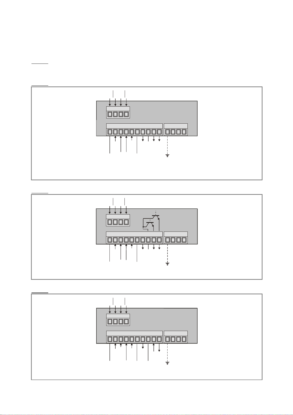
1. Terminal Assignment
10
C
L
KCL
KDA
T
D
A
T
10
GND
2
3
0
VAC11
5VA
C
0
V
ACC
LKC
LKD
ATD
A
T
10
CLK
CLK
DAT
DAT
IX 345: Display unit only
All connections are as shown below, except for terminals 8, 9 and 10 which are unconnected
IX 346: Display with analogue output
1 2 3 4
GND
230VAC
115 VAC
1 2 3 4 5 6 7 8 9
0 VAC
GND
17-30 VCD IN
Input A
Input B
Input C (Reset)
IX 347: Display with two presets and outputs
1 2 3 4
1 2 3 4 5 6 7 8 9
GND
17-30 VCD IN
Input A
Input B
Input C (Reset)
IX 348: Display with serial interface
GND
+24 VDC OUT
GND analogue
COM+
GND
+24 VDC OUT
PE
+/- 10 V analogue
0/4-20 mA analogue
OUT 1
OUT 2
PE
1 2 3 4
GND
230VAC
115 VAC
1 2 3 4 5 6 7 8 9
GND
Input B
Input C (Reset)
GND
+24 VDC OUT
17-30 VCD IN
InputA (transm.)
GND
PE
TxD / B (-)
RxD / A(+)
0 VAC
IX34510b_e.doc / Mrz-13 Page 4 / 43

1.1. Power Supply
The unit accepts DC supply from 17 V to 30 V when using terminals 1 and 2. The consumption
depends on the level of the supply voltage
(typical 130mA at 30V or 190mA at 17V, plus current taken from aux. output).
For AC supply the terminals 0 VAC, 115 VAC or 230 VAC can be used.
The total AC power is 7.5 VA.
The diagrams below show a dotted line for grounding to PE.
This connection is not really necessary, neither for safety nor for EMC. However, for some
applications, it may be desirable to ground the common potential of all signal lines.
When using this earthing option, please observe:
All terminals and potentials marked “GND“ will be earthed.
Please avoid multiple earthing, i.e. when you use a DC power supply where
the Minus is already connected to earth etc.
1.2. Aux. Voltage Output
Terminal 7 provides an auxiliary output of 24 VDC / 120 mA max. for supply of sensors and
encoders.
1.3. Control Inputs A, B and C
With models IX 348, input A is used to activate a serial transmission (rising edge, see 4.5.2).
Input B is not in use.
Input C operates as a Set / Reset input (static function, active "HIGH", see 5.3).
In the basic setup menu, the inputs can be configured to PNP (signal must switch to +) or to
NPN (signal must switch to -). This configuration is valid for all three inputs at a time.
The factory setting is always PNP.
Where NPN setting is used, please observe:
Open NPN inputs will always represent a logical HIGH state
Consequently, Input C has to be connected to GND externally to allow normal
operation. If unconnected, the unit would be kept in a continuous Reset state.
With models IX 348, also Input A must be tied to GND, and opening this connection will
generate a rising edge to start a serial transmission
Where your use 2-wire NAMUR type sensors, please select NPN, connect the negative
wire of the sensor to GND and the positive wire to the corresponding input.
IX34510b_e.doc / Mrz-13 Page 5 / 43
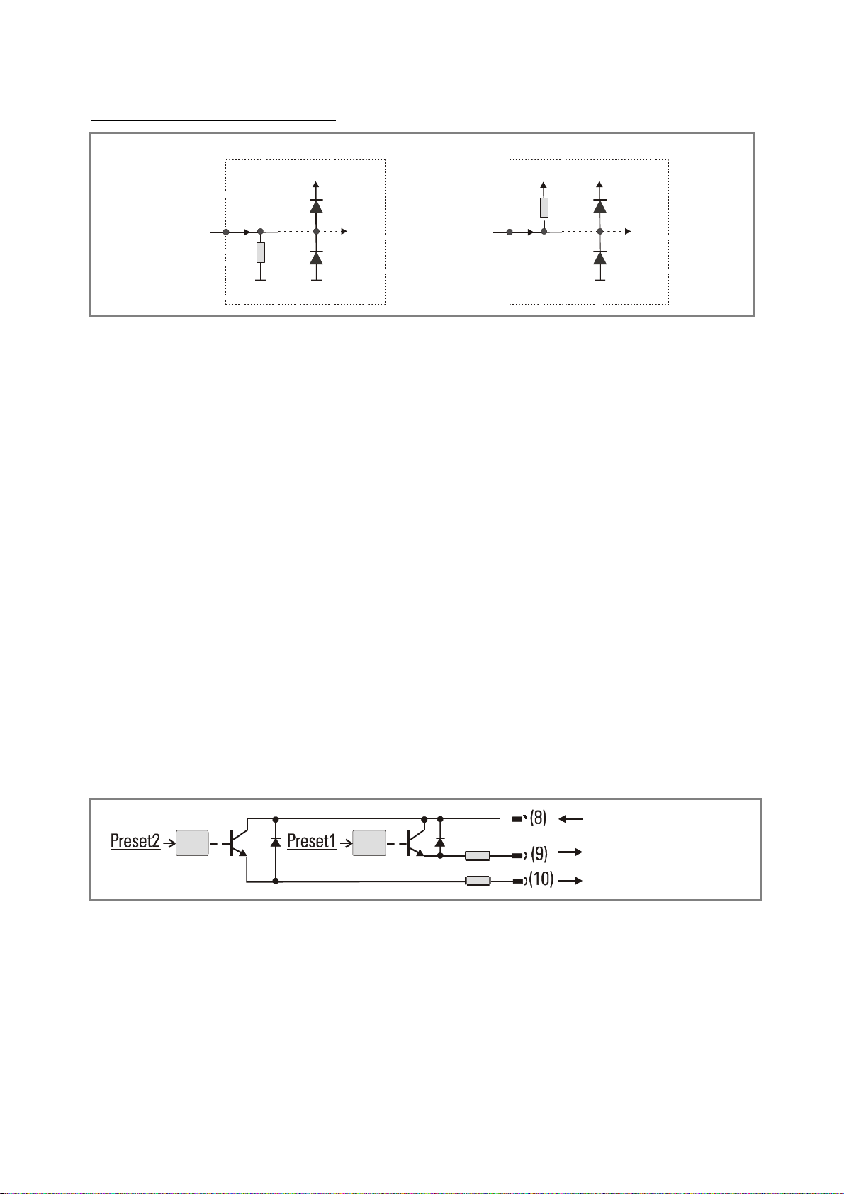
Typical input circuit of control input
PNP
GND
Input
+24V int.
NPN
Com+ (5 ... 35 V)
Output 1 (max. 150 mA)
Output 2 (max. 150 mA)
+24V int.
4,7k
Input
4,7k
GND GND
The minimum pulse duration on the Reset input (C) must be 5 msec.
1.4. Adjustable Analogue Output (IX 346 only)
A voltage output is available, operating in a range of 0 ... +10 V or –10 V ... +10 V according to
setting. At the same time, a current output 0/4 – 20 mA is available. Both outputs refer to the
GND potential and the polarity changes with the sign in the display. The outputs are
proportional to the display value and provide a 14 bits resolution.
The maximum current on the voltage output is 2 mA, and the load on the current output can
vary between 0 and max. 300 ohms.
The response time of the analogue output to changes of the encoder position is approx. 7 msec.
1.5. Optocoupler (transistor) outputs (IX 437 only)
The outputs provide programmable switching characteristics and are potential-free. Please
connect terminal 8 (COM+) to the positive potential of the voltage you like to switch
(range 5V....35V). You must not exceed the maximum output current of 150 mA. Where you
switch inductive loads, please provide filtering of the coil by means of an external diode.
The optocoupler outputs provide a response time of approx. 5 msec with resistive load.
Opto Opto
33 R
33 R
IX34510b_e.doc / Mrz-13 Page 6 / 43
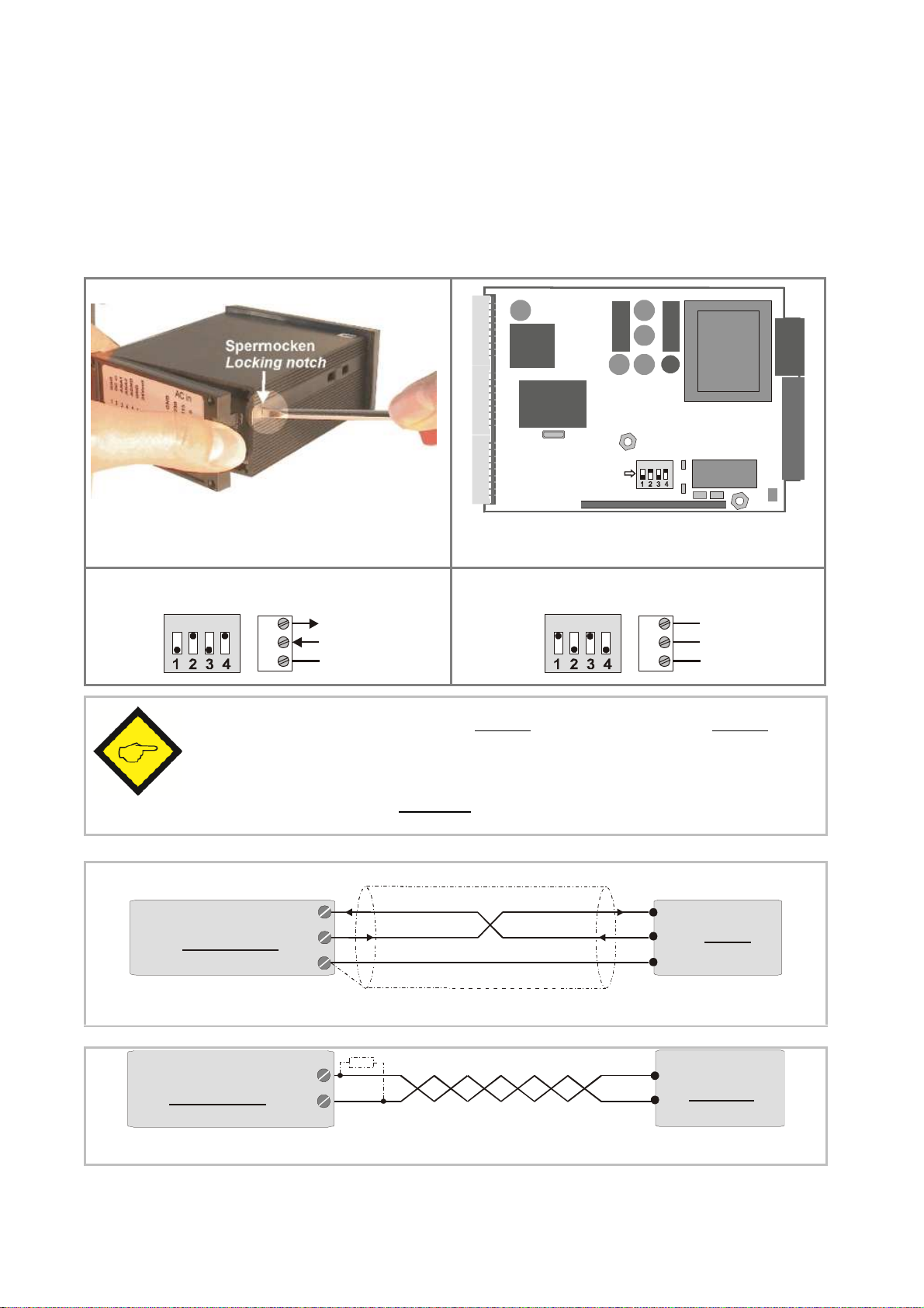
1.6. Serial RS232 / RS485 interface (IX 348 only)
ON DIP
DIL-Switch
8
910RxD
TxD
GND
8
910A (+)
B (-)
235
RxD
RxD
TxD
TxD
GND
Screen
PC
(Sub-D-9)
Conn
ection of the RS232 interface
PLC
Connection of the RS485 interface
Ex factory the unit is set to RS232 communication. This setting can be changed to RS485
(2-wire) by means of an internal DIL switch. To access the DIL switch, you must remove the
screw terminal connectors and the backplane. Then pull the board to the rear to remove the
PCB from the housing.
Removal of the back plane Location of the DIL switch
ON
RS232:
ON
RS485:
GND
Never set DIL switch positions 1 and 2 or DIL switch positions 3 and 4 to
“ON” at the same time!
After setting the switch, shift the print carefully back to the housing and
avoid damage of the front pins for connection to the front keypad plate.
9
IX 348
10
8
IX 348
IX34510b_e.doc / Mrz-13 Page 7 / 43
10
9
A(+)
B(-)
A(+)
B(-)
2. How to Operate the Front Keys
ENTER
SET
Cmd
Change over to
Key ope
ration
Basic setup
Keep
ENTER
and
SET
down simultaneously for 3 seconds
Operational
Keep
ENTER
down for 3 seconds.
Teach operation
Keep
Cmd
down for 3 seconds
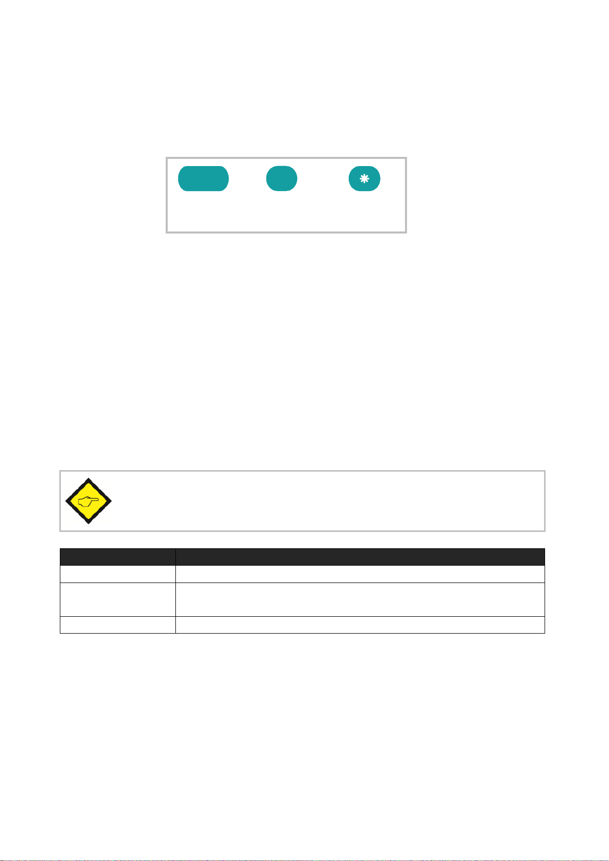
For setup and other operations the unit uses three front keys which subsequently will be
denominated as follows:
(Input)
The functions of the keys are depending on the actual operating state of the unit.
The following three operating states apply:
Normal display state
Setup state
a.) Basic setup
b.) Operational parameter setup
Teach operation
(Setting)
(Command)
2.1. Normal display state
You can only change over to other operation states while the unit is in the
normal display state.
parameter setup
The Cmd key is only used to execute the Teach procedure with linearization. For more details
please refer to sections 6.1 and 6.2.
IX34510b_e.doc / Mrz-13 Page 8 / 43

2.2. Selection and Setting of Parameters
2.2.1. How to select a parameter The ENTER key will scroll through the menu. The SET key allows to select the corresponding
item and to change the setting or the numeric value. After this, the selection can be stored by
ENTER again, which automatically changes over to the next menu item.
2.2.2. How to change parameter settings With numerical entries, at first the lowest digit will blink. When keeping the SET key
continuously down, the highlighted digit will scroll in a continuous loop from 0 … 9 , 0 … 9.
After releasing the SET key, the actual value will remain and the next digit will be highlighted
(blink). This procedure allows setting of all digits to the desired values. After the most
significant digit has been set, the low order digit will blink again and you can do corrections if
necessary.
With signed parameters, the high order digit will scroll from “0” to "9" (positive) followed by
“-“ and "-1" (negative)
2.2.3. How to store settings To store the actual setting, press the ENTER key, which will also automatically scroll forward
the menu.
At any time the unit changes from programming mode to normal display operation, when you
keep the ENTER key down again for at least 3 seconds.
2.2.4. Time-out function A “time-out” function will automatically conclude every menu level, when for a break period of
10 seconds no key has been touched. In this case, any changes which have not been confirmed
by ENTER yet would remain unconsidered.
IX34510b_e.doc / Mrz-13 Page 9 / 43
2.3. Teach operation
Key
Function
Cmd will store the display value to the register and will change over to the
The Time-out function will be switched off during all Teach operations
ENTER will conclude or abort any Teach operation in progress
SET function is fully similar to normal set-up operation
next interpolation point.
For details of the Teach procedure see section 6.2.
2.4. Set all parameters to “Default“
At any time you can return all settings to the factory default values.
The factory default settings are shown in the parameter listings in section 6.
When you decide to set all parameters to „default“, please be aware that all
previous settings will be lost and you will need to do the whole set-up
procedure once more
To execute the „Default“ setting function:
Power the unit down.
Press the ENTER key.
Power the unit up again while the ENTER key is kept down
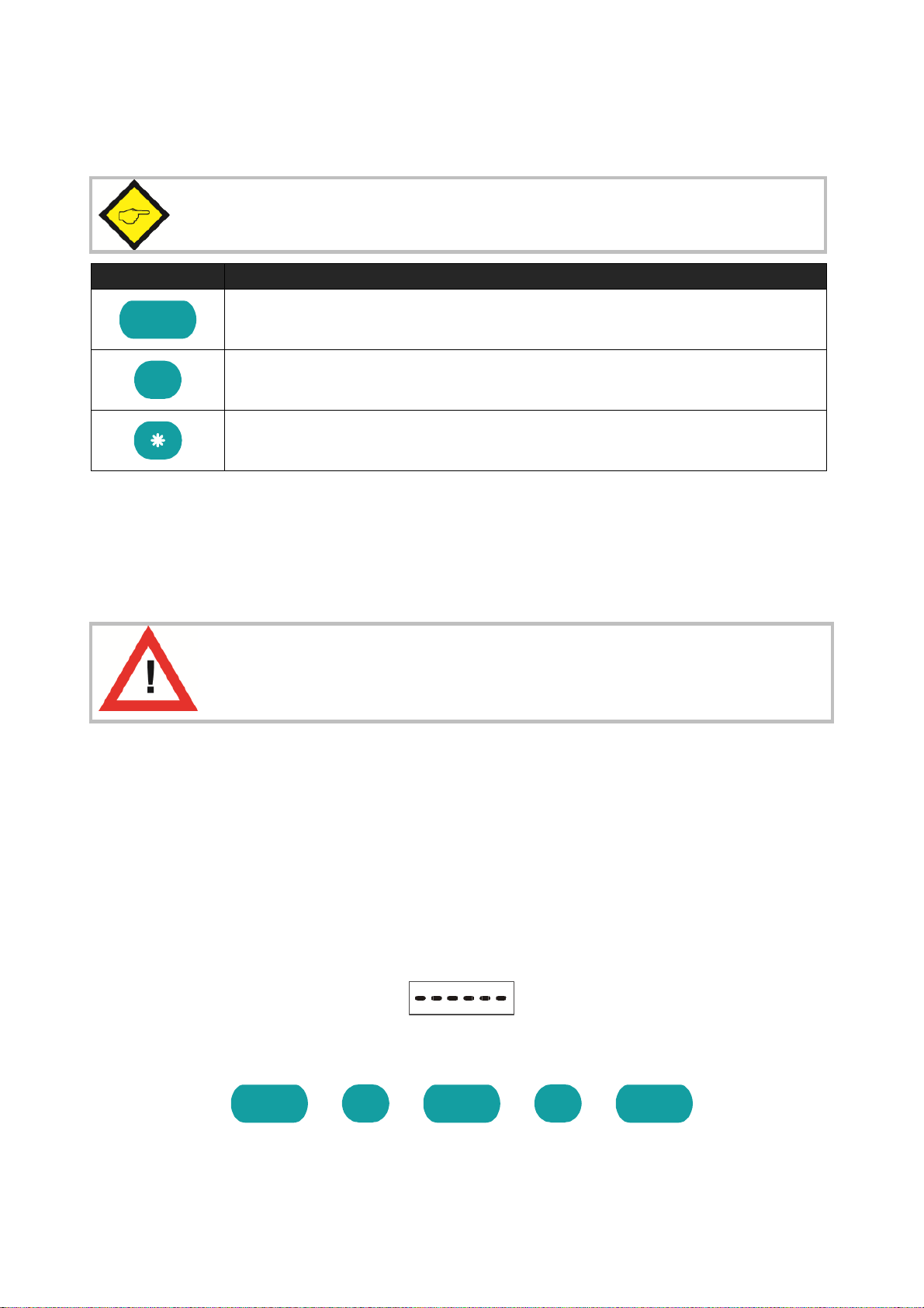
2.5. Code Locking of the Keypad
When the code locking of the keypad has been switched on, any key access first results in
display of
To access the menu you must press the key sequence
within 10 seconds, otherwise the unit will automatically return to the normal display mode.
IX34510b_e.doc / Mrz-13 Page 10 / 43

3. The Operator Menu
IX 345
IX 346
IX 347
IX 348
The menu provides one section with “Basic Parameters” and another section with “Operational
Parameters”. On the display you will only find those parameters which have been enabled by
the basic settings. E.g. when the Linearisation Functions have been disabled in the basic setup, the associated linearization parameters will also not appear in the parameter menu.
All parameters, as good as possible, are designated by text fragments. Even though the
possibilities of forming texts are very limited with a 7-segment display, this method has proved
to be most suitable for simplification of the programming procedure.
The subsequent table shows the general structure of the whole menu only.
Detailed descriptions of all parameters will follow in section 4.
3.1. Overview of Basic Parameters
SSI_Mode SSI_Mode SSI_Mode SSI_Mode
SSI_Bits SSI_Bits SSI_Bits SSI_Bits
SSI_Format SSI_Format SSI_Format SSI_Format
SSI_Baud Rate SSI_Baud Rate SSI_Baud Rate SSI_Baud Rate
SSI_Test SSI_Test SSI_Test SSI_Test
Characteristics Characteristics Characteristics Characteristics
Brightness Brightness Brightness Brightness
Code Locking Code Locking Code Locking Code Locking
Linearization Mode Linearization Mode Linearization Mode Linearization Mode
Analogue Characteristics Preselection_Mode 1 Ser_Unit_Nr
Analogue Offset Preselection_Mode 2 Ser_Format
Analogue Gain Hysteresis 1 Ser_Baudrate
Hysteresis 2
IX34510b_e.doc / Mrz-13 Page 11 / 43

3.2. Overview of Operational Parameters
IX 345
IX 346
IX 347
IX 348
Preselection 1
Preselection 2
M-Factor M-Factor M-Factor M-Factor
D-Factor D-Factor D-Factor D-Factor
P-Factor P-Factor P-Factor P-Factor
Decimal point Decimal point Decimal point Decimal point
Display Display Display Display
Hi_Bit (MSB) Hi_Bit (MSB) Hi_Bit (MSB) Hi_Bit (MSB)
Lo_Bit (LSB) Lo_Bit (LSB) Lo_Bit (LSB) Lo_Bit (LSB)
Direction Direction Direction Direction
Error Error Error Error
Error_Polarity Error_Polarity Error_Polarity Error_Polarity
Round Loop Round Loop Round Loop Round Loop
Time Time Time Time
Reset Reset Reset Reset
Zero Position Zero Position Zero Position Zero Position
Analogue Begin Ser_Timer
Analogue End Ser_Mode
Ser_Value
P01_X *) P01_X *) P01_X *) P01_X *)
P01_Y*) P01_Y*) P01_Y*) P01_Y*)
P16_X *) P16_X *) P16_X *) P16_X *)
P16_Y *) P16_Y *) P16_Y *) P16_Y *)
*) appears only when Linearization has been enabled in the Basic Menu
IX34510b_e.doc / Mrz-13 Page 12 / 43
4. Setup Procedure
Menu
Setting Range
Default
SSI-Bits
SSI-Format:
SSI-Baud Rate
SSI Test
Characteristics
*)
Brightness
For better understanding the following sections 4.1 and 4.2 explain settings for the display only.
Model-specific settings for Analogue Output, Preselections and Serial Link will be explained
separately, later.
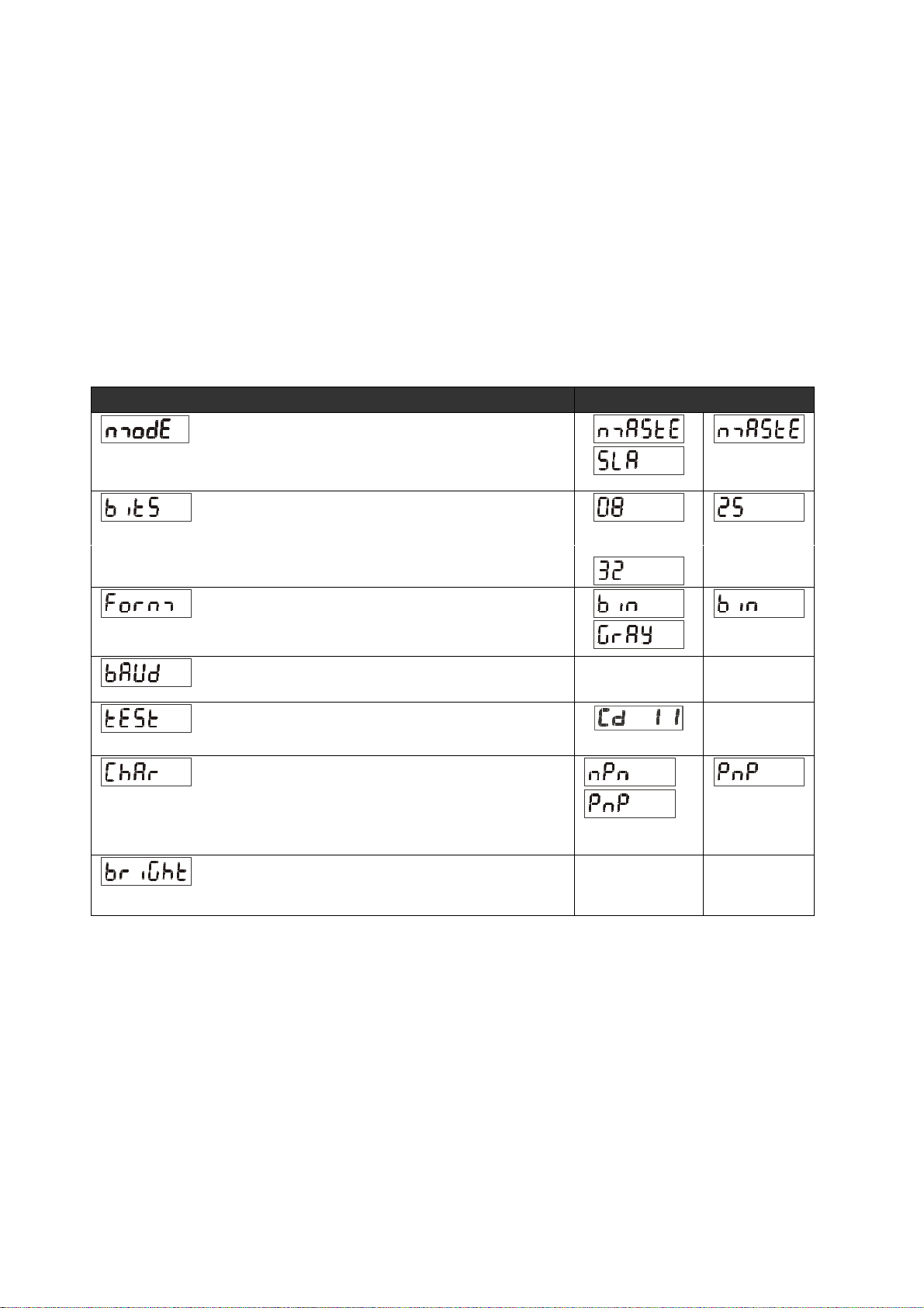
4.1. Basic Parameters
The subsequent settings are of unique nature and must only be made upon the very first setup.
The basic setup selects the desired operation mode of the unit, the input characteristics
PNP/NPN and the desired brightness of the LED display.
SSI-Mode
Setting of Master Mode or Slave Mode
For details see section 5.1
Bit length of the SSI string
For more details see section 5.2
Setting of the SSI code (Binary or Gray)
SSI Self test functions (see 5.5.)
Switching characteristics of the Reset input
NPN: switch to "-" *)
PNP: switch to "+"
Brightness of the 7-segment LED display
*) Please observe hints given in chapter 1.3
.....
0.1 ... 1000.9
kHz
etc.
20%, 40%, 60%
80% and 100%
100.0
kHz
100%
IX34510b_e.doc / Mrz-13 Page 13 / 43

Menu
Setting Range
Default
Code Locking
Interlock of keypad access (see 2.5)
Linearization Mode
no: Keypad accessible at any time
All: Keypad interlock for all functions
P-Free: Keypad interlock except for Preselection
Settings Pres 1 und Pres 2 (model IX 347)
For details please see 6.1 und 6.2.
no: Linearization is switched OFF *)
1-qua: Linearization settings for the positive range
only (negative values will appear as a mirror).
4-qua: Linearization over the full numeric range
*) The menu will not display any further linearization parameters
IX34510b_e.doc / Mrz-13 Page 14 / 43

4.2. Operational Parameters
Menu
Setting Range
Default
M-Factor *):
D-Factor *):
P-Factor *):
Decimal Point
Display:
Hi Bit **):
Lo Bit **):
Multiplying factor for the SSI value
(after consideration of possible bit blanking)
Dividing factor for the SSI value
(after consideration of possible bit blanking)
-9.999 … 9.999 1.000
0.001 … 9.999 1.000
This signed value will be added to the SSI result
(after consideration of possible bit blanking)
Setting according to the decimal formats shown in
the display
Display mode of the unit
norm: regular scaling of the display
359.59: Angular display format 359° 59' with use of
the Round Loop Function
Bit Blanking Function: Defines the highest bit for
evaluation. To evaluate all encoder bits this
parameter has to be set to the total number of bits
according to setting
-199999
…
999999
000000
00000.0
...
0.00000
norm
359.59
1 … 32 25
1 … 31 1
00000.0
norm
0
Bit Blanking Function: Defines the lowest bit for
evaluation. To evaluate all encoder bits this
parameter has to be set to "01"
*) Scaling details are explained under 5.3
**) For more details about Bit Blanking see 5.2
IX34510b_e.doc / Mrz-13 Page 15 / 43

Menu
Setting Range
Default
Direction
Parameter to negate the SSI value, resulting in
Error:
Error
-
Polarity *):
Round Loop
Time
reversal of the direction of the encoder count.
riGht: ascending values with forward motion
LEFt:: decreasing values with forward motion
riGht
LEFt
riGht
(please refer to 5.6)
Defines the control of presence of an encoder and
the location of the Error Bit in case of error.
00: No error bit available
Control of presence of an encoder is off
01: No error bit available
Control of presence of an encoder is on
>01: Location of the error bit
Control of presence of an encoder is on
Defines the polarity of the Error Bit in case of error.
0: Error Bit is Low in case of error
1: Error bit is High in case of error
When an error occurs, „Err-b“ appears on the display.
The same function can also be used to monitor the Power Failure Bit of an encoder
(mostly called „PFB“).
Defines the number of encoder steps per revolution
with use of the Round Loop Function (see 5.4.2).
0 ... 32 0
0
1
0 ... 999999 0
0
0: Normal display of the encoder data, no
Round Loop Function
>0: Number of steps per Round Loop Cycle
Sets the update cycle of the display (and of the
analogue output or the switching outputs where
applicable). The fastest possible update time is
3 msec. respectively one telegram length including 4
pause clocks. With Slave operation the next update
will occur when the unit synchronizes again to the
Master pause following to the expiration of the
update time.
0.000 ... 1.009
sec
0.01 sec
IX34510b_e.doc / Mrz-13 Page 16 / 43

Menu
Setting Range
Default
Reset
A Reset command is available to store the actual SSI
Zero Position:
*)
P01_X
**)
Linearization Point 1_X
P01_Y
Linearization Point 1_Y
…
P16_X
Linearization Point 16_X
P16_Y
Linearization Point 16_Y
position to register „Zero Position“. As a result, the
display value will become zero at the actual encoder
position, and all further operation will refer to this
new datum point. The zero position remains
memorized also after power-down.
no: Reset function disabled
Front: Reset function by the front SET key
E_tErn: Reset function by the remote Reset input
FR u E: Reset via key and remote input
-199999
Defines the zero position of the display. When you
set this parameter to e.g. "1024", the unit will
display zero when the encoder position is 1024.
Zero Position can be set directly via keypad or by
means of an external Reset command.
X value of the first interpolation point.
Y value of the first interpolation point.
X value of the 16. interpolation point.
Y value of the 16. interpolation point.
*) Please observe that Parameter P_Fac will cause an additional displacement of the zero position
**) Parameters P01_X to P16_Y appear only when the linearization has been enabled in the basic menu
...
999999
-199999
... 999999
-199999
... 999999
-199999
... 999999
-199999
... 999999
0
999999
999999
999999
999999
IX34510b_e.doc / Mrz-13 Page 17 / 43

4.3. Additional Parameters for the Analogue Output
Menu
Setting Range
Default
Analogue Characteristics
Analogue Offset:
Analogue Gain
:
Menu
Setting Range
Default
Analogue
-
Begin
Analogue
-
End
(model IX 346)
The following additional settings for the analogue output appear in the Basic Menu:
You can set the following output options:
+/- 10 V (bipolar),
0 - 10 V (positive only),
4 - 20 mA
0 - 20 mA.
With setting +/-10 Volts the polarity of the output
voltage will follow the sign in the display
-9,999..+9,999 0,000
Set this parameter to 0 when you expect your
analogue signal to start with 0 V (or 0 mA / 4 mA
respectively). Where another zero definition is
desired it can be set by this parameter. Setting of
e.g. 5.000 will already produce 5 volts with the
output in zero state.
00,00..99,99 10,00
Parameter to set the analogue output swing. Setting
10.00 will allow full swing of 10 V or 20 mA, setting
8.00 will reduce the swing to 8 V or 16 mA.
The following Operational Parameters provide scaling of the analogue output:
-199999...999999 0
Start value of the analogue conversion range
-199999...999999 100000
End value of the analogue conversion range
By means of these two parameters any window of the whole display range can be mapped onto
the analogue output.
IX34510b_e.doc / Mrz-13 Page 18 / 43

The subsequent example shows how to convert the display range from 1400 to 2000 into an
1000
2000
3000
4000
5000
SSI Display Value
AnalogueOutput
analogue signal of 2 - 10 volts.
Volts
10
8
6
4
2
A-ChAr = 0 - 10 V AnAbEG = 1400
OFFSEt = 2.000 AnAEnd = 2000
GAin = 8.00
All settings refer to the scaled values shown in the display of the unit,
and not to the original SSI encoder data
IX34510b_e.doc / Mrz-13 Page 19 / 43

4.4. Additional Parameters for Preselections and Switching Outputs
Menu
Default
HYSt 1
Hysteresis 1
HYSt 2
Hysteresis 2
(model IX 347)
The following additional settings for the Preselections appear in the Basic Menu:
Switching Characteristics of Output 1
Greater/Equal. Output to switch statically ON
when Display Value ≥ Preselection1
Lower/Equal. Output to switch statically ON
when Display Value ≤ Preselection1
Greater/Equal. Output to switch dynamically ON
when Display Value ≥ Preselection1
(timed output pulse) *)
Lower/Equal. Output to switch dynamically ON
when Display Value ≤ Preselection1
(timed output pulse) *)
Switching Characteristics of Output 2
See above, but Preselection2
See above, but Preselection2
See above, but Preselection2
See above, but Preselection2
Output to switch statically ON when
Display Value ≥ Preselection1 – Preselection2 **)
Output to switch dynamically ON when
Display Value ≥ Preselection1 – Preselection2 **)
Adjustable hysteresis for output 1
Setting range 0 ... 99999 display units
Adjustable hysteresis for output 2
Setting range 0 ... 99999 display units
*) Timed output pulses have a fixed duration of 500 msec (factory adjustable only)
**) Trailing Preset to generate an anticipation signal with a fixed distance to the main signal
0
0
IX34510b_e.doc / Mrz-13 Page 20 / 43

The following Operational Parameters provide setting of the switching thresholds:
Menu
Setting Range
Default
Preselection 1:
P
reselection 2:
Preselection
GE=Greater/Equal
Display Value
Preselection
LE=Lower/Equal
Hysteresis
Display
Meaning
Both outputs are actually OFF
Both outputs are actually ON
Output 1 is ON
Output 2 is OFF
Output 1 is OFF
Output 2 is ON
-199999..
999999
-199999..
999999
10000
5000
The direction of the Hysteresis effect depends on the setting of the switching characteristics.
With the settings „GE“ or „LE“ the following switch points will result:
Hysteresis
Hysteresis effect with "Greater / Equal"
Display Value
Hysteresis effect with "Lower / Equal"
It is possible to check up on the actual switching state of the outputs at any time.
For this, just tap on the ENTER key shortly.
The display will then show for the next two seconds one of the following information:
IX34510b_e.doc / Mrz-13 Page 21 / 43

4.5. Additional Parameters for Units with Serial Interface
Menu
Setting Range
Default
(model IX 348)
The following additional settings for serial communications appear in the Basic Menu:
Unit Number
You can assign any unit number between
11 and 99. The address must however not contain a
“0“ because such numbers are reserved for collective
addressing of several units.
Serial Data Format
The first character indicates the number of data bits.
The second character specifies the Parity Bit
„Even“, "Odd“ or no Parity Bit.
The third character indicates the number of Stop Bits.
0..99 11
Baud Rate
The following Baud Rates can be set for
communication:
IX34510b_e.doc / Mrz-13 Page 22 / 43

The following Operational Parameters provide configuration of the serial interface:
Menu
Setting Range
Default
Serial Timer:
Setting 0,000 allows manual activation of a serial data
transmission at any time. All other settings specify the cycle
time for automatic transmission, when the interface is set to
"Printer Mode"
Between two transmission cycles the unit will allow a pause
depending on the baud rate. The minimum cycle times for
timer transmissions are shown in the table.
Baud Rate Minimum Cycle Time [ms]
600 384
1200 192
2400 96
4800 48
9600 24
19200 12
38400 6
Serial Mode:
PC: Operation according to communication profile
(see 4.5.1)
Print1: Transmission of string type 1 (see 4.5.2)
Print2: Transmission of string type 2 (see 4.5.2)
0,000
0,010 sec
…
9.999 sec
0,100 sec
Serial Register-Code:
Specifies the register code of the data to be transmitted.
The most important register codes are:
Register S-Code ASCII Description
Original SSI
Value
SSI Value 113 ; 3 Encoder data after
Display
value
111 ; 1 Direct encoder data
Bit Blanking
101 : 1 Value with full scaling
as it appears in the
display
100
...
120
101
IX34510b_e.doc / Mrz-13 Page 23 / 43

4.5.1. PC-Mode
EOT
AD1
AD2
C1C2ENQ
EOT = Control Character (Hex 04)
ASCII
-
Code:
EOT11:1
ENQ
Hex:
0431313A3105Binary:
0000 0100
0011 0001
0011 0001
0011 1010
0011 0001
0000 0101
STXC1C2
x x x x x x x
ETX
BCC
STX = Control Character (Hex 02)
Communication with PC - Mode allows free readout of all parameters and registers of the unit.
The subsequent example shows the details of communication for serial readout of the actual
display value.
The general string to initiate a request has
the following format:
AD1 = Unit Address, High Byte
AD2 = Unit Address, Low Byte
C1 = Register Code, High Byte
C2 = Register Code, Low Byte
ENQ = Control Character (Hex 05)
Example:
Request string for readout of the actual display data from a unit with serial address No. 11:
With a correct request the unit will
respond with the adjoining response
string. Leading zeros will be suppressed.
BCC provides a „Block Check Character“,
formed by Exclusive-OR of all characters
from C1 through ETX.
C1 = Register Code, High Byte
C2 = Register Code, Low Byte
x x x x x = Data (display value)
ETX = Control Character (Hex 03)
BCC = Block Check Character
With inaccurate request strings the unit would only respond "STX C1 C2 EOT" or just "NAK".
IX34510b_e.doc / Mrz-13 Page 24 / 43

4.5.2. Printer Mode
„S-mod“
Transmission String Type
Space
Sign
Data
Line
Carriage
+/-XXXXXXLF
CR
Sign
Data
Carriage
+/-XXXXXXCR
Cyclic (timed)
Set the Serial Timer to any value
0.010 sec.
Manual activation of
Set the Serial Timer to 0.000.
The Printer Mode allows cyclic or manual activation of transmissions of the specified register
data. The corresponding register can be specified by means of parameter „S-Code“.
Another parameter named „S-mod“ allows selection between two different string types:
„Print1“
feed
return
„Print2“
return
The mode of activation of serial transmissions can be determined as follows:
≥
transmissions:
Select the desired string type by parameter "S-mod"
transmissions
After exit from the menu the transmissions will start automatically
Select the desired string type by parameter "S-mod"
After exit from the menu a transmission can be activated at any time
- by shortly pressing the ENTER key or
- by a rising edge to Control Input A
IX34510b_e.doc / Mrz-13 Page 25 / 43

5. Hints for Application
CLK
7 (+24V out)
SSI Encoder
SSI Indicator
Screen
DAT
DAT
SSI Indicator with Slave Operation
DAT
SSI Indicator
1000,0 kHz
888,0 kHz
800,0 kHz
7
27,0 kHz
666,0 kHz
615,0 kHz
571,0 kHz
533,0 kHz
500,0 kHz
470,0 kHz
444,0 kHz
421,0 kHz
400,0 kHz
380,0 kHz
363,0 kHz
347,0 kHz
333,0 kHz
320,0 kHz
307,0 kHz
296,0 kHz
285,0 kHz
275,0 kHz
266,0 kHz
258,0 kHz
250,0 kHz
5.1. Master and Slave Operation
Set register “Mode” to position “Master” when the unit should generate the clock signal for
the encoder. In this case the clock terminals (CLK) are configured as clock outputs.
(+24V)
Clock-
Clock+
DataData+
GND
(optional)
CLK
6 (GND)
SSI Indicator with Master Operation
When your encoder receives already its clock from another device and the unit should only
“listen” to the communication, then set register “Mode” to “Slave”. In this case, both clock
terminals (CLK) are configured as inputs.
Remote Master
+
Clock+
Clock-
SSI Encoder
ClockClock+
DataData+
-
Data+
Data-
Screen
CLK
CLK
DAT
6 (GND)
Set registers “Bits”, “Format” and “Baud” according to the encoder you use.
You are free to set any baud rate in a range from 0.1 kHz to 1000.0 kHz. For technical reasons
however, in the upper frequency range, the unit itself in master mode can only generate one of
the following Baud rates accurately:
IX34510b_e.doc / Mrz-13 Page 26 / 43

With Master operation, therefore other settings will result in generation of the next upper or
Requested
Usable Bits
lower value according to above list. With all settings <250.0 kHz the error between set rate and
generated rate becomes negligible.
It is mandatory to set the Baud rate also with Slave operation. In this case, however, the
setting serves only to determine the pause time for correct synchronization (pause is detected
after 4 clock cycles). The unit automatically synchronizes with every remote clock signal within
the specified Baud rate range.
5.2. Evaluation of Encoder Bits
This chapter explains the correlation between the Basic Parameter „BitS“ and the Operational
Parameters „Hi bit“ and „Lo bit“. The example below uses an encoder with 16 bits.
Unused Bits may be blanked out according to individual need
Whenever the number of bits (clock cycles) requested from the SSI Master is higher
than the real number of encoder bits, all excessive Bits must be blanked by
corresponding setting of parameters „Hi_bit“ and „Lo_bit“.
Basic Settings:
In general, parameter „BitS“ will always be set according to the real resolution of the encoder
(i.e. "BitS" = 16 with a 16 bit encoder). In this normal case the SSI telegram will not contain any
excessive bits.
With some applications (e.g. with Slave operation) it may however happen that the Master
transmits more clock cycles than the number of encoder bits (e.g. 21 clocks with a 16 bit
encoder). In such a case the master would always request 21 bits from the encoder, where the
encoder itself responds with 16 usable bits only, followed by 5 waste bits. These 5 excessive
bits must be blanked.
All standard SSI telegrams start with the most significant bit (MSB) and close with the least
significant bit (LSB). Unusable waste bits (X) will follow at the tail end. To blank these bits out,
in our example we would have to set „Hi bit“ to 21 and „Lo bit“ to 6 for proper evaluation of the
encoder information.
Hi Bit
Lo Bit
Bits (Clocks)
(encoder)
IX34510b_e.doc / Mrz-13 Page 27 / 43
21 20 19 18 17 16 15 14 13 12 11 10 9 8 7 6 5 4 3 2 1
16 15 14 13 12 11 10 9 8 7 6 5 4 3 2 1 X X X X X

5.3. Scaling of the Display
M-Factor
D-Factor
P-Factor
Under consideration of the scaling parameters which have been described previously, the final
display value of the unit results from
DISPLAY [Encoder SSI Data] [0-Position]
= - x
{ }
Encoder SSI data are always positive only. Where also negative values should be
indicated, this can be achieved by corresponding setting of the parameters
„0-Position“ or „P-Factor“
The LED display provides 6 decades. For this reason all parameter settings (including
0-Position) are also limited to a maximum range of 6 decades. SSI encoders with a
resolution of more than 19 bits will however generate SSI data with more than 6
decades. In such a case it can become difficult to set the 0-Position and the other
scaling parameters while the mechanical encoder position is in the overflow zone
(the unit would insistently display "overflow").
To avoid this kind of problem with encoders of more than 19 bits, we recommend to
use the Bit Blanking Function and evaluate 19 bits only
Where later you intend to use the "Round Loop" function, it is mandatory to blank all
unused bits.
Remote Reset/Set commands via keyboard or external input will overwrite the
current value of parameter „0-Position“ by the actual SSI position of the encoder.
Therefore, in the formula above, the content between the brackets { } will become
zero and the unit will display the same value as set to parameter „P-Factor“. This
scaling is also automatically stored to the Flash Prom for full data retention in powerdown state
+/-
IX34510b_e.doc / Mrz-13 Page 28 / 43

5.4. Basic Modes of Operation
M-Factor
:
1.000
Direction
:0D-Factor
:
1.000
Error
:
xxxP-
Factor
:0Error P
:
xxx
Decimal Point
:
000000
Round
-
Loop
:0Display
:0Time
:
xxx
Hi bit
:
Reset
:noLo bit
:0-
Position
:
0
5.4.1. Normal SSI display Normal operation provides calculation of the display value from the SSI encoder data and the
settings of the scaling factors. Negative values can be achieved by corresponding setting of the
zero-position, or by inversion of the direction bit.
To set the unit up without problem, it is best to use the following sequence of steps:
Set all basic registers according to the encoder type you use, as shown in section 4.1.
For better comprehension, use first all initial settings as shown in the list
(xxx = according to need)
see 5.2 and 5.3 *)
*) Please evaluate 19 bits only to avoid overflow
These settings ensure that the unit displays the pure SSI encoder information at first.
Move your encoder now from a “lower” position towards a “higher” position according
to your own definition of "low" and "high". When also the display changes from lower to
higher values, your own definition of directions matches with the encoder definition. If
not, change the setting of “Direction” from “0” to “1” now to receive the desired sense
of direction (changes after further parameter settings may cause different results) **)
Set the desired zero position, either by entering the numeric value to the “0-Position”
register, or by using the Reset function as described previously. Your zero definition will
divide the range into a positive and a negative zone.
At this time you are free to set all other registers according to your needs.
The subsequent drawings show the principle of evaluation with use of a 13 bit single turn
encoder, with the direction bit set to either “0” or to “1”, and with the zero position register
set to “1024” **)
**) Subject of correct sequence with parameter settings
IX34510b_e.doc / Mrz-13 Page 29 / 43

8192
Course of display with positive counting direction
Course of display with negative counting direction
7168
1024
Original encoder signal
Encoder 13Bit
Direction = 0
0-Position = 1024
Display
o
0
0-PoS = 1024
8192
1024
o
0
0-PoS = 1024
45
45
o
Original encoder signal
o
180 degrees
360
o
Encoder 13Bit
Direction = 1
0-Position = 1024
o
o
o
360180 degrees
-7168
IX34510b_e.doc / Mrz-13 Page 30 / 43
Display

5.4.2. Round-Loop Function
Round
-
Loop operation with 2048 steps / revolution when using of a 13 bit encoder
This mode of operation is used frequently with rotating round tables or similar applications,
where the absolute encoder information is only used for a limited and repeating range of the
encoder (like one revolution of the table, which must not at the same time mean one revolution
of the encoder shaft). The Round-Loop Function never uses any negative display values.
The Round-Loop Function allows assigning a programmable number of encoder steps to one full
360º rotation of the table. To avoid miscounting when passing the mechanical overflow of the
encoder range, the total encoder resolution should be an integer multiple of the number of
steps for one loop.
For setup, please proceed first like shown under section 5.4.1.
Then set register “r-LooP” to the number of steps corresponding to one revolution of the table.
You are free to scale the display to any engineering units desired, by setting the scaling factors
correspondingly.
Where you like to scale your display with the angular display format 359º59’, just change the
“Display” register from “0” to “359,59”. This will also automatically disable the general scaling
factors.
The subsequent diagram shows the round loop function with a 13 bit encoder, where one table
revolution corresponds to 2048 encoder steps and where the zero position is set to 1024.
8192
Original encoder signal
Round-Loop display
2048
1024
0 360
180
r-LooP = 20480-PoS = 1024
Encoder 13Bit
Direction = 0
0-Position = 1024
r-Loop = 2048
degrees
IX34510b_e.doc / Mrz-13 Page 31 / 43

5.4.3. Operation with Zero-Crossing
Overflow suppression w
ith a 13 bit SSI encoder
Master: bits 17 - 32
Slave: bits 01 - 16
As a special advantage, the round-loop mode can be used to bypass the mechanical encoder
overflow position, because in this mode the unit continues with steady operation, even while
the SSI encoder signal passes the mechanical overflow position from maximum to zero.
This feature can help to avoid mechanical adjusting of the encoder zero position with many
applications, when no other means for the mechanical zero definition is available.
In general the Reset input will be used to define the zero position. The following picture
explains the details of operation.
8192
Original encoder signal
Display
3500
Overflow
Encoder: 13 Bit
Direction = 0
r-LooP = 6000
0-PoS = 3500
o
0
0-PoS = 3500
r-LooP = 6000
360
o
degrees
5.4.4. Splitting of SSI Encoder Information into Two Separate Displays The Bit Blanking Function also allows to distribute one SSI telegram to two different SSI
indicator units. As a typical application the figure below shows how to separate the angular
information within one turn and the number of turns with a 16 x 16 Multiturn Encoder.
Multiturn SSI
16 + 16 = 32 Bit
(number of turns)
Parameters:
Bits = 32
HiBit = 32
LoBit = 17
(angular position)
Parameters:
Bits = 32
HiBit = 16
LoBit = 01
IX34510b_e.doc / Mrz-13 Page 32 / 43

5.5. Testing Functions
Menu
Selection
Text
Description
Cd (Clock
-
and data wiring test):
Cd (Clock
-
and data function test):
Menu
Description
The test menu can be accessed while doing the basic set up, as shown in section 4.1. Most of
these tests are for factory use only, but the following tests may also be helpful for the user:
When the wiring of clock line and data line is ok,
the display shows “Cd 11”. Display of “Cd 10”
means that the clock line is o.k. but the data wires
are false (wrong polarity) and "Cd 01" indicates a
problem with the clock lines.
With master mode, only the data lines are subject
of this test.
The next test generates clock and data signals and
feeds them directly into the rear terminals.
Therefore please remove the encoder connection.
“Cd iO” says that clock and data interface are all
right. and all other displays indicate a problem
with the SSI interface circuit.
5.6. Error Messages
The unit can detect and display the errors shown below. If you find an error message, please
check again the encoder wiring and the settings of all SSI-relevant parameters.
Overflow:
The selected SSI Baud Rate is too high.
Please set lower rate.
Error-bit: the error bit or the power failure bit of the encoder (PFB) is set
Error-time-out: with Slave mode, during the last 0.6 seconds (plus wait time setting)
the unit did not receive any valid data.
Error-Format: with Slave mode, a telegram with too short length has been received.
Missing encoder (1): right after power-up the unit detects that all SSI telegrams are
empty (all bits = 1)
Missing encoder (2): during normal operation the unit detects that regular SSI
telegrams are suddenly followed by empty telegrams (all bits = 1)
IX34510b_e.doc / Mrz-13 Page 33 / 43

6. Special Functions
y
xyLinearization Mode = 4_quA
P1(x)= -1000
6.1. Linearization
This function allows converting a non-linear input signal into a linear presentation or viceversa. There are 16 interpolation points available, which can be freely arranged over the whole
measuring range in any distance. Between two points the unit automatically will interpolate
straight lines.
It is advisable to set many points into areas with strong bending, and to use only a few points
in areas with little bending. „Linearisation Mode“ has to be set to either „1-quA“ or „4-quA“ to
enable the linearization function (see subsequent drawing).
Parameters P01_x to P16_x select 16 x- coordinates, representing the display values which the
unit would normally show in the display. With parameters P01_y to P16_y you can specify,
which values you would like to display instead of the corresponding _x values.
This means e.g. that the unit will replace the previous P02_x value by the new P02_y value.
With respect to the consistency of the linearization, the x- registers have to use continuously
increasing values, e.g. the x- registers must conform to the constraint
P01_X < P02_X < … < P15_X < P16_X.
Independent of the selected linearization mode, the possible setting range of all registers
P01_x, P01_y,…, P16_x, P16_y is always -199999 … 999999
With measuring values lower than P01_x the display will always be P01_y
With measuring values higher than P16_x, the display will always be P16_y.
P1(x)= 0
*)
*) Mirror of positive range
P1(y)= 0
Linearization Mode = 1_quA
P16(x)= 1000
P16(y)= 800
P1(y)= 900
P8(x)= 0
P8(y)= 750
x
P16(x)= +1000
P16(y)= - 600
IX34510b_e.doc / Mrz-13 Page 34 / 43

Application Example:
d
φ
(1-cos )
SSI Encoder
Display value
P01_xP0
5_xP1
6_x
SSI Data ( )
The picture below shows a Watergate where the opening is picked up by means of an SSI
encoder. We would like to display the clearance of the gate "d", but the existing encoder
information is proportional to the opening angle φ.
P16_y
Display (d)
d = d
0
φ
P15_y
P07_y
P05_y
P03_y
P01_y
φ
P03_x
P07_x
P15_x
IX34510b_e.doc / Mrz-13 Page 35 / 43

6.2. Manual Input or „Teaching“ of the Interpolation Points
Interpolation points to form the linearization curve can be entered one after another, using the
same procedure as for all other numeric parameters. This means you will enter all parameters
P01_x to P16_x and P01_y to P16_y manually by keypad.
During manual input of interpolation points the unit will not examine the settings
P01_x to P16_x. Therefore the operator is responsible for observation of the constraint
P01_X < P02_X < … < P15_X < P16_X.
In many cases it should however be much more convenient to use the Teach function.
For this we need to move the SSI encoder, step by step, from one interpolation point to the
next. Every time we enter the desired display value by keypad.
How to use the Teach Function:
Please select the desired range of linearization (see 4.1).
Hold down the “Cmd” key for 3 seconds, until the display shows “tEACh”. Now the unit
has switched over to the Teach mode. To start the teach procedure please press again
“Cmd” within the next 10 seconds. The display will then show “P01_X”.
With respect to the consistency required for linearization, all parameters from P01_X to
P16_Y will first be overwritten by suitable initial values. Initial values for „P01_X“ and
„P01_Y“ are -199999 and all other values will start with 999999.
Press once more “Cmd” to display the actual encoder position. Then move the encoder
to the first of the desired interpolation points
When you read the x-value of your first interpolation point in the display, press “Cmd”
again. This will automatically store the actual display value to the P01_x register. For
about 1 second you will read “P01_y “ on the display, followed by the same reading
again that has been stored previously
This display value now can be edited like a regular parameter, and you can change it to
the desired P01_y value
When you read the desired P01_y value in your display, store it by pressing “Cmd”
again. This will automatically cycle the display to the next interpolation point P02_x.
IX34510b_e.doc / Mrz-13 Page 36 / 43

Once we have reached and stored the last interpolation points P16_x/y, the routine will
restart with P01_x again. You are free to double-check your settings once more or to
make corrections.
To conclude the Teach procedure, keep ENTER down for about 2 seconds. In the display
you will read “StOP” for a short time, and then the unit returns to the normal operation.
At the same time all linearization points have been finally stored.
The unit will examine the constraint valid for the x-values of interpolation points. Every
interpolation point must be higher than its preceding point. Where this constraint is
breached, all 6 decimal points will blink automatically as a warning. Pressing the CMD key
will not store the illegal value, but result in an error text "E.r.r.-.L.O."
To exit the teach mode again, you have the following two possibilities:
1. Press the enter key for 2 seconds. On the display you will read “StOP” for a short time,
and then the unit will switch back to the normal mode.
2. Just do nothing. After 10 seconds the unit will switch back to the normal mode
automatically.
In both cases the parameters of linearization P01_X to P16_Y will not change.
IX34510b_e.doc / Mrz-13 Page 37 / 43

7. Technical Appendix
110,0 (4.331’’)
44,0(1.732)
48,0(1.890)
7.1. Dimensions
96,0 (3.780’’)
9,0 (.345)
8,0
(.315)
10,0
(.394)
129,0 (5.079)
140,5 (5.531)
91,0 (3.583)
Panel cut out: 91 x 44 mm (3.583 x 1.732’’)
IX34510b_e.doc / Mrz-13 Page 38 / 43

7.2. Technical Specifications
Supply voltage AC : 115/230 V (+/- 12.5 %)
Supply voltage DC : 24 V (17 – 30 V)
Consumption (without sensor) : 17 V: 190 mA, 24 V: 150 mA, 30 V: 120 mA
AC Power : 7.5 VA
Aux. output for encoder : 24 VDC, +/- 15%, 120 mA (with AC and DC supply)
Control Inputs : 3 inputs, A, B, C (PNP/NPN/Namur)
Input currents : 5.1 mA / 24 V (Ri = 4,7 kOhm)
Input level HTL : Low: 0 ... 2 V, High: 9 ... 35 V
SSI input frequency range : 100 Hz – 1 MHz
Min. pulse duration for Reset : 5 msec
Analogue output (IX 346) : 0/4 ... 20 mA (max. 300 ohms), 0...+/-10 V (max. 2 mA)
Resolution : 14 Bits + Sign
Accuracy : 0.1%
Serial interface (IX 348) : RS 232 / RS 485, 600 to 38 400 bauds
Ambient temperature : Operation: 0° - 45°C ( 32 – 113°F)
Storage: -25° - +70°C (-13 – 158°F)
Housing : Norly UL94 – V-0
Display : 6 decades, LED, high- efficiency orange, 15 mm (0.59’’)
Protection class : Front IP65, Rear IP20
Terminal cross section : Signals max. 1.5 mm², AC power max. 2.5 mm²
Switching outputs (IX 347) : PNP, max. 35 volts, max. 150 mA
Conformity and Standards : EMC 2004/108/EC: EN 61000-6-2
EN 61000-6-3
LV 2006/95/EC: EN 61010-1
IX34510b_e.doc / Mrz-13 Page 39 / 43

7.3. Parameter-List
Min
-
Max
-
Default
-
Ser.
NPN / PNP
CHAr
0111005Brightness
briGht
0401006Code Locking
Code
0201007SSI-Mode
modE
0101000SSI-Bits
bitS0832252001
SSI-Format
Form
0101002SSI-
Baudrate
bAUd
0.1
1000.9
100.0
5103
SSI-Test
tESt
0201004M-Factor
mFAc
-
9.999
+9.999
1.000
+/-4308D-
Factor
dFAc
0.001
9.999
1.000
4309P-
Factor
PFAc
-
199999
+999999
0+/-6010Decimal Point
dPoint
0501011Display
diSPLA
0101012Hi_Bit MSB
Hi_bit
132252013Lo_Bit LSB
Lo_bit
13112014Direction
dir0101015
Error Bit
Error
03202016Error Polarity
ErrorP
0101017Round Loop
r-looP
0
999999
06018Wait Time
timE
0.000
1.009
0.010
4319
Reset
FE
rES0301020
Zero Positionn
0-PoS-199999
+999999
0+/-6021Preselection 1
PrES 1
-
199999
+999999
10000
+/-6027
Preselection 2
PrES 2
-
199999
+999999
5000
+/-6028
Presel. Mode 1
CHAr 1
03010
29
Presel. Mode 2
CHAr 2
0501030Hyst
eresis 1
Hyst1
0
99999
05036Hysteresis 2
Hyst2
0
99999
05037Analogue Begin
An-bEG-199999
999999
0+/-6031Analogue End
An-End-199999
999999
100000
+/-6032
Analogue Mode
A-CHAr
0301033Offset
OFFSEt
-
9,999
+9,999
0,000
+/-4334
Gain
GAin
00,00
99,99
10,00
4235
Denomination Text
Value
Value
Value
Positions Characters
Code
IX34510b_e.doc / Mrz-13 Page 40 / 43

Denomination Text
Min
-
Max
-
Default
-
Ser.
Ser. Format
S-Form
0901092Baud Rate
S-bAUd
0601091Ser. Address
S-Unit
099112090Ser. Timer
S-tim109999
1004338
Ser. Mode
S-mod
0201039Register
-
Code
S-CodE
100
120
1013040Linear. Mode
LinEAr
02010D2Linear. Point 1
P01_H
-
199999
999999
999999
+/-60A0
P01_Y
-
199999
999999
999999
+/-60A1
Linear. Point 2
P02_H
-
199999
999999
999999
+/-60A2
P02_Y
-
199999
999999
999999
+/-60A3
Linear. Point 3
P03_H
-
199999
999999
999999
+/-60A4
P03_Y
-
199999
999999
999999
+/-60A5
Linear. Point 4
P04_H
-
199999
999999
999999
+/-60A6
P04_Y
-
199999
999999
999999
+/-60A7
Linear. Point 5
P
05_H
-
199999
999999
999999
+/-60A8
P05_Y
-
199999
999999
999999
+/-60A9
Linear. Point 6
P06_H
-
199999
999999
999999
+/-60B0
P06_Y
-
199999
999999
999999
+/-60B1
Linear. Point 7
P07_H
-
199999
999999
999999
+/-60B2
P07_Y
-
199999
999999
999999
+/-60B3
Linear. Point 8
P08_H
-
199999
999999
999999
+/-60B4
P08_Y
-
199999
999999
999999
+/-60B5
Linear. Point 9
P09_H
-
199999
999999
999999
+/-60B6
P09_Y
-
199999
999999
999999
+/-60B7
Linear. Point 10
P10_H
-
199999
999999
999999
+/-60B8
P10_Y
-
199999
999999
999999
+/-60B9
Linear. Point 11
P11_H
-
199999
999999
999999
+/-60C0
P11_Y
-
199999
999999
999999
+/-60C1
Linear. Point 12
P12_H
-
199999
999999
999999
+/-60C2
P12_Y
-
199999
999999
999999
+/-60C3
Linear. Point 13
P13_H
-
199999
999999
999999
+/-60C4
P13_Y
-
199999
999999
999999
+/-60C5
Linear. Point 14
P14_H
-
199999
999999
999999
+/-60C6
P14_Y
-
199999
999999
999999
+/-60C7
Linear. Point 15
P15_H
-
199999
999999
999999
+/-60C8
P15_Y
-
199999
999999
999999
+/-60C9
Linear. Point 16
P16_H
-
199999
999999
999999
+/-60D0
P16_Y
-
199999
999999
999999
+/-60D1
Value
Value
Value
Positions Characters
Code
IX34510b_e.doc / Mrz-13 Page 41 / 43

7.4. Commissioning Form
Date Software:
Operator: Serial Number:
General Setting: SSI-Mode: SSI-Bits:
SSI-Format: SSI-Baud Rate (kHz):
SSI-Test:
Characteristics: Brightness
Code Locking: Linearization Mode:
Model IX 346 Output Char.: Analogue Offset:
Analogue Gain:
Model IX 347 Presel. Mode 1 Presel. Mode 2:
Hysteresis 1 Hysteresis 2:
Model IX 348 Serial Unit Nr: Serial Format:
Serial Baud Rate:
Display-Parameters M-Factor: Decimal Point:
D-Factor: Display:
P-Factor:
SSI-Special: SSI-High bit: (MSB): SSI-Error bit:
SSI-Low bit: (LSB): SSI-E-Bit Polarity
SSI-Direction:
SSI-Round Loop: SSI-Reset Function:
SSI-Gap Time: SSI-Offset:
Zusatz-Parameter:
Model IX 346 Analogue Begin: Analogue End:
Model IX 347 Preselection 1: Preselection 2:
Model IX 348 Serial Timer: Serial Printer Mode:
Serial Register Code:
IX34510b_e.doc / Mrz-13 Page 42 / 43

Linearization
P1(x): P1(y): P9(x): P9(y):
P2(x): P2(y): P10(x): P10(y):
P3(x): P3(y): P11(x): P11(y):
P4(x): P4(y): P12(x): P12(y):
P5(x): P5(y): P13(x): P13(y):
P6(x): P6(y): P14(x): P14(y):
P7(x): P7(y): P15(x): P15(y):
P8(x): P8(y): P16(x): P16(y):
IX34510b_e.doc / Mrz-13 Page 43 / 43
 Loading...