

Page 1
Operating Manual
BG230
Programming and display unit for motrona safety units
Product features:
Touchscreen with intuitive navigation
1.54“ OLED Display (128 x 64 pixel)
Simple parameterization of motrona safety units
Editing, saving and loading of parameters
Dual channel frequency indicator
Individual scalable process and speed monitors
motrona GmbH, Zwischen den Wegen 32, DE - 78239 Rielasingen, Tel. +49 (0) 7731 9332-0, Fax +49 (0) 7731 9332-30, info@motrona.com, www.motrona.com
Page 2

Version:
Description:
Bg230_01a_oi_e/ag/12/14
First edition pre series
Bg230_02a_oi_e/sn-ag/06/15
First edition series
Legal notices:
All contents included in this manual are protected by the terms of use and copyrights of motrona GmbH. Any
reproduction, modification, usage or publication in other electronic and printed media as well as in the internet
requires prior written authorization by motrona GmbH.
Bg230_02a_oi_e.doc / Jun-15 Page 2 / 30
Page 3

Bg230_02a_oi_e.doc / Jun-15 Page 3 / 30
Page 4

Table of Contents
1. Safety Instructions and Responsibility ......................................................... 6
1.1. General Safety Instructions ................................................................................... 6
1.2. Use according to the intended purpose ................................................................ 6
1.3. Installation ............................................................................................................. 7
1.4. Cleaning, Maintenance and Service Notes ........................................................... 7
2. Functional Description ................................................................................. 8
3. Mounting On Safety Unit ............................................................................. 9
4. Electrical Connections ............................................................................... 10
4.1. 8-pin (male) connector ......................................................................................... 10
4.2. USB 2.0 Interface ................................................................................................ 10
5.1. Unit Mode „NORMAL OPERATION“ ................................................................... 12
5.1.1. Display 1: Frequencies (Hz) ................................................................................. 12
5.1.2. Display 2: Divergence (%) ................................................................................... 12
5.1.3. Display 3: Scaled Input 1 ..................................................................................... 12
5.1.4. Display 4: Scaled Input 2 ..................................................................................... 12
5.2. Modus „FACTORY SETTINGS“ ............................................................................ 13
5.3. „PROGRAMMING MODE“ ................................................................................... 14
5.3.1. BG230 Menu Structure ........................................................................................ 14
5.3.2. Menu Structure of the Safety Unit ...................................................................... 15
5.4. Load Parameter ................................................................................................... 16
5.4.1. Parameters of the Safety Unit ............................................................................. 16
5.4.2. BG230 Parameters ............................................................................................... 16
5.5. Edit Parameter ..................................................................................................... 17
5.6. Save Parameter ................................................................................................... 18
5.6.1. Save Parameter to Safety Unit ............................................................................ 18
5.6.2. Save Parameter to Display Unit .......................................................................... 18
5.6.3. Storage Hints ....................................................................................................... 18
5.7. PIN Value ............................................................................................................. 19
Bg230_02a_oi_e.doc / Jun-15 Page 4 / 30
Page 5

6. Parameterization via PC by using OS-6 ...................................................... 20
7. BG230 Parameter List ................................................................................ 21
7.1. Input Scaling for Display 3 and 4 ........................................................................ 22
7.2. Unit Settings ........................................................................................................ 23
7.3. Serial Settings ..................................................................................................... 24
8. Example of an individual scalable Display ................................................. 25
9. Error Messages ......................................................................................... 26
9.1. Error Messages from the Safety Unit.................................................................. 26
9.2. Status Messages from the BG230 ...................................................................... 27
10. Technical Specifications ............................................................................ 28
10.1. Dimensions .......................................................................................................... 29
11. Installation Form ........................................................................................ 30
Bg230_02a_oi_e.doc / Jun-15 Page 5 / 30
Page 6

1. Safety Instructions and Responsibility
1.1. General Safety Instructions
This operation manual is a significant component of the unit and includes important rules and hints
about the installation, function and usage. Non-observance can result in damage and/or
impairment of the functions to the unit or the machine or even in injury to persons using the
equipment!
Please read the following instructions carefully before operating the device and observe all safety
and warning instructions! Keep the manual for later use.
A pertinent qualification of the respective staff is a fundamental requirement in order to use these
manual. The unit must be installed, connected and put into operation by a qualified electrician.
Liability exclusion: The manufacturer is not liable for personal injury and/or damage to property
and for consequential damage, due to incorrect handling, installation and operation. Further claims,
due to errors in the operation manual as well as misinterpretations are excluded from liability.
In addition the manufacturer reserve the right to modify the hardware, software or operation
manual at any time and without prior notice. Therefore, there might be minor differences between
the unit and the descriptions in operation manual.
The raiser respectively positioner is exclusively responsible for the safety of the system and
equipment where the unit will be integrated.
During installation or maintenance all general and also all country- and application-specific safety
rules and standards must be observed.
If the device is used in processes, where a failure or faulty operation could damage the system or
injure persons, appropriate precautions to avoid such consequences must be taken.
1.2. Use according to the intended purpose
The unit is intended exclusively for use in industrial machines, constructions and systems. Nonconforming usage does not correspond to the provisions and lies within the sole responsibility of
the user. The manufacturer is not liable for damages which has arisen through unsuitable and
improper use. Please note that device may only be installed in proper form and used in a
technically perfect condition - in accordance to the technical specifications (see chapter 10). The
device is not suitable for operation in explosion-proof areas or areas which are excluded by the EN
61010-1 standard.
Bg230_02a_oi_e.doc / Jun-15 Page 6 / 30
Page 7

1.3. Installation
The device is only allowed to be installed and operated within the permissible temperature range.
Please ensure an adequate ventilation and avoid all direct contact between the device and hot or
aggressive gases and liquids.
Before installation or maintenance, the unit must be disconnected from all voltage-sources. Further
it must be ensured that no danger can arise by touching the disconnected voltage-sources.
Devices which are supplied by AC-voltages, must be connected exclusively by switches,
respectively circuit-breakers with the low voltage network. The switch or circuit-breaker must be
placed as near as possible to the device and further indicated as separator.
Incoming as well as outgoing wires and wires for extra low voltages (ELV) must be separated from
dangerous electrical cables (SELV circuits) by using a double resp. increased isolation.
All selected wires and isolations must be conform to the provided voltage- and temperatureranges. Further all country- and application-specific standards, which are relevant for structure,
form and quality of the wires, must be ensured. Indications about the permissible wire crosssections for wiring are described in the technical specifications (see chapter 10).
Before first start-up it must be ensured that all connections and wires are firmly seated and
secured in the screw terminals. All (inclusively unused) terminals must be fastened by turning the
relevant screws clockwise up to the stop.
Overvoltages at the connections must be limited to values in accordance to the overvoltage
category II.
For placement, wiring, environmental conditions as well as shielding and earthing/grounding of the
supply lines the general standards of industrial automation industry and the specific shielding
instructions of the manufacturer are valid. Please find all respective hints and rules on „
www.motrona.com/download.html --> [General EMC Rules for Wiring, Screening and Earthing]”.
1.4. Cleaning, Maintenance and Service Notes
To clean the front of the unit please use only a slightly damp (not wet!), soft cloth. For the rear no
cleaning is necessary. For an unscheduled, individual cleaning of the rear the maintenance staff or
assembler is self-responsible.
During normal operation no maintenance is necessary. In case of unexpected problems, failures or
malfunctions the device must be shipped for back to the manufacturer for checking, adjustment or
reparation. Unauthorized opening and repairing can have negative effects or failures to the
protection-measures of the unit.
Bg230_02a_oi_e.doc / Jun-15 Page 7 / 30
Page 8

2. Functional Description
The optional BG230 unit serves as programming- and display-unit for motrona safety-relevant
devices. With its intuitive operation, the BG230 is quick, easy and flexible to handle.
The unit can be used via PC or directly connected with the safety unit. The BG230 offers a wide
range of functions and features.
Applications with the safety unit:
Edit and save BG230 parameters
Edit and save parameters of safety units
Copy parameters of safety units
Dual channel frequency indicator
Individual scalable indication of e. g. speed, production rates, …
Visual error message
Applications via PC (still not available):
Edit and save BG230 parameters
In connection with a motrona safety unit, the functionality of the BG230 depends on the DIL-switch
setting of the safety unit. There are three different operation modes available:
„Normal Operation“ (see chapter 5.1)
„Factory Settings“(see chapter 5.2)
„Programming Mode“ (see chapter 5.3)
Bg230_02a_oi_e.doc / Jun-15 Page 8 / 30
Page 9
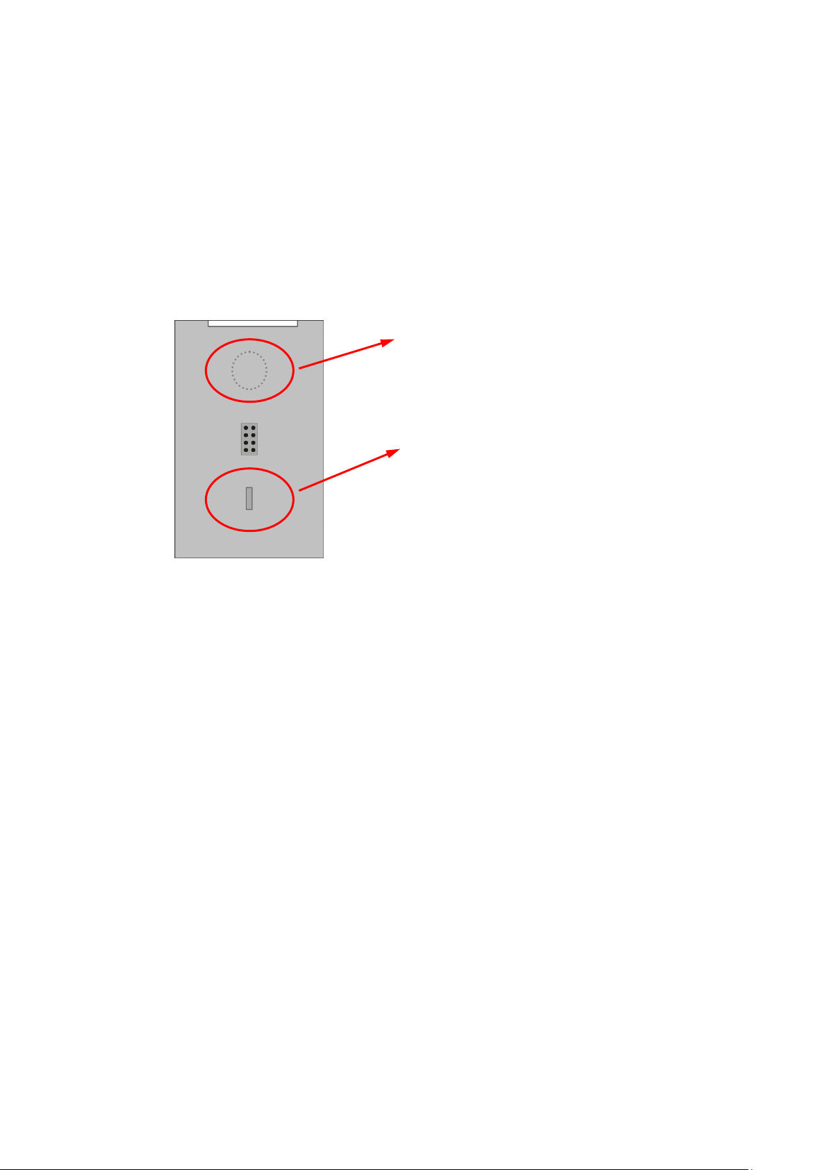
Rear view
Neodym-Magnet:
Neodym-Magnet for safety mounting.
Polarity protection:
Mechanical polarity protection.
3. Mounting On Safety Unit
The mounting of the programming unit BG230 can be done by simply plugging the programming
unit at the safety device. Via the 8-position pin strip both units will be connected. A mechanical
polarity protection ensures that the device cannot be plugged wrong. Neodymium magnets ensure
a safe mechanical connection.
Bg230_02a_oi_e.doc / Jun-15 Page 9 / 30
Page 10

Rear view
8-pin (male) connector:
This interface connects
the BG230 to the safety unit.
After initialization parameters
can be loaded, edited and saved.
Bottom view
USB 2.0 Interface: (still not available)
Allows the connection of the
BG230 unit to a PC or notebook
A red status LED indicates, that
the USB power supply is on.
After initialization, parameters
can be edited by using the PC
operator software OS 6.x.
Please note: Only one of both interfaces may be connected at the same time!
4. Electrical Connections
4.1. 8-pin (male) connector
4.2. USB 2.0 Interface
Bg230_02a_oi_e.doc / Jun-15 Page 10 / 30
Page 11

The button OK is used to confirm entries
The „Cancel“ resp. „ESC“ button is used to leave the menu or
go back one menu-level.
The UP button is used to jump to the next menu item or increases
the numeric value (number flashes).
The DOWN button is used to jump to the previous menu item or
decreases the numeric value (number flashes).
The LEFT button switches to the previous menu item or selects
the previous position of the value to be edited (number flashes).
The RIGHT button switches to the next menu item or selects
the next position of the value to be edited (number flashes).
For touchscreen operation, an existing connection between the BG230
and a safety unit is necessary.
5. Parameterizing by Safety Unit
The BG230 is operated by using the 6 buttons of the touchscreen key panel.
Bg230_02a_oi_e.doc / Jun-15 Page 11 / 30
Page 12

The DIL-switch positions of the safety unit are:
Both input frequencies of sensor1 and sensor2 are indicated
with one decimal place (see “Operational Mode” of the safety
unit).
The indication is independent from the safety device scaling.
Indicates the divergence of both input frequencies in percent
(see “Div. Calculation“ of the safety unit).
The indication depends on the scaling and divergence
parameter settings of the safety device.
In this mode, the respective input frequency of sensor1 is
converted according to its adjusted BG230 parameter („Input
Scaling“) and shown in the display. See chapter 7.1
The indication is independent from the safety device scaling.
In this mode, the respective input frequency of sensor 2 is
converted according to its adjusted BG230 parameter („Input
Scaling“) and shown in the display. See chapter 7.1
The indication is independent from the safety device scaling.
5.1. Unit Mode „NORMAL OPERATION“
By using the arrow buttons, this mode allows to change the displays of the BG230 as follows:
5.1.1. Display 1: Frequencies (Hz)
5.1.2. Display 2: Divergence (%)
5.1.3. Display 3: Scaled Input 1
5.1.4. Display 4: Scaled Input 2
Examples about the indication of speed, rotational speed, production rates, … see chapter 8.
For information’s about error messages in the status-line see chapter 0.
Bg230_02a_oi_e.doc / Jun-15 Page 12 / 30
Page 13

The DIL-switch positions of the safety unit are:
This mode is used to reset the safety unit back to its default
values with the next power-up. No data entry at the BG230 is
possible here!
In order to keep the actual parameter settings safety, these can be stored in the
flash memory of the BG230 unit. At first the parameters must be transmitted
from the safety unit into the BG230 (see chapter 5.4). Then the parameters can
be stored (see chapter 5.6).
5.2. Modus „FACTORY SETTINGS“
The programming unit BG230 cannot be set to default values!
Bg230_02a_oi_e.doc / Jun-15 Page 13 / 30
Page 14

The DIL-switch positions of the safety unit are:
The first menu level serves for selection of the
parameters to be edited (BG230 or Safety Unit).
To edit the BG230, please select “Display Unit”.
To edit parameters, please select
„Edit Data“ press OK to confirm.
See chapter 5.5
To save the parameters of the BG230, please
select „Save Data To Display Unit“ and press
OK to confirm.
See chapter 5.6
5.3. „PROGRAMMING MODE“
In this mode the parameters of the programming unit BG230 or the parameters of the safety unit
can be editing by the touch panel.
5.3.1. BG230 Menu Structure
Please find the BG230 Parameter List in the chapter 7
For orientation, the actual menu from the first menu-level appears in the top left corner.
Bg230_02a_oi_e.doc / Jun-15 Page 14 / 30
Page 15

The first menu level serves for selection of the
parameters to be edited (BG230 or Safety Unit).
To edit the safety unit, please select “Safety Unit”.
To edit already loaded parameters, please
select „Use Loaded Data“ and press OK to
confirm.
See chapter 5.4
To load actual parameters from the safety
unit, please select „Load Data From Safety
Unit“ and press OK to confirm.
To load parameters for a safety unit from the
BG230 flash memory, please select „Load
Data From Display Memory“ and press OK to
confirm.
Please select „Edit Data“ and press OK to
confirm.
See chapter 5.5
To save the parameter-set in the safety unit,
please select „Save Data To Safety Unit“ and
press OK to confirm..
See chapter 5.6
To save the parameter-set of the safety unit
in the BG230 flash memory, please select
„Save Data To Display Memory“ and press
OK to confirm.
5.3.2. Menu Structure of the Safety Unit
Please find the relevant parameter list of the safety units in the respective operation manual!
For orientation, the actual menu from the first menu level appears in the top left corner.
Bg230_02a_oi_e.doc / Jun-15 Page 15 / 30
Page 16

Safety Unit
Load Data From …
This menu option is only selectable, when data has already
been loaded from the safety unit or flash memory.
To edit already loaded parameters, please select
„Use Loaded Data“ and press OK to confirm.
To load actual parameters from the safety unit, please select
„Load Data From Safety Unit“ and press OK to confirm.
To load parameters for a safety unit from the BG230 flash
memory, please select „Load Data From Display Memory“ and
press OK to confirm.
If „Load Data From Display Memory“ is selected, but no data
has been saved in the flash memory, the following hint appears:
„ATTENTION! No Data In Flash“
5.4. Load Parameter
5.4.1. Parameters of the Safety Unit
The „Load Data From…“- menu can be found as follows:
After selection of „Safety Unit“ in the first menu level, the parameter-sets to be loaded are
available.
5.4.2. BG230 Parameters
The „Load Data From …“ menu is only for safety unit parameters available. The parameters for the
BG230 unit are loaded directly after „Display Unit“ was selected in the first menu level.
Bg230_02a_oi_e.doc / Jun-15 Page 16 / 30
Page 17

Safety Unit
Load Data From …
Edit Data …
Display Unit
Edit Data …
The selection menu of the parameter-group can be reached in
the menu option „Edit Data“. After confirmation by pressing OK,
the respective parameter-groups are shown in the display.
Please select the parameter to edit by using the arrow buttons.
The actual value of the parameter is also shown display. After
pressing OK, the parameter can be edited.
By using the arrow buttons left/right, the cursor can be skipped
to another position (the relevant number flashes). By using the
arrow buttons up/down, the value can be changed. Press OK to
confirm or C to leave the entry.
Parameter changes of the safety unit are only effective after saving (see 5.6.1).
5.5. Edit Parameter
The „Edit Data“- menu can be found as follows:
After choosing the device to be edited in the first menu level, which is followed by the selection of
„Edit Data“, the selectable parameter-groups are shown. All respective parameters are listed here
(see chapter 7).
After changing parameters these must be saved.
This is important to ensure, that the changes took effect also after power-off or when the BG230
has been removed from the safety unit (see chapter 5.6).
Bg230_02a_oi_e.doc / Jun-15 Page 17 / 30
Page 18

Safety Unit
Load Data From …
Edit Data / Save Data …
Display Unit
Edit Data / Save Data …
Select „Save Data To Safety Unit“ to save the respective
parameters in that unit. Then press OK to confirm.
Select „Save Data To Flash Memory“ to save parameters of the
safety unit into the flash memory of the BG230. Then press OK
to confirm.
To save parameters in the BG230, please select
„Save Data To Display Unit“ and press OK to confirm.
To ensure a correct storage, the procedure must be confirmed
with OK. The respective storage location is shown in the info
line of the display.
If the menu (after changing parameters) should be left without
saving, the procedure „Exit Without Save Press OK“ must be
confirmed with OK. Press button C to jump back to the storage
menu.
If the menu has been left without saving, the data are not lost.
They are still available in the menu „Use Loaded Data“
(see chapter 5.4).
5.6. Save Parameter
The „Save Data To…“- menu can be found as follows:
5.6.1. Save Parameter to Safety Unit
The following storage locations are selectable for the safety unit parameters:
5.6.2. Save Parameter to Display Unit
5.6.3. Storage Hints
Bg230_02a_oi_e.doc / Jun-15 Page 18 / 30
Page 19

Display Unit
Edit Data
Unit Settings
PIN Value
To enable the BG230 keypad, the PIN
must be entered and confirmed with OK.
5.7. PIN Value
Normally the BG230 is delivered without a PIN, respectively with PIN Value = 0000. In this case the
PIN Value request after initialization is skipped.
If needed, the unit can be protected from unauthorized access when creating an individual PIN by
stepping through the following menu items:
Please enter an individual 4 digit PIN and press OK to confirm the entrees. After OK, the changed
PIN must be saved in order to protect the BG230 unit with the new PIN after the next power-on
(see chapter 5.6).
The PIN request is also usable as keypad interlock function.
If the PIN is lost, you can enter the emergency pin 6079.
Bg230_02a_oi_e.doc / Jun-15 Page 19 / 30
Page 20

6. Parameterization via PC by using OS-6
(Still not available)
Bg230_02a_oi_e.doc / Jun-15 Page 20 / 30
Page 21

Display Unit
Edit Data …
Parameter Group
Parameter
Min
Max
Default
Input Scaling
X Factor 1 1 999999
1
/ Divisor 1 1 999999
1
+/- Value 1
-999999
999999
0
Units 1
0
12
0
Decimal Point 1 0 5
0
X Factor 2 1 999999
1
/ Divisor 2 1 999999
1
+/- Value 2
-999999
999999
0
Units 2
0
12
0
Decimal Point 2 0 5
0
Unit Settings
Display Mode 1 3
1
Screen Light 0 99
0
Screen Saver 0 999
1
PIN Value 0 9999
0
Touch Tones 0 1
1
Serial Settings
Unit Number
11
99
11
Serial Baud Rate
0
10
0
Serial Format 0 9
0
7. BG230 Parameter List
The parameter list of the safety units can be found in the respective operation manual.
If the BG230 is connected to a PC which is equipped with the OS6.x operator surface, the
parameters (see below) are listed on the left side of the program.
If the BG230 is connected to a safety unit (please observe the DIL-switch settings), the parameters
(see below) are listed in the following menu:
Bg230_02a_oi_e.doc / Jun-15 Page 21 / 30
Page 22

Parameter
Min
Max
Default
X Factor 1:
By this value, the input frequency 1 is multiplied and visualized in the
display mode 3.
-999999
+999999
1
/ Divisor 1:
By this value, the input frequency 1 is divided and visualized in the
display mode 3.
1
999999
1
+/- Value 1:
By this value, the input frequency 1 is added / subtracted and
visualized in the display mode 3.
-999999
999999
0
Units 1:
By this value, the unit is adjusted and visualized in the display mode 3.
0 Hz
1 kHz
2 m/s
3 km/h
4 mph
5 min-1
6 rpm
7 sek-1
8 rps
9 Stk/h
10 pcs/h
11 %
12
0
12
0
Decimal Point 1:
By this value, the number of decimal places is defined and visualized in
the display mode 3.
0 5 0
X Factor 2:
see „X Factor 1“
-999999
+999999
1
/ Divisor 2:
see „/ Divisor 1“
1
999999
1
+/- Value 2:
see „+/- Value 1“
-999999
999999
0
Units 2:
see „Units 1“
0
12
0
Decimal Point 2:
see „Decimal Point 1“
0 5 0
Examples for the visualization of frequencies, speed or production rates, …
can be found in the chapter 8.
7.1. Input Scaling for Display 3 and 4
Bg230_02a_oi_e.doc / Jun-15 Page 22 / 30
Page 23

Parameter
Min
Max
Default
Display Mode:
Defines which of the four display variants serves as start-display
(see chapter 5.2)
1
5.2.1 Display 1: Frequency (Hz)
2
5.2.2 Display 2: Divergence (%)
3
5.2.3 Display 3: Scaled input for Speed, Rotating Speed, …
4
5.2.4 Display 4: Scaled input for Speed, Rotating Speed, …
1 4 1
Screen Light:
Defines the brightness of the OLED-Displays.*
0
Display brightness
minimal
…
99
Display brightness
maximal
0
99
0
Screen Saver:
This value is used to set the time for the screensaver.*
0 screen saver OFF
1 screen saver active after 1 minute
…
999
screen saver active after 999 minutes
0
999
1
PIN Value:
Defines a PIN code for access. With setting “0000“ the PIN request is
not active. Any other value will be overtaken as PIN code with the next
power-on of the BG230.
0
9999
0
Touch Tones:
This value is used to set keypad tones active / inactive.
0
keypad tones
OFF
1
keypad tones
ON
0 1 1
*) Display Unit changes like „Screen Light“ or „Screen Saver“ are
effective immediately, but will go lost without saving (see chapter 5.6)!
7.2. Unit Settings
Bg230_02a_oi_e.doc / Jun-15 Page 23 / 30
Page 24

Parameter
Min
Max
Default
Unit Number:
Unit numbers between 11 … 99 can be assigned to the devices
(default setting = 11).
11
99
11
Serial Baud Rate:
0
9 600
Baud
1
4 800
Baud
2
2 400
Baud
3
1 200
Baud
4
600
Baud
5
19 200
Baud
6
38 400
Baud
7 56 000
Baud
8 57 200
Baud
9 76 800
Baud
10 115 200
Baud
0
10
0
Serial Format:
0 7 data bit
parity
even
1
stop bit
1 7 data bit
parity
even
2
stop bit
2 7 data bit
parity
odd 1 stop bit
3 7 data bit
parity
odd 2 stop bit
4 7 data bit
parity
--- 1 stop bit
5 7 data bit
parity
--- 2 stop bit
6 8 data bit
parity
even
1
stop bit
7 8 data bit
parity
odd 1 stop bit
8 8 data bit
parity
--- 1 stop bit
9 8 data bit
parity
--- 2 stop bit
0 9 0
Serial Init
This parameter determines the baud rate for the transmission of the
initialization values to the operator surface OS6.0 respectively to the
BG230 programming- and display unit.
0: The initialization values will be transmitted with 9600 baud. After
initialization the unit works with the user settings again.
1: The initialization values will be transmitted with the user defined
baud rate. After initialization the unit works with the user settings
again.
With settings higher than 9600 baud, the duration of the initialization
procedure can be shortened.
0 1 0
7.3. Serial Settings
Bg230_02a_oi_e.doc / Jun-15 Page 24 / 30
Page 25

Display 1:
„Frequency“
X Factor
Divisor
+/- Value
Units
Decimal
Point
Display 3/4
„Scaled Input“
1000.0 [Hz]
1
10 0 12 0 1000
1000.0 [Hz]
1 1 0 0 1
1000.0 [Hz]
1000.0 [Hz]
1
1000 0 1 1 1.0 [kHz]
1000.0 [Hz]
1 1 0 1 4
1.0000 [kHz]
1000.0 [Hz]
10 3 0 6 2
333.33 [rpm]
8. Example of an individual scalable Display
By using the arrow buttons, the unit mode of the safety device can be selected.
The programming unit works directly with the frequencies measured by the safety unit. Which
inputs are used by the safety unit, must be specified in the “Operational Mode” of the safety unit.
The display of the programming unit works independent from the parameters adjusted in the safety
unit (with exception of the “Operational Mode” settings).
Changes will be only effective after saving! See chapter 5.5
The calculation of an individual scalable display is built-up as follows:
The unit („Units“) as well as the number of decimal places are freely selectable and have no
influence to the accuracy of the calculation.
Examples for an input frequency of 1 kHz:
If 1000.0 [Hz] is shown in display 1 „Frequency“, the parameter group „Input Scaling“ can be used
to adjust the following scaling’s, which are then indicated in display 3.
Parameters of the group „Input Scaling“ see chapter 7.1
Display 1 „Frequency“ resp. display 3/4 „Scaled Input“ see chapter 5.1
Bg230_02a_oi_e.doc / Jun-15 Page 25 / 30
Page 26

Error messages from the safety device are indicated as a
hexadecimal number (H) given in the status line of the display.
A listing of all available numbers and the associated errors can
be found in the manual of the safety device.
9. Error Messages
9.1. Error Messages from the Safety Unit
Error- resp. status-messages will be shown below the diving line of the BG230 display.
Runtime Error / Initial Error:
Example:
The hexadecimal number of the error message is build-up of individual errors:
H 0000 0200
H 0000 0100
H 0000 0080
H 0000 0004
H 0000 0002
------------------------------------------
Runtime Error: H 0000 0386
Bg230_02a_oi_e.doc / Jun-15 Page 26 / 30
Page 27

In case of a status message „Communication Offline“
- the serial settings must be checked resp. adjusted
- or the safety unit must be switched off and on again
(in order to re-initialize the safety and display unit)
9.2. Status Messages from the BG230
Error- resp. status-messages will be shown below the diving line of the BG230 display.
Communication Offline:
CRC Error:
The "CRC Error" is released in case of damaged data, when storing in resp. loading from the flash
memory. The damaged data from the flash cannot be loaded or used and need to be saved again.
Readback Error:
The "Readback Error“ is released if the data which were transmitted to the safety device do not
correspond with the read back data.
Serial Error:
In case of errors during the serial transmission (e. g. parity errors or transmission errors), the
„Serial Error“ message is released. Then the BG230 must be removed and connected again for a reinitialization of the serial interface.
Bg230_02a_oi_e.doc / Jun-15 Page 27 / 30
Page 28

Power supply:
Input voltage:
Protection:
Power consumption:
Connection:
directly via a motrona safety unit or via USB
mechanical polarity protection
approx. 100 mA (by safety device),
approx. 50 mA (by USB port)
8 position pin strip (safety unit) or USB connector
Display elements:
Display:
Resolution:
Brightness:
LEDs:
1.54“ OLED display
128 x 64 pixels
digitally adjustable (99 steps)
1 red status LED for „USB power“
Operating elements:
Keypad:
Miscellaneous:
touchscreen (6 capacitive touch-fields)
key tones (switchable mute)
Data memory:
Storage medium:
Data retention:
Flash EEPROM
1,000,000 cycles
USB port:
Type/version:
Connection:
USB 2.0
Mini B connector (female)
Housing:
Material:
Mounting:
Dimensions:
Protection class:
Weight:
front: polycarbonate, black/yellow/clear
rear: polystyrene, black
plug-on motrona safety unit
50 x 80 x 15 mm / 1.969 x 3.150 x 0.591 “
(plugged on safety device)
IP20
approx. 50 g
Temperature range:
Operation:
Storage:
-20 … +55 °C / -4 °F … 131 °F
-25 … +70 °C / -13 °F … 158 °F
Conformity & standards:
EMC 2004/108/EC:
Guideline 2011/65/EU:
EN 61000-6-2, EN 61000-6-3, EN 61000-6-4
RoHs-conform
10. Technical Specifications
Bg230_02a_oi_e.doc / Jun-15 Page 28 / 30
Page 29

10.1. Dimensions
Front view Side view
Bg230_02a_oi_e.doc / Jun-15 Page 29 / 30
Page 30

Date:
Unit: BG230
Operator:
Software:
Serial No.:
Input Scaling
X Factor 1
/ Divisor 1
+/- Value 1
Units 1
Decimal Point 1
X Factor 2
/ Divisor 2
+/- Value 2
Units 2
Decimal Point 2
Unit Settings
Display Mode
Screen Light
Screen Saver
PIN Value
Touch Tones
Serial Settings
Unit Number
Serial Baud Rate
Serial Format
11. Installation Form
Bg230_02a_oi_e.doc / Jun-15 Page 30 / 30
 Loading...