

MOTREX AT E1000P User Manual
-Plus Rx and Pro Rx Manual
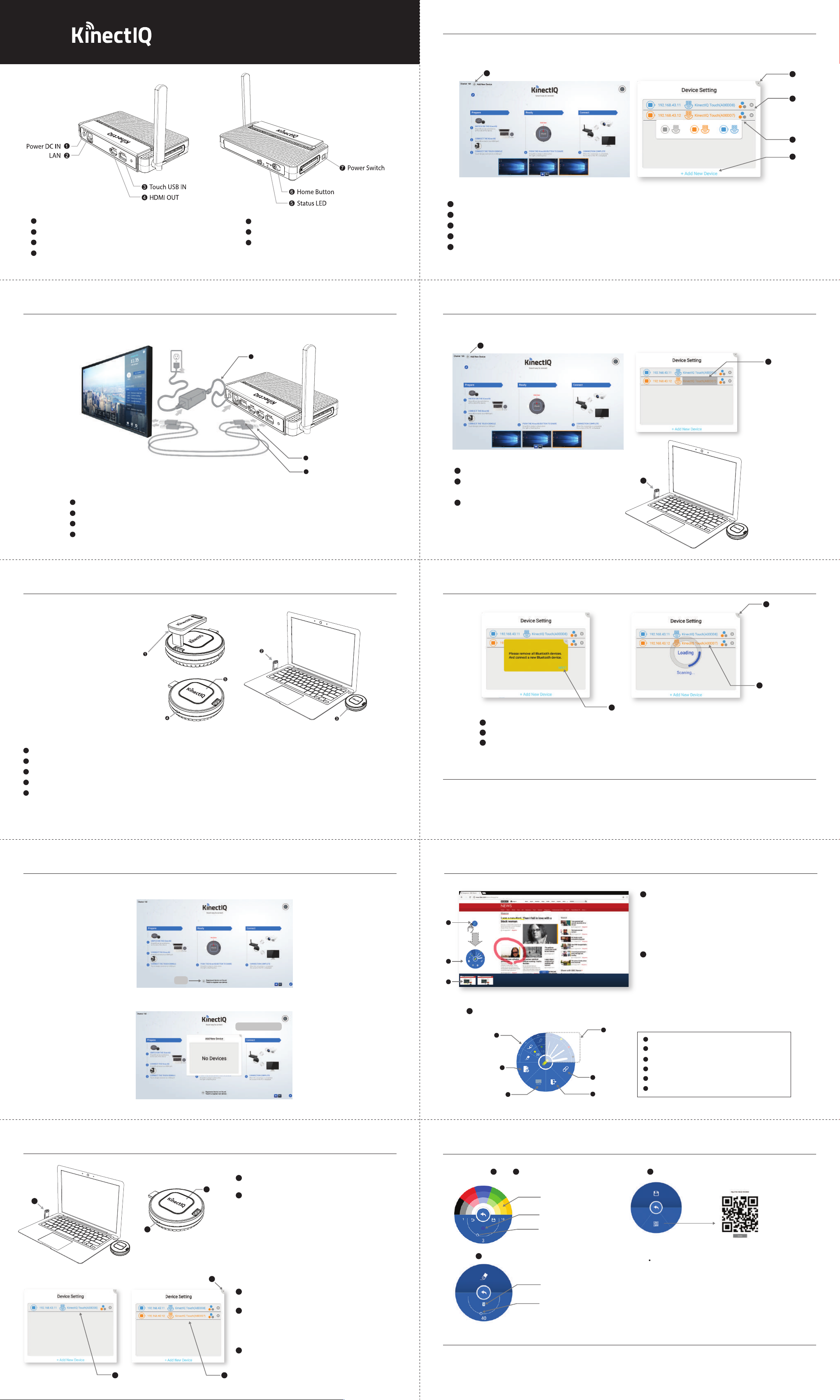
Pairing Receiver and Transmitters
2. Add/Remove Paired Transmitters
1
Power DC : Insert Power Supply
2
LAN Port : Connect Ethernet cable
3
HDMI OUT : Connect to display device
4
Touch USB IN Port : Connect to a touch display
Installation
5
Status LED
6
Home button : Return to Home screen
7
Power Switch : Turn Receiver ON/OFF
1
1
Click on the Add New Device Button to enter Set Mode
2
Click on Add New Device at the bottom of the Set Mode Check window to pair additional KinectIQ PRO Transmitters.
3
Set Transmitter Color.
4
To remove a Transmitter that has already been paired, click on the X button to the right of the paired Transmitter.
5
When all Transmitters have been paired, click on the X button at the top right corner of the Set Mode Check window to exit the setup procedure
Pairing Receiver and Transmitters
5
4
3
2
Step 1. Install Receiver
1
Connect HDMI cable from touch display to the HDMI OUT port of the KinectIQ PRO Receiver.
2
Connect USB cable from touch display to the Touch IN USB port of the Receiver.
3
Connect the Power Supply provided to the Power In port of the Receiver.
4
Turn Power Switch On.
3
Power adapter
2
1
USB
HDMI
3. Pair additional USB dongle
1
1
Click on the Add New Device Button to enter Set Mode.
2
Click on the Mac address of the Touch USB dongle to re-register
within the Set Mode Check window.
3
Connect the Touch USB dongle in a laptop to start pairing.
(Only one USB dongle shall be connected to laptop
for new registration)
2
3
Installation
Step 2. Install Transmitter
1
Remove Touch USB Dongle from KinectIQ PRO Transmitter.
2
Insert Touch USB Dongle into the USB IN port of your laptop or PC.
3
Plug KinectIQ PRO Transmitter in to the HDMI out port of laptop or PC. Use the HDMI extension cable provided if needed.
4
Slide the power switch to the left to turn power ON and the Status LED will light blue.
5
Click Transmit button and an image will appear on the display device of which the Receiver is installed.
• If multiple Transmitters are connected, the corresponding screen of the Transmitter that has just been clicked will appear, as part of
the product’s integrated switching function.
Pairing Receiver and Transmitters
4
4
Click NEXT on the lower right corner of the yellow pop-up window.
5
Check the Mac address of newly registered Touch USB dongle.
6
Click on the X button at top right corner of the Set Mode Check window to exit the setup procedure.
Notice
The distance available for wireless application may vary depending on the user environment.
The wireless device in use may be subjected to radio interference during operation.
The screen in part may not show if the aspect ratio of image being replayed does not match with that of the monitor.
Turn power OFF of the product and of the Transmitter when not in use.
6
5
Pairing Receiver and Transmitters
1. Initial pairing
PAIR
Pair the transmitter with the Receiver by entering Set Mode in the Settings.
Ready for PAIRING
Overlay Annotation
1
3
2
3
Overlay Annotation Tool
- Tool Layout
1
3
4
1
While mirroring, click on the overlay annotation icon to
take notes and draw on your display screen. This feature
allows for full interactivity of your presentation.
- Overlay annotation is feasible on word les, image les,
internet browser les, etc
2
Overlay annotation thumbnail
- Save overlay annotations as pdf le
- Click on overlay annotation thumbnail to view on
screen
2
1
Basic tools : pen, highlighter, eraser
2
Set line thickness
3
Add new page : save current page and add a new page
4
5
6
White board
5
Share : save/share les via email, QR Code, Cloud
6
Exit
Pairing Receiver and Transmitters
1
2
Overlay Annotation
1
1 2
- Share : Share via E-mail, QR-code Scan, Cloud
Choose color
Current color
Width
Erase entire screen
Select width
1
Connect the Touch USB dongle to the USB port of
2
laptop or PC.
2
Press and hold the Transmit Button while switching the
power switch to ON. Keep holding the Transmit Button
for ~10 seconds until status LED starts ashing blue.
- Pen Setting : Click Select pen color, width
- Eraser : Click
5
3
When paired, the IP address will appear on the Set Mode
Check window.
4
For additional Transmitters, repeat above procedure.
- Remove the USB Dongle from laptop upon setup.
- Upon each new Transmitter paired, please check that a new
IP address is added on the Set Mode Check window.
5
Click on the X button at the top right corner of the Set Mode
Check window to exit the setup procedure.
43
Notice
The distance available for wireless application may vary depending on the user environment.
The wireless device in use may be subjected to radio interference during operation.
The screen in part may not show if the aspect ratio of image being replayed does not match with that of the monitor.
Turn power OFF of the product and of the Transmitter when not in use.
5
1) QR Code : Smart device QR Code reader
Smart device, KinectIQ Receiver must be connected to same
Wi- network
RF spec.
- AT-E1000P or AT-E1000P : 5180 – 5220 MHz, 5745 – 5825 MHz
Hardware version
- AT-E1000P or AT-E1000P : 0.7
Software version
- AT-E1000P or AT-E1000P : 1.1.6
Operating Temperature
- AT-E1000P or AT-E1000P : 0-40 Degree C
Power supply
- AT-E1000P or AT-E1000P : 5.0 Vd.c.
- This device complies with Industry Canada license-exempt RSS standard(s).
Operation is subject to the following two conditions:
(1) this device may not cause interference, and
(2) this device must accept any interference, including interference that may cause undesired
operation of the device.
- Le present appareil est conforme aux CNR d'Industrie Canada applicables aux appareils radio
exempts de licence. L'exploitation est autorisee aux deux conditions suivantes :
(1) l'appareil ne doit pas produire de brouillage, et.
(2) l'utilisateur de l'appareil doit accepter tout brouillage radio electrique subi, meme si le
brouillage est susceptible d'en compromettre le fonctionnement.
- This equipment should be installed and operated with minimum 20 cm between the radiator
and your body.
- Cet appareil doit être installé et utilisé avec un minimum de 20 cm entre le radiateur et votre
corps.
- This device is restricted to indoor use only within the 5.15 ~ 5.25GHz Band.
- Cet appareil est restreint à l'utilisation à l'intérieur seulement dans la bande 5.15 ~ 5.25GHz.
2402 – 2480 MHz
FCC Caution
Class B Digital Device
Note : This equipment has been tested and found to comply with the limits for a Class
B digital device, pursuant to part 15 of the FCC Rules. These limits are designed to
provide reasonable protection against harmful interference in a residential installation
This equipment generates, uses and can radiate radio frequency energy and, if not
installed and used in accordance with the instructions, may cause harmful
interference to radio communications, However, there is no guarantee that interference
will not occur in a particular installation. If this equipment does cause harmful
interference to radio or television reception, which can be determined by turning the
equipment off and on, the user is encouraged to try to correct the interference by one
or more of the following measures:
- Reorient or relocate the receiving antenna.
- Increase the separation between the equipment and receiver.
- Connect the equipment into an outlet on a circuit different from that to which the
receiver is connected.
- Consult the dealer or an experienced radio/TV technician for help.
Any changes or modifications in construction of this device which are not expressly
approved by the party responsible for compliance could void the user's authority to
operate the equipment.
Part 15C
This device complies with part 15 of the FCC Rules. Operation is subject to the
following two conditions: (1) This device may not cause harmful interference, and (2)
this device must accept any interference received. Including interference that may
cause undesired operation.
 Loading...