

Motovario TBP Series, TP Series, TSX Series, THX Series, TPX Series Use And Maintenance Instructions
...
www.motovario.com
USE AND MAINTENANCE
INSTRUCTIONS FOR
ELECTRIC MOTORS
EN
QL0219 / REV.3

ORIGINAL VERSION IN ITALIAN
TRANSLATED VERSION IN ENGLISH

Chapter
1 Scope 4
2 General safety warning 4
3 Compliance with EU directives – CE marking 4
4 Electric motor identication 5
5 Mechanical installation 7
6 Electrical installation and start-up 8
7 Incremental encoder 9
8 Forced ventilation 10
9 Electric motor protection 11
USE AND MAINTENANCE MANUAL FOR ELECTRIC MOTORS
CONTENTS
10 Maintenance / spare parts 12
11 Assembly/disassembly instructions 12
12 Disposal and recycling 12
13 Storage 13
14
15
16
17
18 "ML type" direct current brake 18
19 Motor power supply wiring diagrams 20
Warranty claims
Assistance
"FM type" direct current brake
"MS type" alternating current brake
13
13
14
16
33

www.motovario.com
1. SCOPE
The instructions in this manual apply to the following series of asynchronous electric motors produced by MOTOVARIO S.p.A:
The instructions in this manual apply to the following series of asynchronous electric motors produced by MOTOVARIO S.p.A:
- TS (three-phase, single polarity, standard eciency);
- TH (three-phase, single polarity, high eciency);
- TP (three-phase, single polarity, premium eciency);
- TBS (three-phase, self-braking, single polarity, standard eciency);
- TBH (three-phase, self-braking, single polarity, high eciency);
- TBP (three-phase, self-braking, single polarity, premium eciency);
- TSX (three-phase, single polarity, standard eciency for aggressive / corrosive / food environments);
- THX (three-phase, single polarity, high eciency for aggressive / corrosive / food environments);
- TPX (three-phase, single polarity, premium eciency for aggressive / corrosive / food environments);
- TBSX (three-phase, self-braking, single polarity, standard eciency for aggressive / corrosive / food environments);
- TBHX (three-phase, self-braking, single polarity, high eciency for aggressive / corrosive / food environments);
- TBPX (three-phase, self-braking, single polarity, premium eciency for aggressive / corrosive / food environments);
- D (three-phase, double polarity);
- DB (three-phase, self-braking, double polarity);
- S (single-phase);
- HSE (high starting torque single-phase with electronic cutout).
Specialist products (i.e. dierent to those present in our catalogues and/or product oers) or specialist applications (e.g. power supply
from inverters) require additional information to be provided.
2. GENERAL SAFETY WARNING
Electric motors are a source of electrical hazards and consequently their improper use may cause injury and/or damage to people,
animals and objects.
Read the following instructions carefully before starting up the motor; all installation, commissioning, maintenance and
protection of the electric motor must be done by qualified staff in full compliance with established legislation and technical
regulations as well as the safety regulations governing the electrical equipment of machinery as declared by European
standard EN60204-1.
Please note that the present literature supplements and does not replace any established legislation, technical regulations or
safety regulations governing electric motors; it merely makes practical suggestions that qualified personnel can make use of.
It is forbidden to use electric motors in potentially explosive atmospheres unless expressly foreseen and specified on the
nameplate in compliance with European Directive 94/9/EC.
Motovario is exempt from any responsibility deriving from improper use or failure to follow current safety directives governing
electric material.
3. COMPLIANCE WITH EU DIRECTIVES – CE MARKING
Standard three-phase asynchronous electric motors (TS, TH, TP, TSX, THX, TPX, D series) and single-phase (S and HSE series) comply with
the standardised construction regulation IEC 60034-1 and therefore meet the requirements of the Low Voltage Directive 2014/35/EU.
The electric motor, considered as a component, is compliant with the following directives:
• Directive ROHS 2011/65/EU relating to the prohibition or the limitation of the use of noxious substances in electrical and electronic
equipment.
• Directive ErP 2009/125/EC on ecological designing of energy-using devices and in particular EC Regulation
no. 640/2009 (and subsequent UE modication no. 4/2014) on the ecological design of electric motors.
• Directive EMC 2014/30/EU relating to intrinsic characteristics in relation to emissions and levels of immunity.
All standard mounting position motors in continuous operation and powered from the mains are compliant with general standards
EN 61000-6-2, EN 61000-6-3, 61000-6-4 on electromagnetic emission and immunity; in the case of brake motors (TBS, TBH, TBP, TBSX,
TBHX, TBPX, DB RRSD series) or full wave rectier (DBR) the lter is implemented by connecting a 440Vac 0.22μF class X2 condenser in
parallel to the AC power, as per EN132400; the half-wave rectier type RV6 has no integral lter and is thus suited to installation with
the lter upline of the machine (to be done by the client). Follow the instructions of the devices' manufacturers in case of intermittent
malfunctions and interferences generated by the triggering devices, power supplies with inverters, systems with encoders, etc. All
electric motors are intended to be integrated in equipment and complete systems and must never be started until the equipment
they are installed in is compliant with Machinery Directive (Certicate of Integration - Directive 2006/42/EC Ann. II B). The compliance
of a complete installation with the "Machinery Directive" and the EMC Directive is the responsibility of the machine's manufacturer.
According to EC Regulation no. 640/2009, starting from 01/01/2015 the motors of the TH series (IE2, high eciency) with power greater
than or equal to 7.5 kW can be started in the European Union only if supplied by an inverter. From 01/01/2017 this provision applies to
the motors of the TH series with power greater than or equal to 0.75 kW.
4
USE AND MAINTENANCE MANUAL FOR ELECTRIC MOTORS
4. ELECTRIC MOTOR IDENTIFICATION
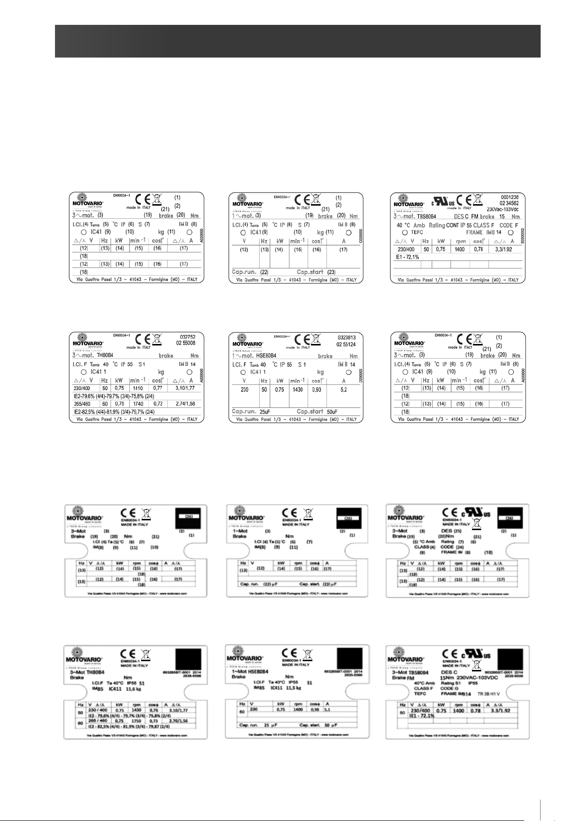
The electric motor is equipped with a metal silk-screen printed and/or punched nameplate or an adhesive label glued on metal support.
Symbols and abbreviations are detailed in the following page.
NAMEPLATES
THREEPHASE MOTOR
NAMEPLATE LAYOUT
THREE-PHASE MOTOR
COMPLETED EXAMPLE
SINGLEPHASE MOTOR
NAMEPLATE LAYOUT
SINGLE-PHASE MOTOR
COMPLETED EXAMPLE
UL/CSA MOTOR NAMEPLATE
LAYOUT
UL/CSA MOTOR
COMPLETED EXAMPLE
LABELS
THREEPHASE MOTOR LABEL SINGLEPHASE MOTOR LABEL UL/CSA MOTOR LABEL
5

www.motovario.com
(1) Serial number
(2) Year of manufacture – order number
(3) Motor type code
(series/size/no. poles)
(4) Insulation class
(5) Maximum ambient operating temperature
(6) IP protection rating
(7) Service
(8) Construction type
(9) Cooling method (*)
(10) Additional options (see below)
(11) Motor weight (only for > 30 kg)
(12) Motor voltage (depending on connection)
(13) Power frequency [Hz]
(14) Nominal power delivery [kW]
(15) Nominal speed [rpm]
(16) Nominal power factor
(17) Nominal current (depending on connection) [A]
(18) Code IE1, IE2 or IE3 (depending on type of motor and
whether applicable) followed by eciency value at 4/4, 3/4 and
2/4 of nominal power.
(brake motors only)
(19) Brake type
(20) Nominal braking moment [Nm]
(*) For UL/CSA motors, the cooling system is indicated with the following codes:
TEFC = (T)otally (E)nclosed (F)an (C)ooled - corresponds to IC411 (self-ventilation)
TENV = (T)otally (E)nclosed (N)ot (V)entilated - corresponds to IC410 (non-ventilated)
TEBC = (T)otally (E)nclosed (B)lower (C)ooled - corresponds to IC416 (forced ventilation)
(21) Brake power supply
(single-phase version only)
(22) running capacitor [μF]
(23) starting capacitor [μF]
(UL/CSA version only)
(24) “NEMA Electrical Design Classication”
(25) locked rotor current identication code
(ANSI/NFPA 70-1996)
(26) QR code
Additional options (10) notes
- H1 condensation heaters for voltage 110V
- H2 condensation heaters for voltage 230V
- TR humid environment construction
- LT low temperature construction
- HT high temperature construction
- 3B no. 3 bimetal thermal fuses
- 3P no. 3 thermistors (PTC)
- A backstop device (anti-clockwise rotation permitted)
- B backstop device (clockwise rotation permitted)
- E encoder
- V ywheel
- HC rapid connection
6

USE AND MAINTENANCE MANUAL FOR ELECTRIC MOTORS
5. MECHANICAL INSTALLATION
Before installation please check that:
1) the electric motor is not visibly damaged (whether damaged in transit or during storage).
2) the information on the nameplate corresponds with the features of the electric motor and its intended use; the power supply voltage
matches the mains voltage; the permitted voltage tolerance is ±10% for 230/400V 50Hz and 265/460V 60Hz, and ±5% for other voltages
and/or single-phase motors.
3) the ambient temperature is between -15°C and +40°C (+50°C 2- and 4-pole TS motors with nominal power >= 0.75 kW); in addition,
the altitude must be < 1000m above sea level; ambient temperatures outside this range and/or higher altitudes require the application
of a corrective power factor (see product catalogue).
4) If the environment features sudden temperature changes with possible consequent condensate formation, it is recommended to
request the condensation heaters and/or the condensate discharge holes.
5) The IP protection rating given on the nameplate is suited to the environment under the terms of IEC 60034-5.
6) In outdoor installations, protect the motor from the direct sunlight and, if possible, from the atmospheric agents.
Use the provided attachment points to lift the motor; the eyebolts on the motor are for lifting the motor only and not any other
equipment coupled to it; ensure that the systems mounted to the motor match the electric motor's specications.
Preliminary tasks:
1) remove any fastenings and protective material used for shipping (e.g. guards on the ends of the motor shaft) and check that the shaft
turns freely (for TBS – TBH – TBP – TBSX - TBHX - TBPX – DB series brake motors, rst release the manual release lever if present);
2) carefully clean the ends of the shaft with a normal solvent to remove any rust protection, contaminants and similar matter; take care
that the solvent does not get into the bearings or comes into contact with the seal ring lips and damages them;
3) check, especially after lengthy storage, that the motor has not absorbed humidity, by measuring the insulation resistance which must
be < 10MΩ at 20°C; take the measurement by applying a direct current of 500V between the phases towards GND; the windings must
be discharged immediately after the measurement has been taken. If the insulation resistance is insucient the motor must be dried
with hot air or using an isolation transformer, connecting the windings of each phase in series and applying an auxiliary AC current of
10-20% of the nominal current, until the resistance measurement is satisfactory.
Installing the motor:
1) take care to secure the motor adequately in relation to its weight, mounting type and position;
2) assemble the motor on a at, rigid, vibration-free and deformation-resistant surface; align the motor carefully with the driven
machine to avoid inadmissible stresses on the shaft and observe the overhung and axial loading specications (see product catalogue);
misalignments and forced locking can result in hazardous overheating;
3) if the motor construction type is IEC B14, the four retaining screws must be screwed in the ange even if they are not necessary. It
is recommendable to apply sealant, such as Loctite 242, on the retaining screws thread. The maximum screwing depth in the bearing
shield is 2 x d, where "d" is the threaded hole;
4) vertical installations must include measures to prevent foreign bodies falling into the ventilation slots; in such case, we recommend
using a fan cover with awning (compulsory in case of self-braking motor);
5) during assembly, avoid damaging the bearings by using the shaft as a stop after removing the fan cover; do not knock the end of
the shaft;
6) the motor shaft is dynamically balanced and complete with half key from size 90 upwards, with normal vibration; make sure that any
parts to be locked to the motor shaft are balanced with half key; if using double-ended shaft motors, take care not to start the motor
until the unused key has been secured.
7) the motor must be mounted in such a way that the nameplate data is legible, the terminal block box can be inspected, the motor
compartment can be cleaned, there are no moving parts outside the guards (e.g. fan cover), the assembly is suciently ventilated
without bottlenecks or machining residue, dust or uids in the air supply, and that nothing is blocking normal dispersal of heat; nally,
ensure that there is sucient distance between the fan cover holes and any external protective devices which could potentially block
the inow of cooling air.
8) in particularly humid conditions: make sure, if possible, that the cables enter the terminal block box from below, and check for
condensation; if there is a condensation drain hole, drain the condensation, then ret the plug to restore the box's IP rating. Do this only
with the power supply visibly shut o (breaker open). If there are anti-condensation heaters, make sure the motor is not powered up or
rotating before turning them on; also make sure the heaters' power supply is compliant with their ratings.
7

www.motovario.com
6. ELECTRICAL INSTALLATION AND START UP
1) Connect the motor to the mains as shown in the diagram inside the terminal block box (the wiring diagrams are also included at the
end of this manual).
2) Do not connect up or start the motor if the wiring diagram is absent.
3) Do not start the motor with the key unengaged.
4) Before making the connections, check that the motor's wires are properly tightened down to the terminal block; to connect the cable,
use the parts kit in the bag supplied with the motor, paying particular attention to the maximum tightening torques; the terminals used
to hook up the cable must be isolated to ensure the minimum distances between the live parts and inactive metal parts; the cable gland
must be suited to the external diameter of the cable used; all unused cable entry points must be sealed to restore the box's IP rating.
5) As well as the main power terminals, the terminal block box may also contain the cable terminals for the thermal protective devices
and/or condensation heaters and/or the brake (if the motor in question is a brake motor with separate power supply). The cable
terminals in the terminal block for thermal protective devices and condensation heaters are usually free. For connecting up brakes with
separate power supplies please refer to the relevant section.
Motors can also be tted with incremental encoders and/or an external forced ventilation capacity (servo-ventilation). Please consult
the relevant sections.
6) The power and GND cables must comply with established practice and standards, and be properly insulated and rated for the current
draw; the connection cabling and cable cross sections must comply with EN60204-1.
7) All motors are equipped for grounding inside the terminal block box and outside on the motor casing; the GND clamp points are
marked with the relevant symbol.
8) Secure the GND cable to prevent its slackening (use an elastic washer between the terminal and the bolt) and rotating (use only split
cable terminals).
9) Before starting up the motor, check its direction of rotation; if it is required to run in the opposite direction from the default direction,
for three-phase motors (series TS, TH, TP, TSX, THX, TPX, TBS, TBH, TBP, TBSX, TBHX, TBPX, D; DB) simply swap 2 phases; for single-phase
motors (series S), refer to the wiring diagram. The direction of rotation is clockwise when seen from the drive side.
10) If a backstop device is present, do not start the motor in the stop direction; for inspection reasons, the backstop can only be
operated once in the stop direction at a voltage less than half the power voltage.
11) After wiring the unit, ret the terminal block cover with its gasket.
12) For brake motors, check the operation of the brake and its braking torque before starting the motor.
13) For motors of the TSX, THX, TPX, TBSX, TBHX, TBPX series, smear sealant (like LOCTITE 5331) on the cable glands and the closing
plugs and tighten them correctly; properly seal the cable inlet; thoroughly clean the sealing surface of the terminal block box; in case
of installation in particularly aggressive environments, seals (to be replaced if damaged) must be stuck on the terminal block box cover
with suitable sealant (like LOCTITE 3020); if present and if necessary, touch-up the anti-corrosion pain with kit that can be supplied
upon request.
14) Do not touch the motor's housing while it is running as it can reach more than 50°C.
8
 Loading...