

Motovario AM16-4001-SH3F, AM16-4003-SH3F, AM16-4002-SH3F, AM16-4008-SH3F, AM16-4010-SH3F Series Manual
...
TABLE OF CONTENTS
CHAPTER 1 SAFETY PRECAUTIONS ............................................................................................................ 1
EFORE SUPPLYING POWER TO THE INVERTER
1.1 B
1.2 W
1.3 B
1.4 P
1.5 O
1.6 M
1.7 D
CHAPTER 2 MODEL DESCRIPTION ............................................................................................................... 6
2.1 N
NVERTER MODELS – MOTOR POWER RATING
2.2 I
CHAPTER 3 ENVIRONMENT AND INSTALLATION ...................................................................................... 9
3.1 W
3.2 W
3.3 G
..................................................................................................................................................... 2
IRING
EFORE OPERATION
ARAMETERS SETTING
PERATION
AINTENANCE, INSPECTION AND REPLACEMENT
ISPOSAL OF THE INVERTER
AMEPLATE DATA
IRE GAUGES AND TIGHTENING TORQUE
IRING PERIPHERAL POWER DEVICES
ENERAL WIRING DIAGRAM
.............................................................................................................................................. 4
................................................................................................................................. 3
.............................................................................................................................. 3
...................................................................................................................... 5
.................................................................................................................................... 6
.................................................................................................... 10
.................................................................................................................... 12
.......................................................................................... 1
........................................................................................ 5
(HD – H
.................................................................................................. 9
EAVY DUTY
) ............................................................. 8
3.4 I
NPUT / OUTPUT POWER SECTION BLOCK DIAGRAM
3.4.1 Cooling Fan Supply Voltage Selection (400V class) ................. Hiba! A könyvjelző nem létezik.
3.5 U
SER TERMINALS (CONTROL CIRCUIT TERMINALS
OWER TERMINALS
3.6 P
3.7 I
NVERTER SPECIFICATIONS
3.8 I
NVERTER DIMENSIONS
CHAPTER 4 KEYPAD AND PROGRAMMING FUNCTIONS ........................................................................ 31
4.1 LED K
4.1.1 Keypad Display and Keys .......................................................................................................... 31
4.2 P
CHAPTER 5 TROUBLESHOOTING AND FAULT DIAGNOSTICS ............................................................... 97
5.1 G
5.2 F
5.3 W
5.4 A
EYPAD
ARAMETERS
ENERAL
AULT DETECTION FUNCTION
ARNING / SELF-DIAGNOSIS DETECTION FUNCTION
UTO-TUNING ERROR
............................................................................................................................................... 97
................................................................................................................................. 18
...................................................................................................................... 21
............................................................................................................................ 26
......................................................................................................................................... 31
......................................................................................................................................... 33
.................................................................................................................. 97
........................................................................................................................... 113
................................................................................. 13
) .................................................................................. 15
............................................................................... 103
5.5 PM
MOTOR AUTO-TUNING ERROR
......................................................................................................... 114

Chapter 1 Safety Precautions
1.1 Before Supplying Power to the Inverter
Warning
The main circuit must be correctly wired. For single phase supply use input
terminals (R/L1, T/L3) and for three phase supply use input terminals (R/L1, S/L2,
T/L3). Terminals U/T1, V/T2, W/T3 must only be used to connect the motor.
Connecting the input supply to any of the U/T1, V/T2 or W/T3 terminals will cause
damage to the inverter.
Caution
To avoid the front cover from disengaging or other physical damage, do not
carry the inverter by its cover. Support the unit by its heat sink when
transporting. Improper handling can damage the inverter or injure personnel,
and should be avoided.
To avoid the risk of fire, do not install the inverter on or near flammable objects.
Install on nonflammable objects such as metal surfaces.
If several inverters are placed inside the same control panel, provide adequate
ventilation to maintain the temperature below 40°C/104°F (50°C/122°F without a
dust cover) to avoid overheating or fire.
When removing or installing the digital operator, turn off the power first, and then
follow the instructions in this manual to avoid operator error or loss of display
caused by faulty connections.
Warning
This product is sold subject to IEC 61800-3. In a domestic environment this product
may cause radio interference in which case the user may need to apply corrective
measures.
Motor over temperature protection is provided.
1

1.2 Wiring
Warning
Always turn OFF the power supply before attempting inverter installation and
wiring of the user terminals.
Wiring must be performed by a qualified personnel / certified electrician.
Make sure the inverter is properly grounded. (200V Class: Grounding
impedance shall be less than 100Ω. 400V Class: Grounding impedance shall be
less than 10Ω.)
Make sure the inverter is properly grounded. It is required to disconnect the
ground wire in the control board to avoid the sudden surge causing damage on
electronic parts if it is improperly grounded.
RCD is required to be in compliance with the protection norm of B-type leakage
current.
Please check and test emergency stop circuits after wiring. (Installer is
responsible for the correct wiring.)
Never touch any of the input or output power lines directly or allow any input of
output power lines to come in contact with the inverter case.
Do not perform a dielectric voltage withstand test (megger) on the inverter this will
result in inverter damage to the semiconductor components.
Caution
The line voltage applied must comply with the inverter’s specified input voltage.
(See product nameplate section 2.1)
Connect braking resistor and braking unit to the designated terminals. (See
section 3.10)
Do not connect a braking resistor directly to the DC terminals P (+) and N (-), otherwise fire
may result.
Use wire gauge recommendations and torque specifications. (See Wire Gauge and
Torque Specification in section 3.6)
Never connect input power to the inverter output terminals U/T1, V/T2, W/T3.
Do not connect a contactor or switch in series with the inverter and the motor.
Do not connect a power factor correction capacitor or surge suppressor to the
inverter output.
Ensure the interference generated by the inverter and motor does not affect
peripheral devices.
2
1.3 Before Operation
Warning
Make sure the inverter capacity matches the parameters 13-00.
Reduce the carrier frequency (parameter 11-01) If the cable from the inverter to
the motor is greater than 80 ft (25m). A high-frequency current can be generated
by stray capacitance between the cables and result in an overcurrent trip of the
inverter, an increase in leakage current, or an inaccurate current readout.
Be sure to install all covers before turning on power. Do not remove any of the
covers while power to the inverter is on, otherwise electric shock may occur.
Do not operate switches with wet hands, otherwise electric shock may result.
Do not touch inverter terminals when energized even if inverter has stopped,
otherwise electric shock may result.
1.4 Parameters Setting
Caution
Do not connect a load to the motor while performing a rotational auto-tune.
Make sure the motor can freely run and there is sufficient space around the
motor when performing a rotational auto-tune.
3
1.5 Operation
Warning
Be sure to install all covers before turning on power. Do not remove any of the
covers while power to the inverter is on, otherwise electric shock may occur.
Do not connect or disconnect the motor during operation. This will cause the
inverter to trip and may cause damage to the inverter.
Operations may start suddenly if an alarm or fault is reset with a run command
active. Confirm that no run command is active upon resetting the alarm or fault,
otherwise accidents may occur.
Do not operate switches with wet hands, otherwise electric shock may result.
It provides an independent external hardware emergency switch, which emergently
shuts down the inverter output in the case of danger.
If automatic restart after power recovery (parameter 07-00) is enabled, the inverter
will start automatically after power is restored.
Make sure it is safe to operate the inverter and motor before performing a rotational
auto-tune.
Do not touch inverter terminals when energized even if inverter has stopped,
otherwise electric shock may result.
Do not check signals on circuit boards while the inverter is running.
After the power is turned off, the cooling fan may continue to run for some time.
Caution
Do not touch heat-generating components such as heat sinks and braking
resistors.
Carefully check the performance of motor or machine before operating at high
speed, otherwise Injury may result.
Note the parameter settings related to the braking unit when applicable.
Do not use the inverter braking function for mechanical holding, otherwise injury
may result.
Do not check signals on circuit boards while the inverter is running.
4
1.6 Maintenance, Inspection and Replacement
Warning
Wait a minimum of five minutes after power has been turned OFF before starting an
inspection. Also confirm that the charge light is OFF and that the DC bus voltage
has dropped below 25Vdc.
Never touch high voltage terminals in the inverter.
Make sure power to the inverter is disconnected before disassembling the inverter.
Only authorized personnel should perform maintenance, inspection, and
replacement operations. (Take off metal jewelry such as watches and rings and use
insulated tools.)
Caution
The Inverter can be used in an environment with a temperature range from 14°
~104(140) °F (-10~+40(60)°C) and relative humidity of 95% non-condensing.
The inverter must be operated in a dust, gas, mist and moisture free
environment.
1.7 Disposal of the Inverter
Caution
Please dispose of this unit with care as an industrial waste and according to your
required local regulations.
The capacitors of inverter main circuit and printed circuit board are considered
as hazardous waste and must not be burned.
The Plastic enclosure and parts of the inverter such as the top cover board will
release harmful gases if burned.
5
Chapter 2 Model Description
(P/N Bar code)
(S/N Bar code)
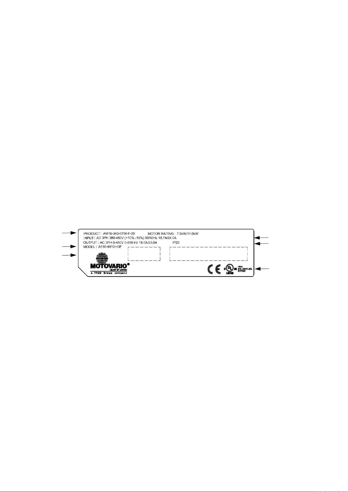
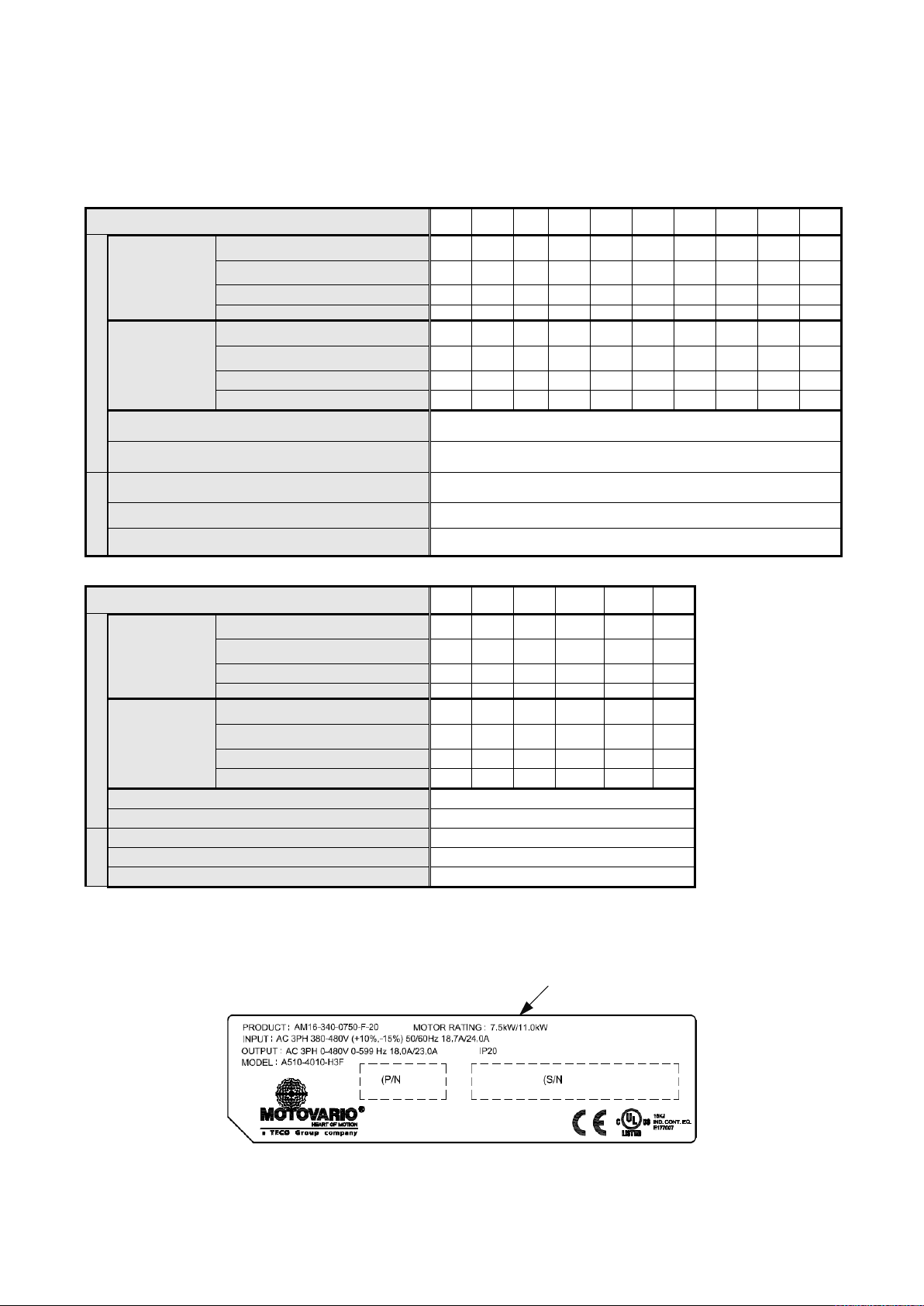
2.1 Nameplate Data
It is essential to verify the AM16 inverter nameplate and make sure that the AM16 inverter has the
correct rating so it can be used in your application with the proper sized AC motor.
Unpack the AM16 inverter and check the following:
(1) The AM16 inverter and start-up and installation manual are contained in the package.
(2) The AM16 inverter has not been damaged during transportation there should be no dents or
parts missing.
(3) The AM16 inverter is the type you ordered. You can check the type and specifications on the
main nameplate.
(4) Check that the input voltage range meets the input power requirements.
(5) Ensure that the motor kW matches the motor rating of the inverter.
HD: Heavy Duty (Constant Torque); ND: Normal Duty (Variable Torque) (1HP = 0.746 kW)
Product Name
& Motor Rating
Series No
Code No
Input Power Specifications
Output Power Specifications
UL and CE Marks
6

Model Identification:
20 = IP20 enclosure
AM16-340-0075-F-20
Series Power supply Motor power EMI Filter IP degree
AM16
340 0075 (blanck) 20
0150 F
0220
340 = 3ph 400V
0400
0550
0750
1100
1500
0075 = 0.75 kW
1850
0150 = 1.5 kW
(blank) = No EMI filter inside (only
from Motor-power = 5500)
F = integrated EMI filter A-class, C2-
category (only up to
Motor-power = 4500)
2200
0220 = 2.2 kW
3000
0400 = 4 kW
3700
0550 = 5.5 kW
4500
0750 = 7.5 kW
5500
1100 = 11 kW
7500
1500 = 15 kW
9000
1850 = 18.5 kW
2200 = 22 kW
3000 = 30 kW
3700 = 37 kW
4500 = 45 kW
5500 = 55 kW
7500 = 75 kW
9000 = 90 kW
7

2.2 Inverter Models – Motor Power Rating
Applied
HD – Heavy Duty: 150% OverLoad
Voltage AM16 Model
AM16-4001-SH3F
AM16-4002-SH3F
AM16-4003-SH3F
AM16-4005-SH3F
AM16-4008-SH3F
AM16-4010-SH3F
3ph, 380~480V
+10%/-15%
50/60Hz
Short Circuit Rating: 400V Class: 5kA
AM16-4015-SH3F
AM16-4020-SH3F
AM16-4025-SH3F
AM16-4030-SH3F
AM16-4040-SH3F
AM16-4050-SH3F
AM16-4060-SH3F
AM16-4075-SH3
AM16-4100-SH3
AM16-4125-SH3
Motor
(KW)
0.75
1.5
2.2
3.7
5.5
7.5
11 ◎
15
18.5
22
30 ◎
37
45
55
75
94
Internal Filter
with without
◎
◎
◎
◎
◎
◎
◎
◎
◎
◎
◎
◎
◎
◎
Note: The spec. please refer to Chapter 3.7, the rated current is 330/370A.
8

Chapter 3 Environment and Installation
Terminal
Model of the
Model of
3.1 Wire Gauges and Tightening Torque
To comply with UL standards, use UL approved copper wires (rated 75° C) and round
crimp terminals (UL Listed products) as shown in table below when connecting to the main
circuit terminals. MOTOVARIO recommends using crimp terminals manufactured by
NICHIFU Terminal Industry Co., Ltd and the terminal crimping tool recommended by the
manufacturer for crimping terminals and the insulating sleeve.
Wire size
mm2 (AWG)
0.75 (18)
1.25 (16)
2 (14)
3.5 / 5.5
(12/10)
8 (8)
14 (6)
22 (4)
30 / 38 (3 /2)
50 / 60
(1/1/0)
70 (2/0)
80 (3/0)
100 (4/0)
screw
size
M3.5 R1.25-3.5 8.2 to 10 (7.1 to 8.7) TIC 1.25 NH 1
M4 R1.25-4 12.2 to 14 (10.4 to 12.1) TIC 1.25 NH 1
M3.5 R1.25-3.5 8.2 to 10 (7.1 to 8.7) TIC 1.25 NH 1
M4 R1.25-4 12.2 to 14 (10.4 to 12.1) TIC 1.25 NH 1
M3.5 R2-3.5 8.2 to 10 (7.1 to 8.7) TIC 2 NH 1 / 9
M4 R2-4 12.2 to 14 (10.4 to 12.1) TIC 2 NH 1 / 9
M5 R2-5 22.1 to 24 (17.7 to 20.8) TIC 2 NH 1 / 9
M6 R2-6 25.5 to 30.0 (22.1 to 26.0) TIC 2 NH 1 / 9
M4 R5.5-4 12.2 to 14 (10.4 to 12.1) TIC 5.5 NH 1 / 9
M5 R5.5-5 20.4 to 24 (17.7 to 20.8) TIC 5.5 NH 1 / 9
M6 R5.5-6 25.5 to 30.0 (22.1 to 26.0) TIC 5.5 NH 1 / 9
M8 R5.5-8 61.2 to 66.0 (53.0 to 57.2) TIC 5.5 NH 1 / 9
M4 R8-4 12.2 to 14 (10.4 to 12.1) TIC 8 NOP 60
M5 R8-5 20.4 to 24 (17.7 to 20.8) TIC 8 NOP 60
M6 R8-6 25.5 to 30.0 (22.1 to 26.0) TIC 8 NOP 60
M8 R8-8 61.2 to 66.0 (53.0 to 57.2) TIC 8 NOP 60
M4 R14-4 12.2 to 14 (10.4 to 12.1) TIC 14 NH 1 / 9
M5 R14-5 20.4 to 24 (17.7 to 20.8) TIC 14 NH 1 / 9
M6 R14-6 25.5 to 30.0 (22.1 to 26.0) TIC 14 NH 1 / 9
M8 R14-8 61.2 to 66.0 (53.0 to 57.2) TIC 14 NH 1 / 9
M6 R22-6 25.5 to 30.0 (22.1 to 26.0) TIC 22 NOP 60/ 150H
M8 R22-8 61.2 to 66.0 (53.0 to 57.2) TIC 22 NOP 60/ 150H
M6 R38-6 25.5 to 30.0 (22.1 to 26.0) TIC 38 NOP 60/ 150H
M8 R38-8 61.2 to 66.0 (53.0 to 57.2) TIC 38 NOP 60/ 150H
M8 R60-8 61.2 to 66.0 (53.0 to 57.2) TIC 60 NOP 60/ 150H
M10 R60-10 102 to 120 (88.5 to 104) TIC 60 NOP 150H
M8 R70-8 61.2 to 66.0 (53.0 to 57.2) TIC 60 NOP 150H
M10 R70-10 102 to 120 (88.5 to 104) TIC 60 NOP 150H
M10 R80-10 102 to 120 (88.5 to 104) TIC 80 NOP 150H
M16 R80-16 255 to 280 (221 to 243) TIC 80 NOP 150H
M10 R100-10 102 to 120 (88.5 to 104) TIC 100 NOP 150H
M12 R100-12 143 to 157 (124 to 136) TIC 100 NOP 150H
M16 R80-16 255 to 280 (221 to 243) TIC 80 NOP 150H
round crimp
terminal
Fastening torque
kgf.cm (in.lbs)
insulating
sleeve
Model of
crimp tool
9
3.2 Wiring Peripheral Power Devices
Caution
After power is shut off to the inverter the capacitors will slowly discharge. Do
NOT touch the inverter circuit or replace any components until the “CHARGE”
indicator is off.
Do NOT wire or connect/disconnect internal connectors of the inverter when the
inverter is powered up or after power off but the “CHARGE”” indicator is on.
Do NOT connect inverter output U, V and W to the AC power source. This will
result in damage to the inverter.
The inverter must be properly grounded. Use terminal E to connect earth ground
and comply with local standards.
It is required to disconnect the ground wire in the control board if the inverter is not
grounded.
Do NOT perform a dielectric voltage withstand test (Megger) on the inverter this will
result in inverter damage to the semiconductor components.
Do NOT touch any of the components on the inverter control board to prevent
damage to the inverter by static electricity.
Caution
Refer to the recommended wire size table for the appropriate wire to use. The
voltage between the power supply and the input terminals of the inverter may
not exceed 2%.
Phase-to-phase voltage drop (V) = 3 ×resistance of wire (Ω/km) × length of
line m) × current×10-3.
(km=3280 x feet) / (m=3.28 x feet )
Reduce the carrier frequency (parameter 11-01) If the cable from the inverter to
the motor is over 25m (82ft). A high-frequency current can be generated by stray
capacitance between the cables and result in an overcurrent trip of the inverter,
an increase in leakage current, or an inaccurate current readout.
To protect peripheral equipment, install fast acting fuses on the input side of the
inverter. Refer to section 11.4 for additional information.
10

Power supply:
functions such as external control and auto restart after power failure, or
Power Supply
Molded
Circuit
Breaker
~
~
~
B
C
C
M
Make sure the correct voltage is applied to avoid damaging the
inverter.
Molded-case circuit breaker (MCCB) or fused disconnect:
A molded-case circuit breaker or fused disconnect must be installed
between the AC source and the inverter that conforms to the rated
voltage and current of the inverter to control the power and protect the
inverter.
Magnetic
Contactor
AC
Reactor
Fast
Acting
Fuse
Input Noise
Filter
A510
Inverter
Ground
Output Noise
Filter
Do not use the circuit breaker as the run/stop switch for the
inverter.
Ground fault detector / breaker:
Install a ground fault breaker to prevent problems caused by
current leakage and to protect personnel. Select current range up to
200mA, and action time up to 0.1 second to prevent high frequency
failure.
Magnetic contactor:
Normal operations do not need a magnetic contactor. When performing
when using a brake controller, install a magnetic contactor.
Do not use the magnetic contactor as the run/stop switch for
the inverter.
AC line reactor for power quality:
When inverters are supplied by a high capacity power source (>
600KVA), an AC reactor can be connected to improve the power
factor.
Install Fast Acting Fuse:
To protect peripheral equipment, install fast acting fuses in accordance
with the specifications in section 11.4 for peripheral devices.
Input Noise filter:
A filter must be installed when there are inductive loads affecting the
inverter. The inverter meets EN55011 Class A, category C3 when the
MOTOVARIO special filter is used. See section 11.3 for peripheral
devices.
Inverter:
Output terminals T1, T2, and T3 are connected to U, V, and W terminals
of the motor. If the motor runs in reverse while the inverter is set to run
forward, swap any two terminals connections for T1, T2, and T3.
To avoid damaging the inverter, do not connect the output
terminals T1, T2, and T3 to AC input power.
Induction
Motor
Ground
Connect the ground terminal properly. (200V class: Rg <100;
400V class: Rg <10.)
Output Noise filter:
An output noise filter may reduce system interference and induced
noise.
Motor:
If the inverter drives multiple motors the output rated current of the
inverter must be greater than the total current of all the motors.
11
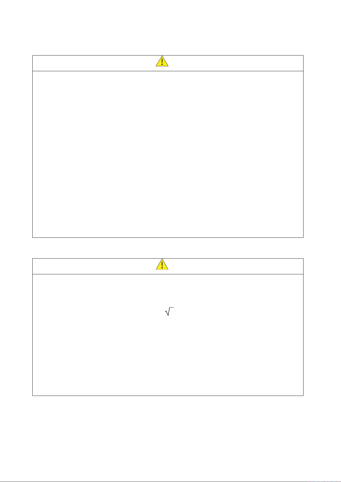
3.3 General Wiring Diagram
AM16
Vcc 24V 12V 5V
R 2KΩ 750Ω 100Ω
Notes:
*1: Models in the range 0.75 ~ 30 kW have a built-in braking transistor. To use this braking transistor a braking resistor
can be connected between B1 and B2.
*2: Use SW3 to select between Sink (NPN, with 24VG common) or Source (PNP, with +24V common) for multi-function
digital input terminals S1~S8.
*3: Use SW2 to switch between voltage (0~10V) and current (4~20mA) input for Multi-function analog input 2 (AI2).
Besides please also check parameter 04-00 for proper setting.
*4: Run Permissive input F1 and F2 is a normally closed input. This input should be closed to enable the inverter output.
To activate this input remove the jumper wire between F1 and F2.
*5: Models from 4 kW include terminals -10V, S(+), S(-),R2A-R2C and PO-GND.
*6. Models up to 2.2 kW include terminal DO2.
*7: When using the open collector for pulse input, it doesn’t need resistance because of built-in pull-up resistance.
*8: AO2 default setting is 0~+10V.
*9 Models 75 kW and 90 kW have built-in DC reactors.
*10 It need turn on the switch for the terminal resistor RS485 in the last inverter when many inverters in parallel
connection. Please refer to Appendix A
12
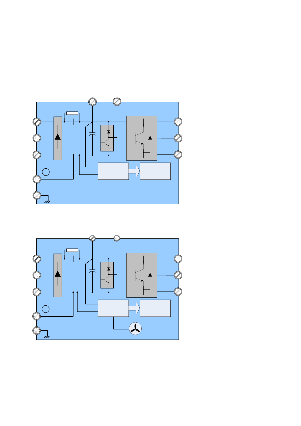
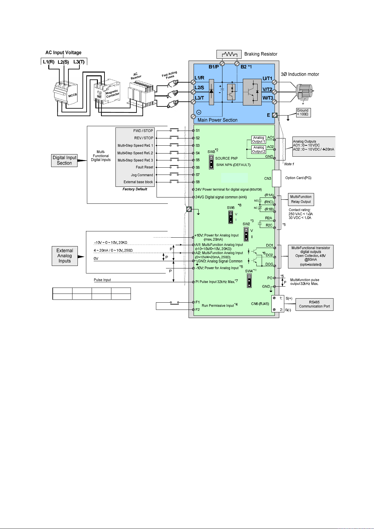
3.4 Input / Output Power Section Block Diagram
The following diagrams 1 - 8 show the basic configuration of the power sections for the
range of horsepower and input voltages. This is shown for reference only and is not a
detailed depiction.
1: 400V: 0.75 ~ 1.5 kW
L1/R
L2/S
L3/T
-
E
2: 400V: 2.2 ~ 30 kW
L1/R
B1/P
+
-
Main Power Section
B1/P
DC /DC
Converter
B2
U/T1
V/T2
W/T3
Control
Circuit
B2
U/T1
L2/S
L3/T
-
E
+
-
DC /DC
Converter
Main Power Section
V/T2
W/T3
Control
Circuit
Cooling Fan
13
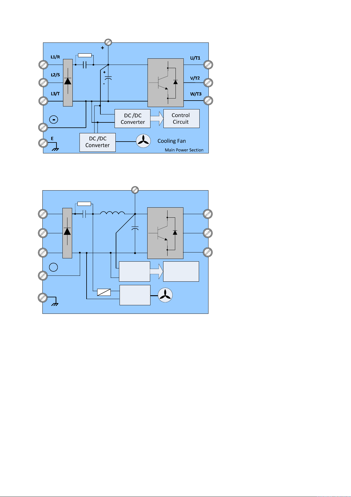
3: 400V: 37 ~ 55 kW
4: 400V: 75 ~ 90 kW
L1/R
L2/S
L3/T
N
E
DC Link
Reactor
Converter
Fuse
Converter
Main Power Section
P
+
-
DC /DC
DC /DC
U/T1
V/T2
W/T3
Control
Circuit
Cooling Fan
14
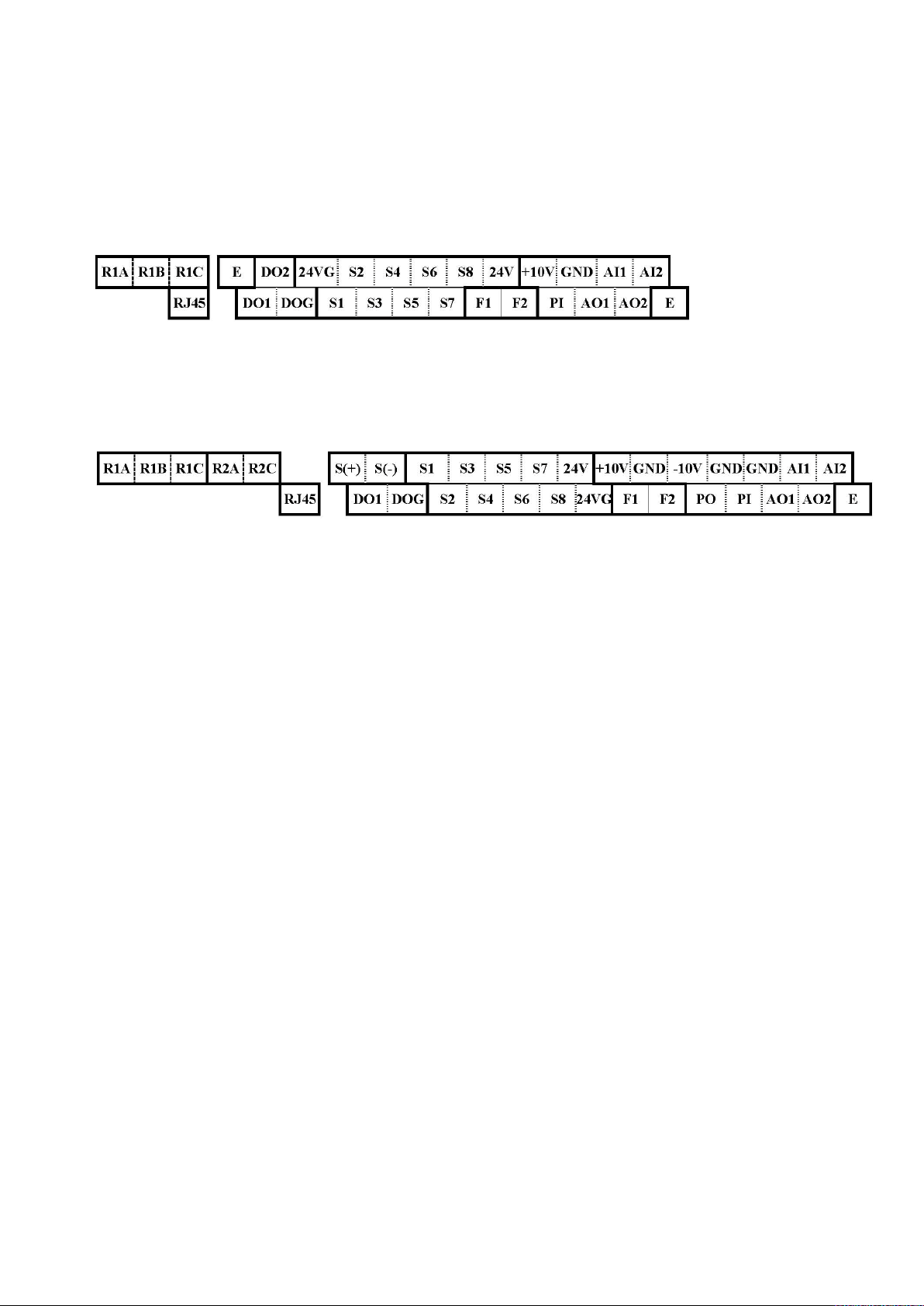
3.5 User Terminals (Control Circuit Terminals)
Models 400V: 0.75 ~ 2.2 kW
Models 400V: 4 ~ 90 kW
15

Description of User Terminals
S1
S2
S6
S7
+10V
GND
GND
GND
Type Terminal Terminal Function Signal Level / Information
2-wire forward/ stop (default) * 1
2-wire reversal/ stop (default) * 1
Multi-speed/ position setting command 1
(default) * 1
Multi-speed/ position setting command 2
(default) * 1
Multi-speed/ position setting command 3
(default) * 1
Fault reset (default) * 1
JOG frequency command (default) * 1
External B.B.(Base Block) stop (coast to stop)
(default) * 1
Digital signal SOURCE point (SW3 switched to
SOURCE )
Common terminal of Digital signals
Common point of digital signal SINK ( SW3
switched to SINK )
Power for external speed potentiometer +10V (Max. current , 20mA)
Only above 200V 3HP/ 400V 5HP (include)
support this terminal function
Multi-function analog input for speed reference
(0-10V input)/(-10V~10V input)
Multi-function analog input terminals *2, can
use SW2 to switch voltage or current input
(0~10V)/(4-20mA)
Analog signal ground terminal ---Shielding wire’s connecting terminal (Ground) ---Multi-function analog output terminals *2
(0~10V output)
Multi-function analog output terminals *2. can
use SW6 to switch voltage or current input
(0~10V / 4-20mA output)
Analog signals ground terminal
Signal Level 24 VDC
(photo isolated)
Maximum current: 8mA
Maximum voltage: 30 Vdc
Input impedance: 4.22kΩ
±15%,
Max. output current: 250mA
(The sum of all loads
connected )
-10V (Max. current , 20mA)
From 0 to +10V,
From -10V to +10V
Input impedance : 20KΩ
Resolution: 11bit + 1
From 0 to +10V,
From -10V to +10V
Input impedance: 200KΩ
From 4 to 20 mA
Input impedance: 250KΩ
Resolution: 11bit + 1
From 0 to 10V,
From 4 to 20mA
(Load < 500Ω)
PWM Frequency: 10KHz
Digital
input
signal
24V
Power
supply
Analog
input
signal
Analog
output
signal
S3
S4
S5
S8
24V
24VG
-10V
AI1
AI2
E
AO1
AO2
GND
Pulse
output
signal
Pulse
input
signal
PO
PI
Pulse output, Band width 32KHz, only above
200V 3HP/ 400V 5HP (include) support this
terminal function.
Analog signals ground terminal ----
Pulse command input,
Bandwidth: 32KHz
Analog signals ground terminal ----
16
Max. Frequency: 32KHz
Open Collector output
L: from 0.0 to 0.5V
H: from 4.0 to 13.2V
Max. Frequency: 0 - 32KHz
Built-in pull-up resistance.
When open collector input is
used, it is not required to
connect resistance.

DO2
DOG
R1A
R1B
R2A-R2C
S (+)
S (-)
Type Terminal Terminal Function Signal Level / Information
DO1
Digital
output
Relay
output
Run
Permissive
Input
RS-485
port
Grounding
Notes:
*1:Multi-function digital input/ output can be referred to in this manual.
200V:1-
2HP
400V:1-
3HP
R1C
200V:over
3HP
400V:over
5HP
F1
F2
E (G)
Multi-function(open collector transistor) output
*1
Open collector transistor digital ground
Relay A contact (multi-function output terminal)
Relay B contact (multi-function output terminal)
Relay contact common terminal,
With the same functions as DO1/DO2
With the same functions as DO1/DO2
On: normal operation.
Off: stop.
(Jumper wired between F1 and F2 has to be
removed by using external contact to stop.)
RS485/ Modbus communication protocol Differential input and output
Grounding to earth
Shield the connecting terminal
48Vdc, 2mA ~50mA
Open-collector output
Rating:
250Vac, 10 mA ~ 1A
30Vdc, 10 mA ~ 1A
Rating:
250Vac, 10 mA ~ 1A
30Vdc, 10 mA ~ 1A
24Vdc, 8mA, pull-up
24V Ground
----
- Group 03: External Terminals Digital Input / Output Function Group.
*2:Multi-function analog input/ output can be referred to in this manual..
- Group 04 - External Terminal Analog Signal Input (Output) Function Group.
Caution
Maximum output current capacity for terminal 10V is 20mA.
Multi-function analog output AO1 and AO2 are used for an analog output meter.
Do not use these outputs for feedback control.
Control board’s 24V and ±10V are to be used for internal control only, Do not use
the internal power-supply to power external devices.
17
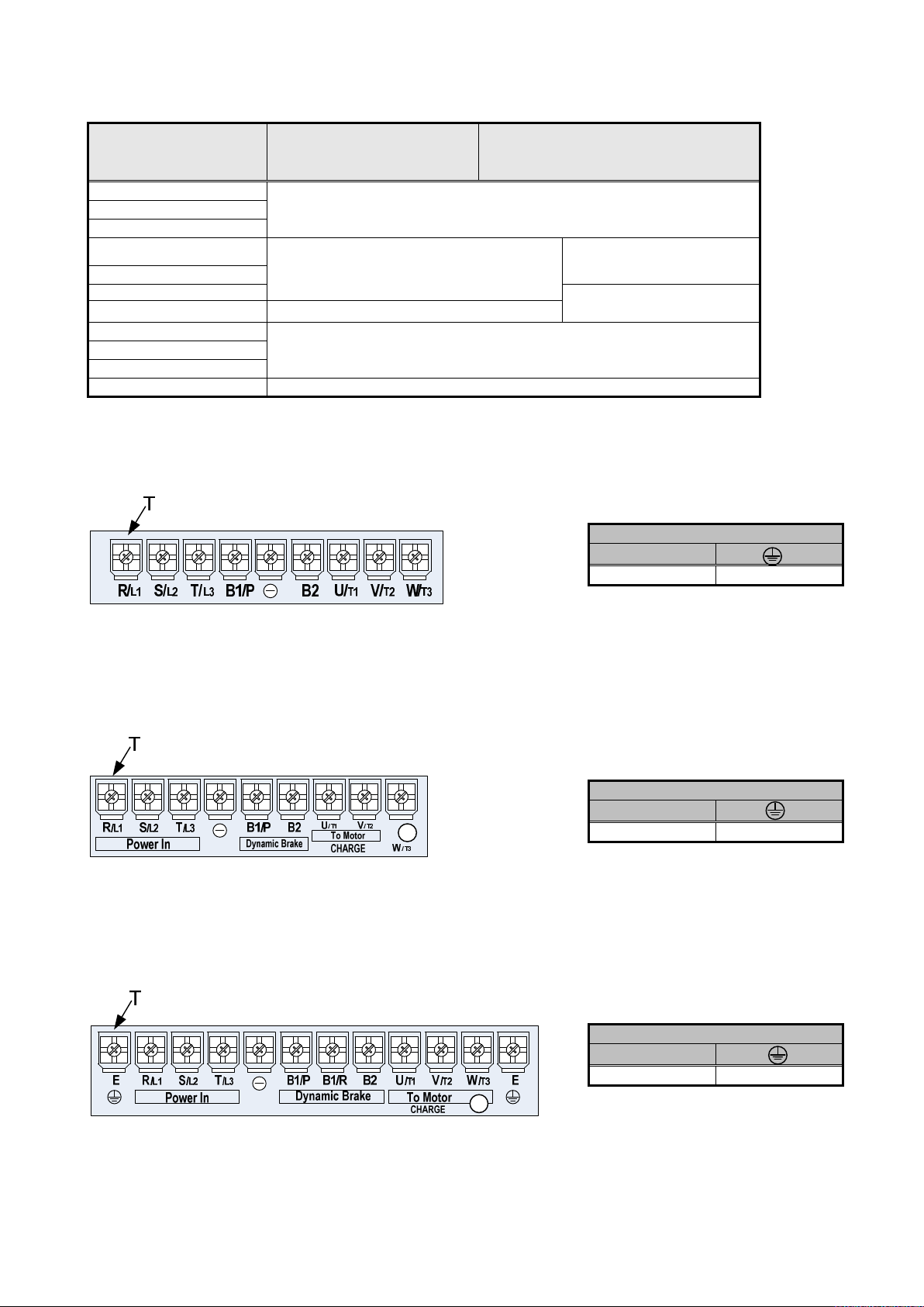
3.6 Power Terminals
: DC power supply or
Terminal screw size
Terminal screw size
Terminal screw size
Terminal 400V: 0.75 ~ 30 kW 400V: 40 ~ 90 kW
R/L1
Input Power Supply (For single phase use terminals R/L1 and S/L2) S/L2
T/L3
B1/P
B2
U/T1
W/T3
E Ground terminal
Models 400V: 0.75 ~ 2.2 kW
B1/P-: DC power supply
B1/P-B2: external braking resistor
-
Inverter output V/T2
-
-
connect braking module
Models 400V: 4 ~ 5.5 kW
Models 400V: 7.5 ~ 11 kW
T
M4 M4
T
M4 M4
18
T
M6 M6
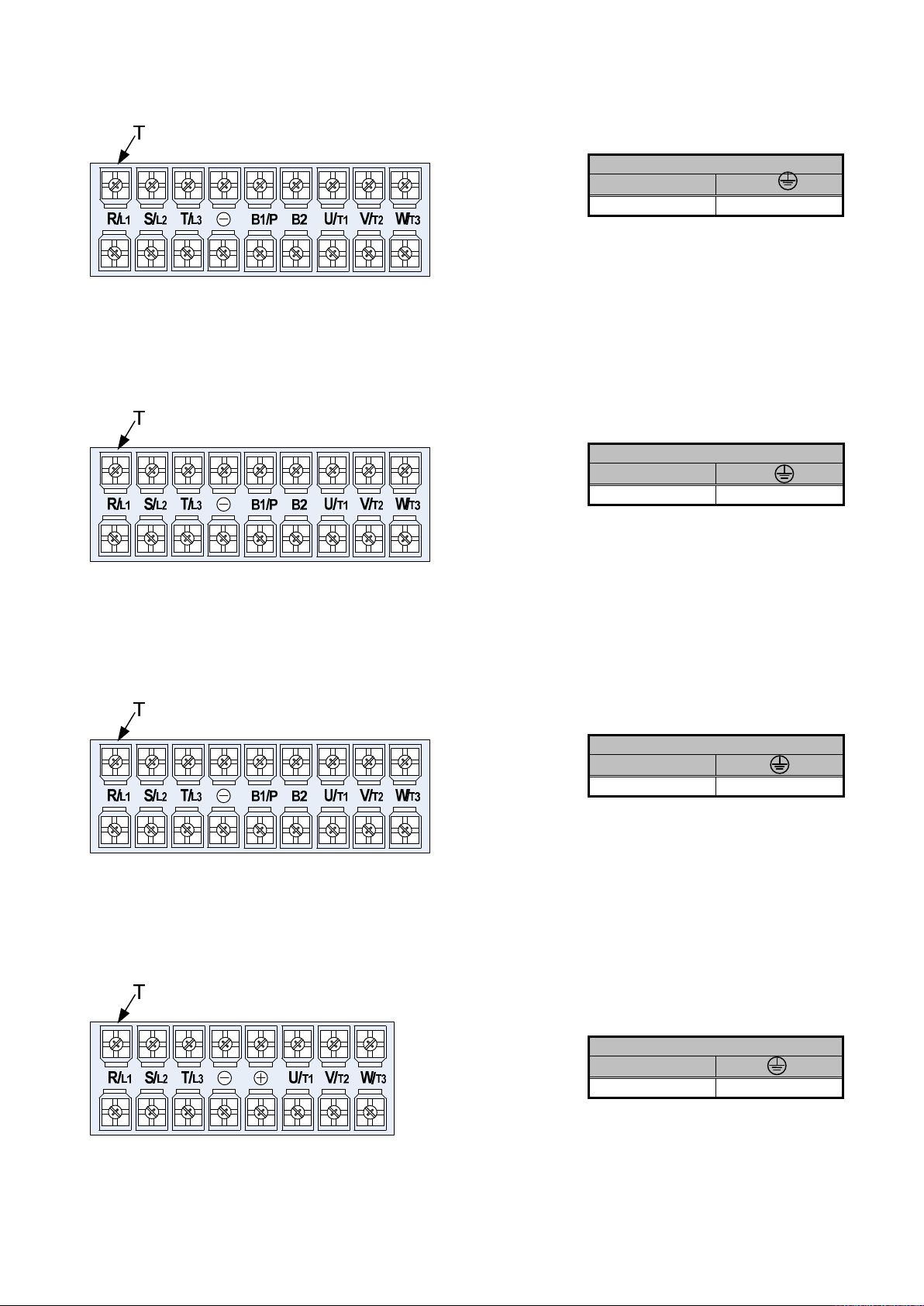
Model 400V: 15 kW (Frame 3)
Terminal screw size
Terminal screw size
Terminal screw size
Terminal screw size
Models 400V: 15 ~ 22 kW
T
M6 M5
T
M6 M6
Model 400V: 30 kW
Models 400V: 37 ~ 55 kW
T
M6 M8
T
M8 M8
19
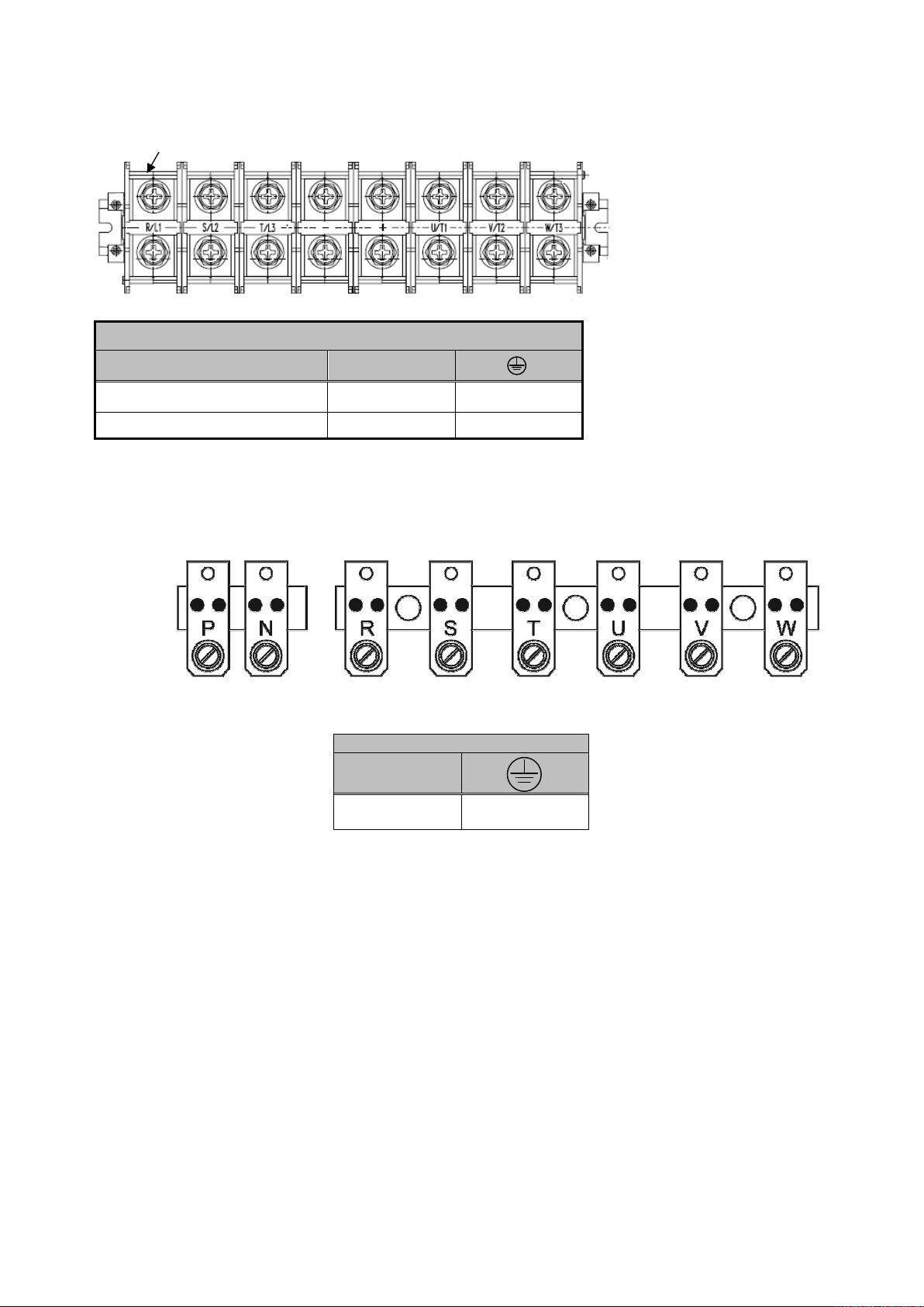
Terminal screw size
T
Model 400V: 75 kW
Terminal screw size
Power supply T
400V 75HP M8 M10
200V 50-60HP/ 400V 100HP M10 M10
Model 400V : 90 kW
T
M10 M10
Notes: For wire gauges and screw torques, please refer to the table in section 3.1.
20
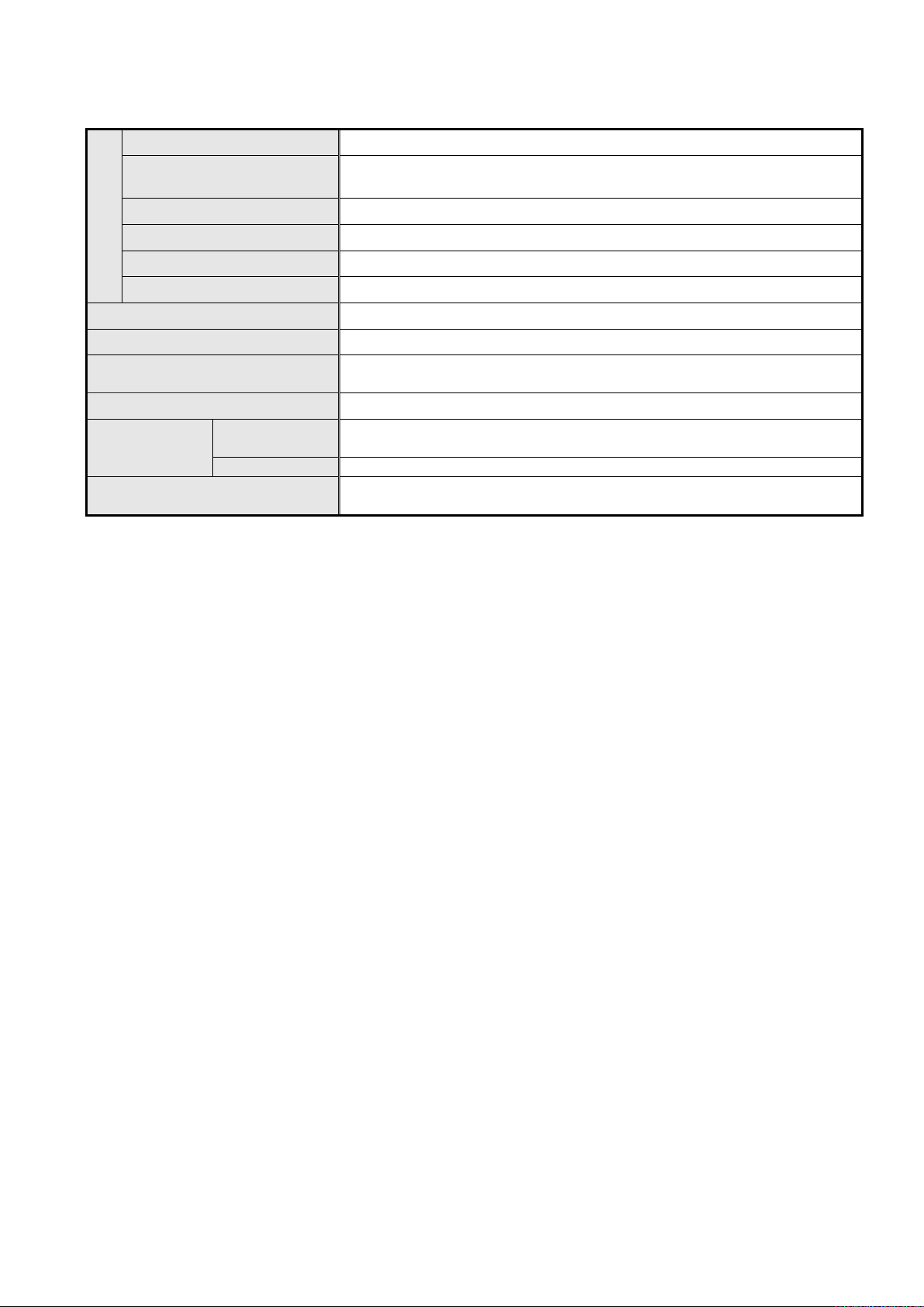
Motor rated current (A)*1
Duty type
Motor rated current (A)*1
y type
(P/N Bar code)
(S/N Bar code)
3.7 Inverter Specifications
Basic Specifications 400V class
Inverter capacity (kW)
Heavy Duty type
H.D.
(150%/1min)
Normal
N.D.
(120%/1min)
Output rated
The maximum output voltage (V)
The maximum output frequency (Hz)
Rated voltage, frequency
Allowable voltage fluctuation
Power
Allowable frequency fluctuation
Rated output Capacity (KVA)
Rated output current (A)
Maximum applicable motor *1 (KW)
Rated output Capacity (KVA)
Rated output current (A)
Maximum applicable motor * (KW)
Motor rated current (A)*1
Inverter capacity (kW)
Heavy Duty type
H.D.
(150%/1min)
Normal Dut
N.D.
(120%/1min)
Output rated
The maximum output voltage (V)
The maximum output frequency (Hz)
Rated voltage, frequency
Allowable voltage fluctuation
Power
Allowable frequency fluctuation
Rated output Capacity (KVA)
Rated output current (A)
Maximum applicable motor *1 (KW)
Rated output Capacity (KVA)
Rated output current (A)
Maximum applicable motor *(KW)
Motor rated current (A)*1
0,75 1,5 2,2 4 5,5 7,5 11 15 18,5 22
2.6 3.2 4.2 7 11.3 13.7 18.3 23.6 29.7 34.3
3.4 4.2 5.5 9.2 14.8 18 24 31 39 45
0,75 1,5 2,2 4 5,5 7,5 11 15 18,5 22
1.7 3.1 4.2 7 10.1 12.6 18.6 24.8 31.1 36.3
3.1 4.1 5.3 9.2 13.3 17.5 23.6 29.0 33.5 44.2
4.1 5.4 6.9 12.1 17.5 23 31 38 44 58
1.5 2.2 4 5.5 7.5 11 15 18.5 22 30
3.1 4.2 7 10.1 12.6 18.6 24.8 31.1 36.3 48.7
3-phase 380V~ 480V
Based on parameter setting 0.1~599.0 Hz
3-phase 380V ~ 480V, 50/60Hz
-15% ~ +10%
±5%
30 37 45 55 75 90
45.7 57.2 69.3 89.9 114 137
60 75 91 118 150 180
30 37 45 55 75 90
48.7 59 70.5 88 114 145
55.6 67.1 78.5 111 128 159
73 88 103 145 168 208
37 45 55 75 90 110
59 70.5 88 114 145 175
3-phase 380V~ 480V
Based on parameter setting 0.1~599.0 Hz
3-phase 380V ~ 480V, 50/60Hz
-15% ~ +10%
±5%
Double motor rating corresponding to H.D. and N.D. is reported within inverter nameplate.
Name-plate double rating
21

Inverter Voltage
HD mode
HD mode
400V class
*1: Take AM16 standard 4-pole induction motor as the base.
*2: AM16 model is designed to use in heavy duty (H.D.) conditions, the factory setting is the HD (Heavy Duty type) mode.
*3: The overload capacity of AM16 model HD (Heavy Duty) is 150% / 1min, 200% / 2sec. See the table below for the
carrier frequency default setting and range.
*4: The overload capacity of AM16 model ND (Normal Duty) is 120%/1min, carrier range: 2 KHz ~ 16 KHz, the default
setting is 2 KHz.
*5: If it is greater than default carrier frequency, you need to adjust the load current based on the de-rating curve.
and Capacity
0.75~22 kW 2~16KHz 8KHz
- 2~12KHz 6KHz
30~37 kW 2~12KHz (*6) 5KHz
45~90 kW 2~10KHz (*6) 5KHz
*6: If control mode (00-00) is set to 2 (SLV mode) and maximum frequency (01-02) is larger than 80Hz, the carrier
frequency range is 2~8 KHz.
carrier frequency range
carrier frequency factory setting
22

The following table shows maximum output frequency for each control mode.
Duty Cycle
Control mode
Other settings
Maximum output frequency
HD mode
(00-27=0)
Normal Duty
(00-27=1)
V/F
V/F + PG
SLV2
SLV 400V 0.75~11 kW 150Hz
400V 15 kW 110Hz
400V 15~22 kW 100Hz
SV unlimited 599Hz
PMSV unlimited Twice of Base frequency
PMSLV unlimited Base frequency
V/F
V/F + PG
SLV /SV
PMSV/ PMSLV
SLV2
maximum frequency set to
599Hz
400V 30~90 kW, carrier (11-
01) is set as 8K or below 8K
maximum frequency set to
120Hz
No normal duty mode
599Hz
100Hz
120Hz
-
23

General Specifications
setting is 8~2KHz. ND mode: If inverter rated
Operation mode
Control mode V/F, V/F+PG, SLV, SV, PMSV, PMSLV, SLV2* with space vector PWM mode
Frequency control range 0.1Hz~599.0Hz
Output frequency accuracy
(Temperature change)
Speed control accuracy ±0.1% ( vector control(SV)),±0.5% ( vector control / open-loop)
Frequency setting resolution
Output frequency resolution
Inverter overload
Frequency setting signal 0 to +10VDC / 4 to 20mA or -10V to +10VDC and pulse input command frequency
Acceleration / deceleration time 0.0 - 6000.0 second (separately set acceleration and deceleration time )
Voltage, frequency
characteristics
Control characteristics
Braking torque +/- 20%
Main control functions
Other functions
Stall protection
Instantaneous over current (OC)
and output short-circuit (SC)
protection
Inverter overload Protection
(OL2)
Motor overload (OL1) protection Electrical overload protection curve I²T
Over voltage(OV) protection If the main circuit DC voltage rises over 820V (400V class), the motor stops running.
Under voltage (UV)
Automatic restart after
Protection functions
instantaneous power fault
Overheat protection(OH) Uses temperature sensor for protection.
Ground Fault protection(GF) Use current sensor for protection.
LCD keypad with parameter copy function (Optional Seven-segment display * 5 +
LED keypad)
Digital references: ±0.01%(-10 to +40°C) Analog references: ±0.1% (25°C ±10°C )
Digital references: 0.01Hz, Analog references: 0.03Hz/60Hz (If the maximum output
frequency of motor is over 300HZ,the frequency resolution is changed to 0.1Hz )
0.01Hz (If the maximum output frequency of motor is over 300HZ,the frequency
resolution is changed to 0.1Hz )
Rated output current 150%/1 min, 200%/2sec (HD mode),120%/1 min (ND mode)
Factory 150%/1 min, 200%/2sec
Custom V/f curve based on parameters
Auto-tuning, Zero Servo, torque control, position control, Droop, Soft-PWM, overvoltage protection, dynamic braking, speed search, frequency traversing,
instantaneous power fault restart, PID control, automatic torque compensation,
automatic speed regulation, RS-485 communication standard, speed feedback
control, simple PLC function, 2 sets of analog outputs, safety switch.
Accumulated power-on / run time, 30 sets of fault history records and latest fault
record state, energy-saving function setting, single phase protection, smart braking,
DC braking, Dwell, S curve acceleration and deceleration, Up / Down operation,
MODBUS protocol, pulse output, engineering units, SINK / SOURCE digital inputs.
Stall prevention level can be set independently in acceleration, deceleration and
constant speed.
Inverter stops when the output current exceeds 200% of the inverter rated current.
HD mode: If inverter rated current 150%/1 min., or 200%/2sec is exceeded inverter
stops, factory default carrier frequency
current 120%/1 min is exceeded inverter stops , factory default carrier frequency is
2KHz.
If the main circuit DC voltage falls below 380V (400V class), the motor stops
running.
Power fault exceeds 15ms.
Automatic restart function available after instantaneous power fault in 2sec.
DC bus charge indicator When main circuit DC voltage ≧50V, the CHARGE LED turns on.
Output Phase Loss Protection
(OPL)
If the OPL is detected the motor stops automatically.
24
Location
Ambient temperature
Storage temperature
Humidity
Environment
Specification
Altitude and vibration
Pollution Degree
Communication function
PLC function
EMI protection
EMS protection
Certification
Option
CE
UL
Indoor (protected from corrosive gases and dust).
-10~+40°C (14°F~104°F) (IP20, -10~+50°C (14°F~122°F) (IP00) ) without derating; with de-rating, its maximum operation temperature is 60°C (140°F)
-20~+70°C (-4°F~+158°F)
95%RH or less ( no condensation )
Altitude of 1000m (3181ft) or below ; 1.0G, IEC60068-2-6
Meet IEC 60721-3-3 Class 3C2
RS-485 standard (MODBUS RTU / ASCII protocol) (RJ45)
Built-in
The built-in noise filter complies with EN61800-3 available for inverters 400V 40kW
or below.
EN61800-3
EN61800-3 (CE & RE)
EN61800-5-1 (LVD)
UL508C
JN5-PG-O/ JN5-PG-L/ JN5-PG-PM/ JN5-PG-PMR/ JN5-PG-PMS/ JN5-PG-PMC
Encoder Card
25
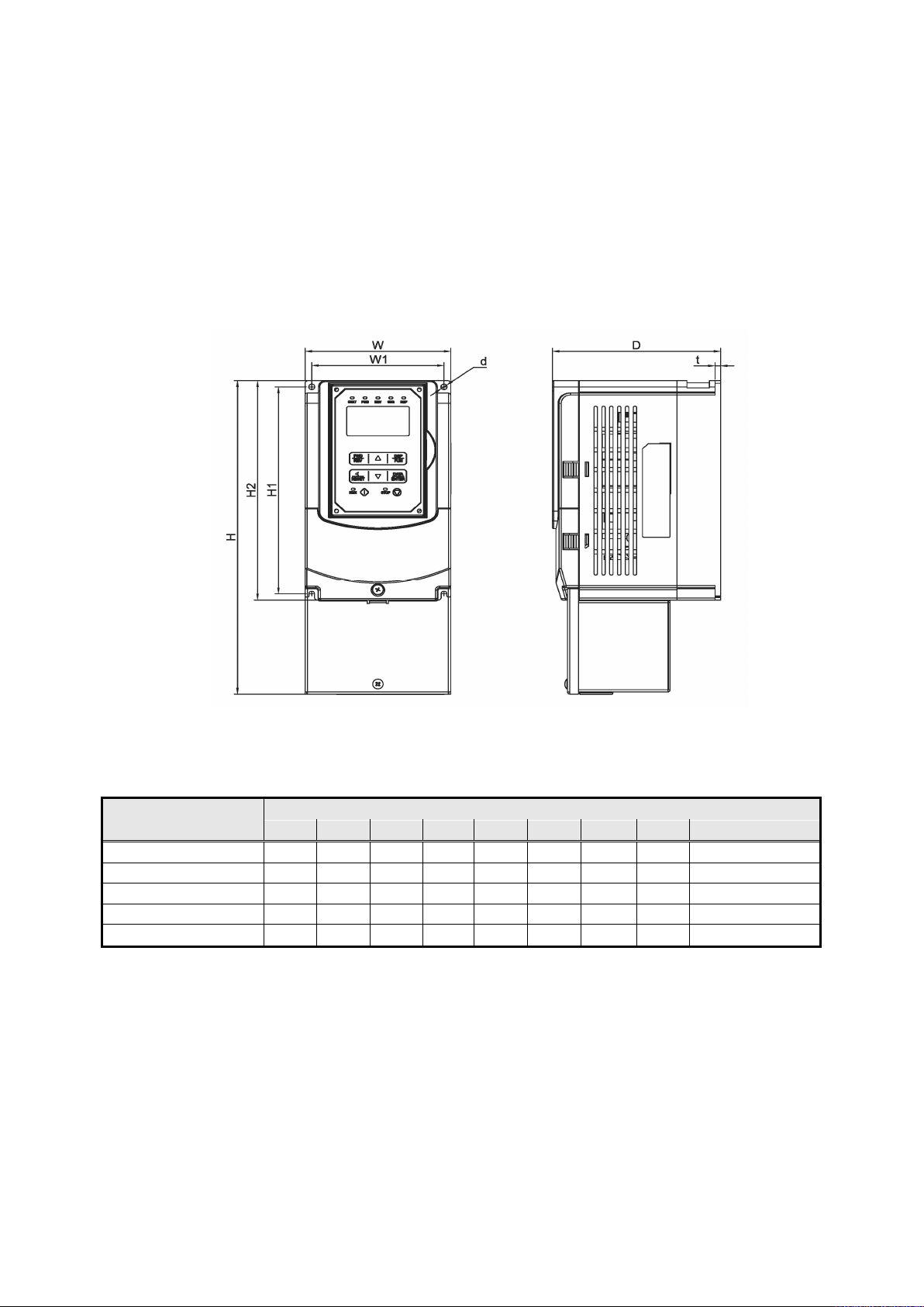
3.8 Inverter Dimensions
Models with Built-in Filter
(a) 400V: 0.75 – 5.5 kW (IP20)
Inverter Model
AM16-340-0075-F-20 130 306 150 118 203 215 5 M5 3.5
AM16-340-0150-F-20 130 306 150 118 203 215 5 M5 3.5
AM16-340-0220-F-20 130 306 150 118 203 215 5 M5 3.5
AM16-340-0400-F-20 140 400 177 122 267 279 7 M6 5.5
AM16-340-0550-F-20 140 400 177 122 267 279 7 M6 5.5
W H D W1 H1 H2 t d Net Weight (kg)
Dimensions (mm)
26
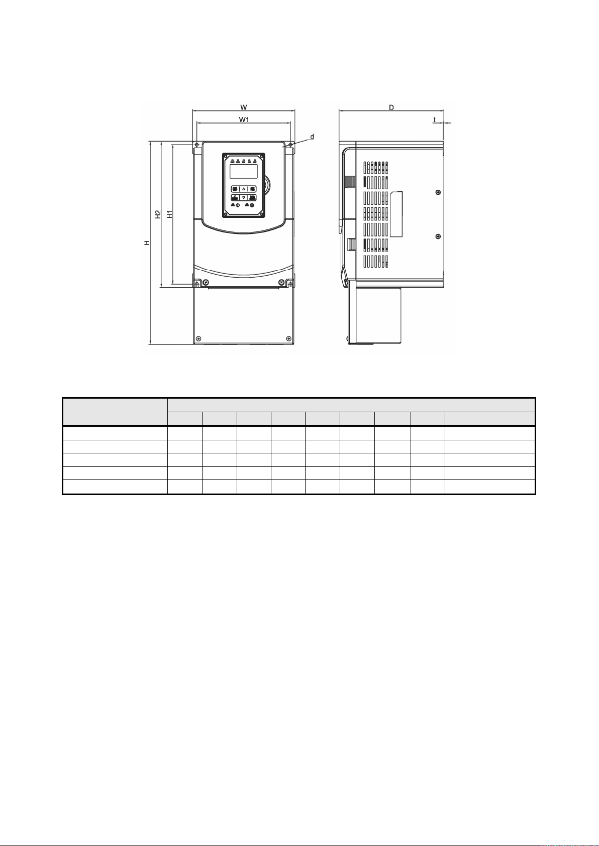
(b) 400V: 7.5 – 22 kW (IP20)
12.5
12.5
Inverter Model
AM16-340-0750-F-20 210 416.5 215 192 286 300 1.6 M6 8.0
AM16-340-1100-F-20 210 416.5 215 192 286 300 1.6 M6 8.0
AM16-340-1500-F-20 265 500 225 245 340 360 1.6 M8 12.5
AM16-340-1850-F-20 265 500 225 245 340 360 1.6 M8
AM16-340-2200-F-20 265 500 225 245 340 360 1.6 M8
W H D W1 H1 H2 t d Net Weight (kg)
Dimensions (mm)
27
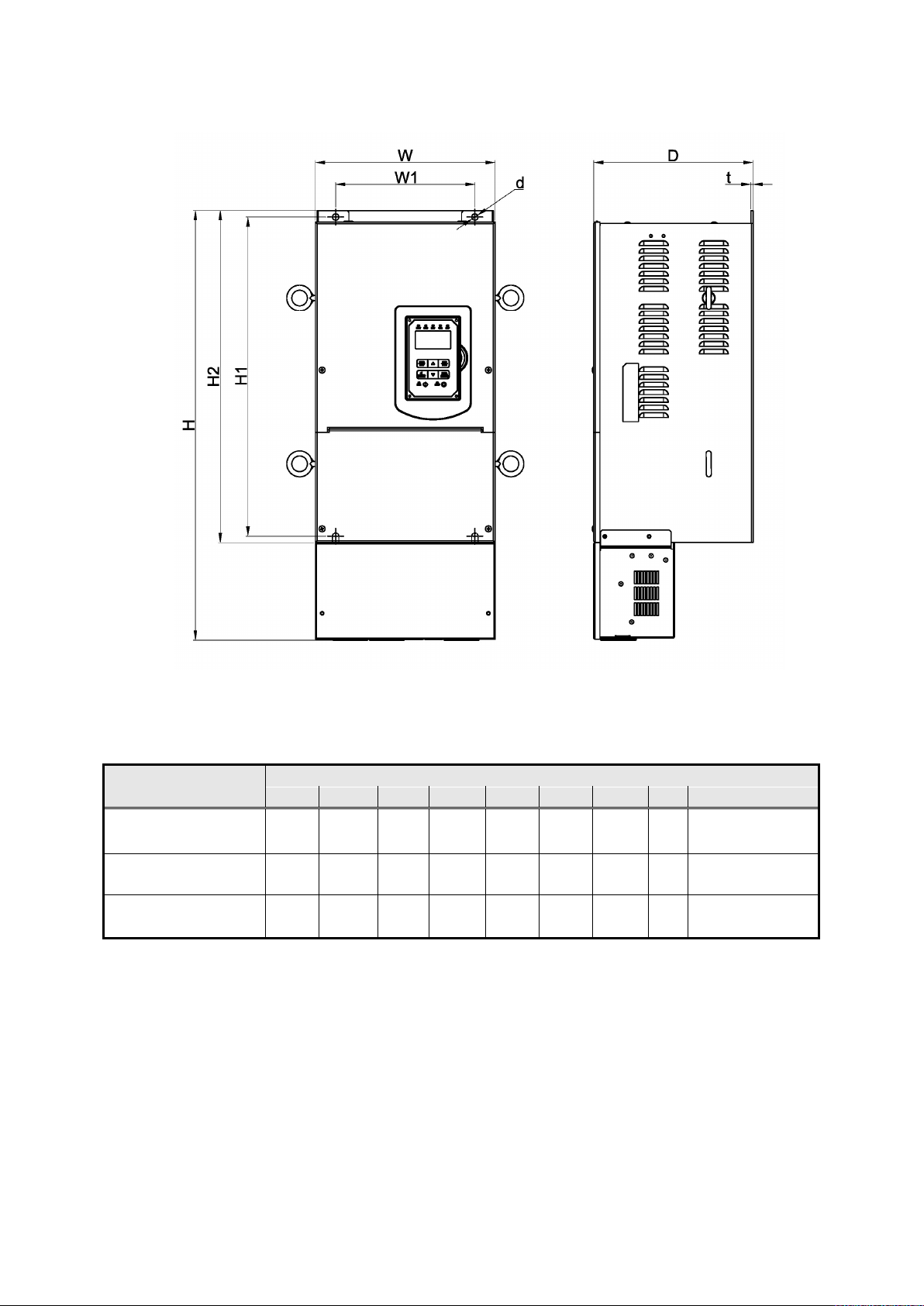
(c) 400V: 30 – 45 kW (IP20)
Inverter Model
AM16-340-3000-F-20 286.5 679 252 220 505 525 3.3 M8 32.5
AM16-340-3700-F-20 286.5 679 252 220 505 525 3.3 M8 32.5
AM16-340-4500-F-20 286.5 679 252 220 505 525 3.3 M8 32.5
W H D W1 H1 H2 t d Net Weight (kg )
Dimensions (mm)
28
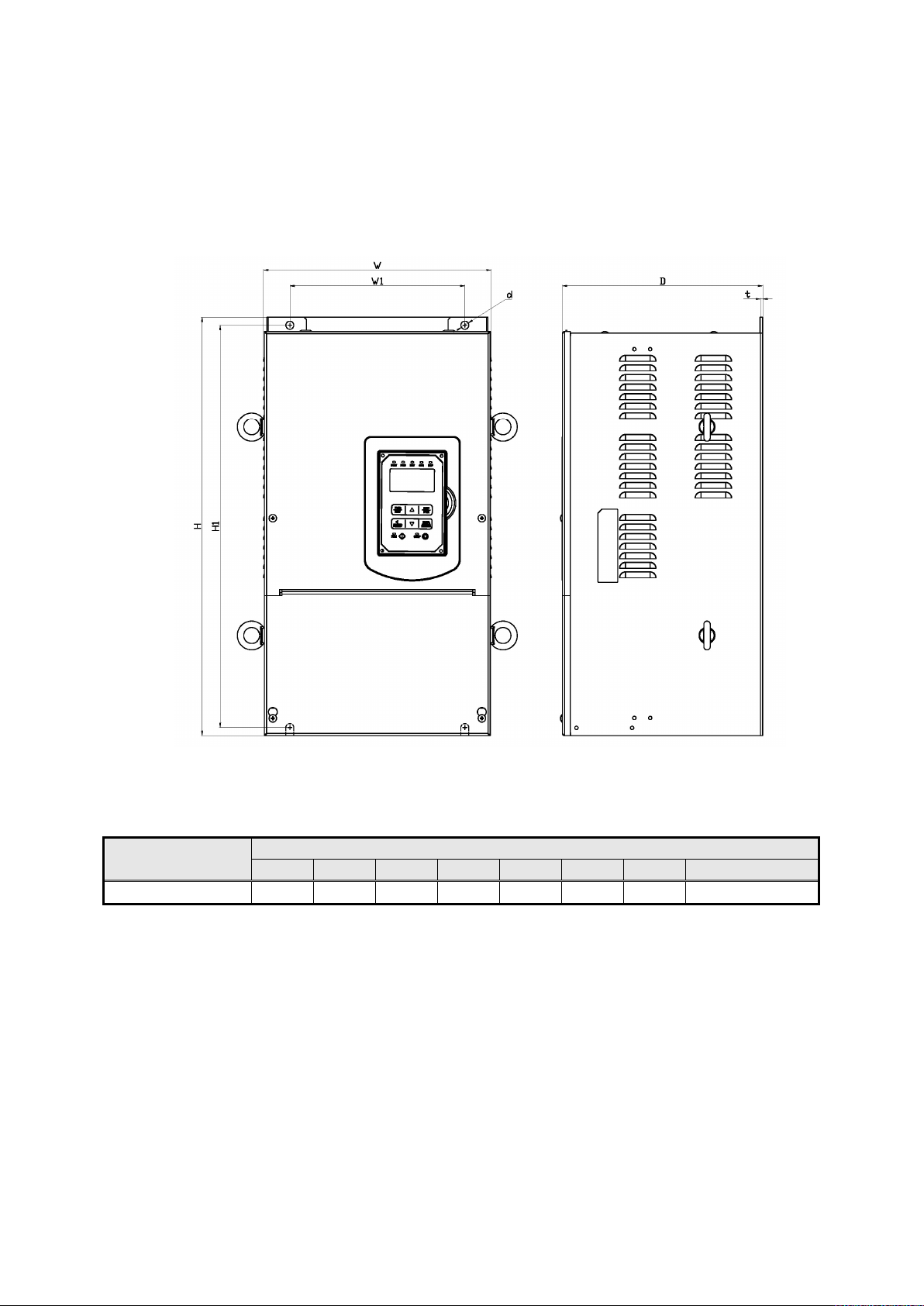
Models without internal Filter
(a) 400V: 55 kW (IP20)
Inverter Model
AM16-340-5500-20 286.5 525 252 220 505 3.3 M8 35
W H D W1 H1 t d Net Weight (kg)
Dimensions in (mm)
29
 Loading...