

Motostar Stylstar Installation Manual
AUTAUT
AUTAUT
AUT
OMAOMA
OMAOMA
OMA
TION FOR SWING GATION FOR SWING GA
TION FOR SWING GATION FOR SWING GA
TION FOR SWING GA
TESTES
TESTES
TES
INSTALLATION MANUAL
STYLSTSTYLST
STYLSTSTYLST
STYLST
ARAR
ARAR
AR

2
CONTENTS
1.0 Standard system description page 3
1.1 Description of the gearmotor unit components page 3
2.0 General characteristics page 4
2.1 Technical characteristics of the gearmotor page 4
2.2 Dimensions of the gearmotor and control panel page 4
2.3 Use limits page 5
3.0 Installing the unit gearmotor page 5
4.0 General characteristics of the control panel page 9
4.1 Assembling and securing the control panel page 9
4.2 Description of the control board page 10
4.3 Main components of the control board page 11
4.4 Electrical connections page 12
4.5 Check test for operating the photoelectric cells page 15
4.6 Radio code programming page 15
4.7 Function selections page 16
4.8 Functions adjustments page 18
4.9 Adjusting the limit switch page 19
5.0 LED control functions page 20
6.0 Maintenance page 20
3
1
2
3
4
5
6
s
t
y
l
s
t
a
r
1
2
3
4
5
E
1
2
3
4
4
5
7
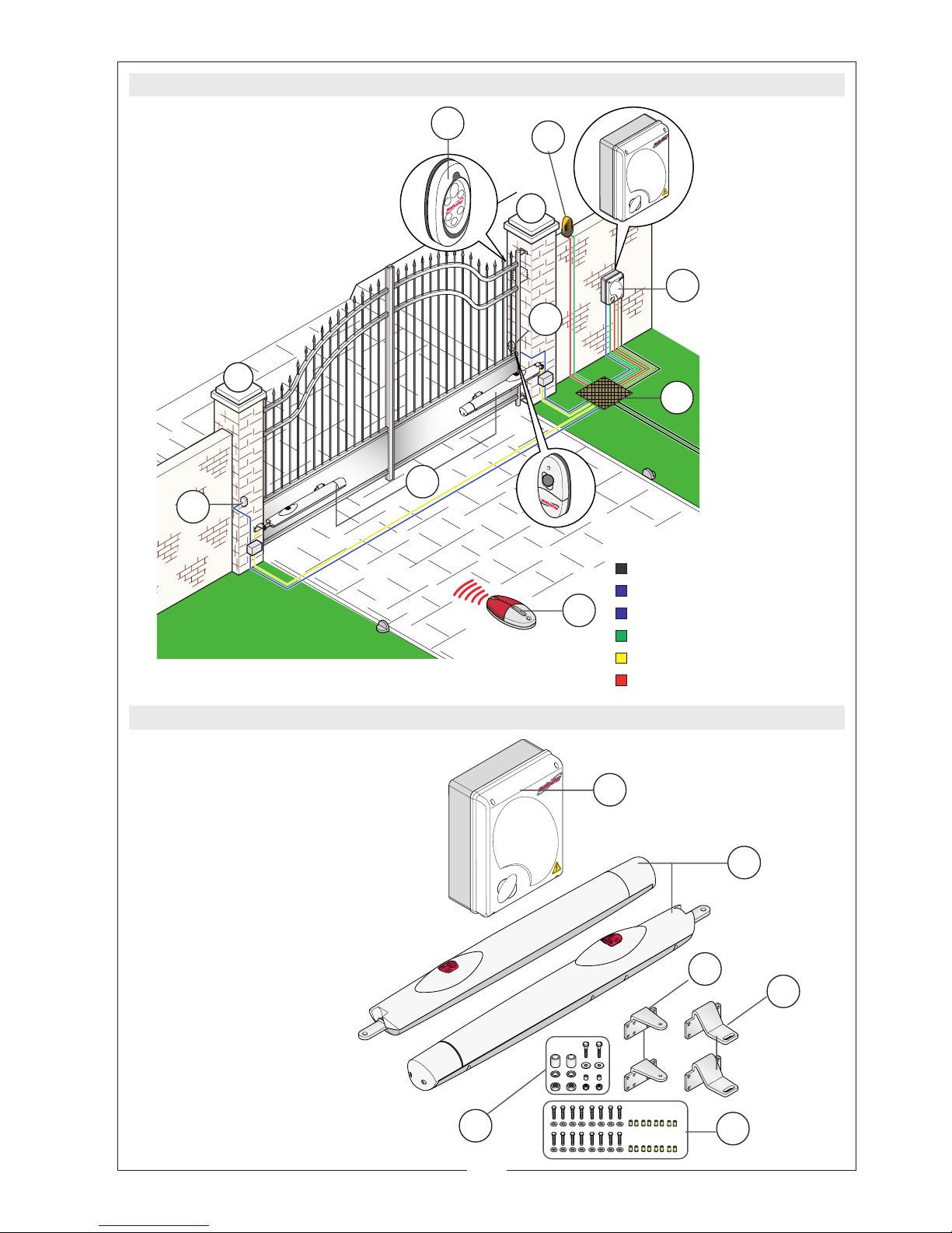
1.0 STANDARD SYSTEM DESCRIPTION
1.1 DESCRIPTION OF THE GEARMOTOR UNIT COMPONENTS
1)Flashing lamp with
incorporated reception antenna
2) Radio keyboard
3) Control panel
4) Photoelectric cell
5) Raceway for electric cables
6) Gearmotors
7) Transmitter
1) Control panel
2) Gearmotors
3) Tail brackets for pillar
4) Head brackets for gate wing
5) Screws, washers, bushings and
locking nuts for gearmotors
6) Screws, washers, bushings and
locking nuts for brackets
6
Number of wires per cable
section:
- power supply: 3 x 1,5
- photocellulas RX: 4 x 0,5
- photocellulas TX: 2 x 0,5
- flashing lamp: 2 x 1,5
- gearmotor: 3 x 1,5
- antenna: RG58
4
Automation for swing gates up to 2.20 meters per wing with 230V AC power and IP54
protection, equipped with:
- self-learning of the code between transmitter and radio receiver;
- end-stop unit inserted into the front part of the automation, that manages the wing’s stop
during opening and the slowing during closing, with simple adjustments using distance
ring (supplied);
- adjustable amperometric detector that, when an obstacle is encountered, reverses the
wings’ movement during closure and opening;
- dedicated exit in the control panel for connecting a supplementary lamp;
- colored terminal boards to identify the various accessories and simplify the connections;
- Signalling LEDs: power present, programming and safety tests;
- Signalling LEDs for safety: re-opening during closure not active;
- emergency release with three-lobed key;
- power supply cable gearmotor L=2.5m;
- transformer thermoprotection.
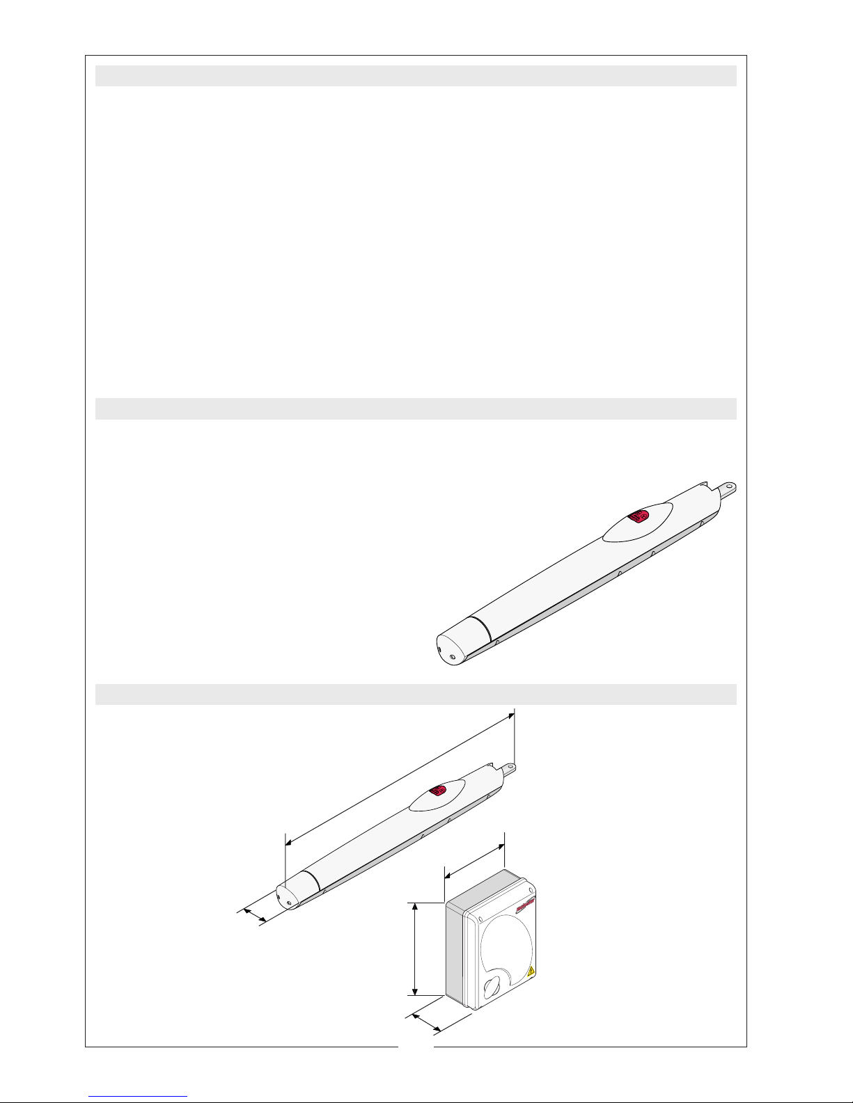
2.1 TECHNICAL CHARACTERISTICS OF THE GEARMOTOR
2.0 GENERAL CHARACTERISTICS
2.2 DIMENSIONS OF THE GEARMOTOR AND CONTROL PANEL
Electromechanical, 24V DC non-reversible single-phase gearmotor, powered by the 230V
AC control panel.
Electric panel power supply: 230V AC. - 50/60Hz
Gearmotor power supply : 24V D.C.
Capacity: 100W
Rated current: 4A max.
Adjustable thrust: 400-2000N
Max use frequency: 45 cycles/h
Operative intermittence: 50%
Reduction ratio: 1/36
Operating temperature: from -20° to +70°C
Weight of the complete pack: 30 kg
900
240
85
135
320
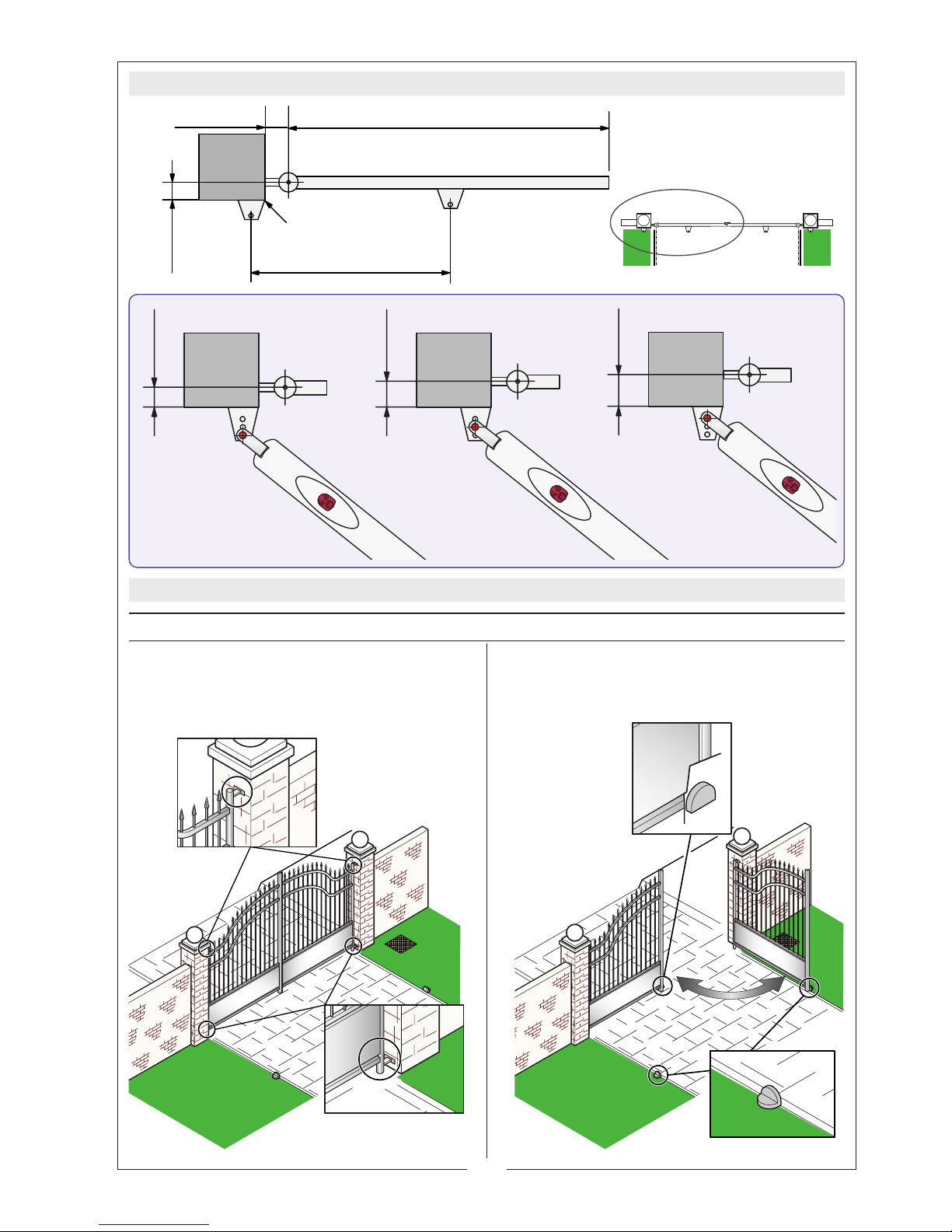
5
3.0 INSTALLING THE GEARMOTOR UNIT
• Check that
the frame
of the gate is robust
enough and that
the hinges
are efficient.
• That there is a mechanical
stop block
for
closing and opening (fixed well to the
ground) to avoid overstop of the wing.
INSPECTING THE GATE BEFORE INSTALLATION
2.3 USE LIMITS
710 mm
100 mm
max.
Max 2200 mm
Max 300 Kg
Max 50 mm
60 mm
80 mm
100 mm
Position the bracket
flush with the pillar

6
710
• Prepare the tubes for the electrical con-
nections and install connector blocks on
both sides of the gate.
• Check on the wing the (suitable) zone
for securing the head bracket, take the
measurement and return it to the pillar.
Secure the tail bracket (see application
drawings).
• Secure the tail bracket to the pillar using
suitable fixing accessories chosen depending on the shape of the fixing material. For metal
pillars, use the
bushings, washers and screws
supplied.
• Position the head bracket on the wing
horizontally to the tail bracket at 710 mm
distance.
• Secure the bracket with bushings, wash-
ers and screws supplied.
• From the raceway, insert the electric ca-
bles into the tubings, respecting the section and number of cables depending of
use (see system on page 3).
Head bracket
Tail bracket
==
==
> 120
< 120
PREPARING THE SHEATH TUBINGS, CONNECTOR BLOCKS WITH AND BRACKET
ASSEMBLY.
 Loading...