

MotoSAT H3 User And Installation Manual
H3
H3 is available in a “Stand alone”
or a 1RU Rack Mount
Mobile Satellite Antenna Controller
User and Installation Manual
Firmware Version 1.0.9
16 February 2011

The DataStorm H3 Satellite Antenna Controller
H3
Features
Stand Alone Satellite Antenna Controller
Front Panel Search, Stow, and Power Commands
No Software Required on PC
DVB-S2 Satellite Identification (NID)
HTML Graphical User Interface
SD Card Firmware Upgrades
SD Card Configuration Imports
Web Direct Sat Table Imports
LED Status Indicators
Simplified Multiple Sat Select Screen
Telnet Commands for Diagnostics
Import and Export Configuration Files
Import and Export Satellite Tables
Simple Electrical Connections
HTML and Telnet Security
The DataStorm H3 Satellite Antenna Controller
The DataStorm H3 Satellite Antenna Controller is one of the most advanced Satellite Antenna
Controllers available. Simple User operation combined with many advanced configurable
features will allow the flexibility needed for almost any application anywhere.
Operate from the Front Panel or through a PC using an Internet Browser such as
Internet Explorer, Firefox, Sapphire, Chrome or many other Browsers.
No external software is required.
A true stand alone Satellite Antenna Controller now with SD Card Interface.
NOTE: The DataStorm H3 Satellite Antenna Controller can be used with
either the
• Automatic pole mount (MESA) which stows in a “bird bath” position
or the
• Mobile automatic mount (MESSENGER) which stows in a “face
down” horizontal position.
The H3 Antenna Controller is available in either a “Stand alone” or “Rack
Mount” configuration.
This manual is written to use the “face down horizontal” mount as an
example and was written to reference the Stand Alone style.
2

Table of Contents
Getting Started 5
Connection and Configuration 5
Using the SD Card for Setup 5
Quick Setup 5
H3 Normal Operation 8
Front Panel Operation 8
HTML Operation 10
Find a Satellite 11
Stow Dish 14
Standard Functions 15
System Status (Main Page) 15
Modem Status 17
About 18
Configuration Functions 19
Network Settings 19
Search Settings 22
RF Settings 35
Mount Settings 47
Advanced Functions 60
Manual Motor Control 60
Calibrate Dish 61
Import/Export Files 63
Upgrade Firmware 65
SD Card Functions 68
SD Autoload 68
SD H3 Files 68
SD LoadOnce 68
Manuals 68
3

H3 (System) Wiring 69
H3 Rear Panel 69
H3 Bottom View 70
Wiring Diagram 71
Serial Cable (Optional) 72
Power Supply 72
Specifications 73
Mechanical 73
Electrical 74
Diagnostics 75
Controller Start Up Test 75
Telnet Diagnostics 76
Telnet Screens 77
Message Codes 82
DataStorm H3 Messages Codes 82
4

Getting Started!
If this is a new system install or just upgrading to the new H3 Controller it is
important to follow the guidelines below to insure the system functions properly.
Connection and Configuration!
Nearly all technical support calls on new installations are due to bad or improper
wiring, or incorrect configurations. Please be sure to review these two items
before contacting technical support for assistance.
The H3 must be configured properly before it can be used in normal operation.
Before proceeding insure that all wiring to the H3 Controller is correct. This
would include any connections to the DataStorm Mount. See H3 System
Wiring.
Using the SD Card for Setup
The H3 Satellite Antenna Controller includes a Front Panel SD Card Slot. This
feature will allow the user to upgrade firmware, import configuration files, and
import Sat Tables without being connected to a PC or Network. See SD Card
Functions for setup and use.
Note: A PC with a USB Adaptor or SD slot will be needed to modify the SD Card
Config files.
Quick Setup
Once the System is installed and wired the next step is to prepare the H3 Controller for
the users specific requirements.
Below is a quick list to follow to insure proper operation. Please follow the steps below
in the order as shown.
• Step 1 Set up a Network Connection between the H3 and the PC
Using the SD Card, LoadOnce Folder, place a modified configuration file in the
LoadOnce folder.
Name the file “IPConfig.txt” and place the IP information needed to work in the
existing Network (Router)
5

LocalAddr = 192.168.1.250 /new controller IP address
SubnetMask = 255.255.255.0 /if different
ModemIp = 192.168.0.1 /modem IP address
GateAddr = 192.168.1.1 /router IP address
Place the SD Card into H3 SD Card Slot, turn ON power. When controller
restarts IP Info is changed.
See Network Settings page 19.
• Step 2 Upgrade Firmware (If necessary)
Using the SD Card, LoadOnce Folder, place a new H3firmware.hex file in the
LoadOnce folder.
Place into H3 SD Card Slot, turn ON power. Wait for status indicators to scroll
from left to right. When controller restarts the new firmware is updated.
See Upgrade Firmware page 63.
• Step 3 Calibrate Dish
See Calibrate Dish page 59.
• Step 4 Modify Configuration Functions
Open the HTML Browser and choose the Configuration Functions pages;
Search Settings (all) - Satellite System, Satellite Longitude, and RX Polarity
Search Settings (HNS) - TX Polarity, Modem IF Frequency, Symbol Rate
LNB Settings – As necessary
See Configuration Functions page 19.
Note: See Import/Export Files to save configuration page 61.
• Step 5 Ready for Normal Operation (Find Satellite)
Open the HTML Browser and click on the Search command.
See Find a Satellite page 11.
• Step 6 Import a current Sat Table
Once the Dish Mount is locked to the correct satellite and the Modem has come
into the network you should update the Sat Table.
6

Import Web Sat Table allows the user to directly import the latest Satellite Table
File from the MotoSAT Web Site. In Network Settings (Web Sat Table URL) is a
default web address of http://www.motosat.com/sattables/world.csv. This address
can be changed if future sites are available. For this import to work the user must
be connected to an active modem (Network) and locked onto the Satellite.
See Import/Export Files page 61.
• Step 7 Save Configurations and Sat Tables
Once the H3 Controller and Dish Mount have been set up properly the Current
Sat Table and Config Files should be exported.
See Import/Export Files page 61.
After exporting these files to the PC, remove the SD Card from the H3 Card Slot
and connect the SD Card to your PC. Save the Config file and Sat Table to the
H3 Files Folder on the SD Card for backup. Place SD Card back into H3
Controller.
The H3 Files Folder is used to store different Firmware versions, and different
Dish Mount configuration files samples. This is just a working folder on the SD
Card. The H3 Controller can not read or write any files to this folder.
7
H3 Normal Operation
IMPORTANT! Before the H3 is ready for normal use the system must be wired
and configured correctly. Go to Setup and Configuration for setup.
The H3 Controller can be operated through either Front Panel Controls or via
the HTML Interface built into the Controller.
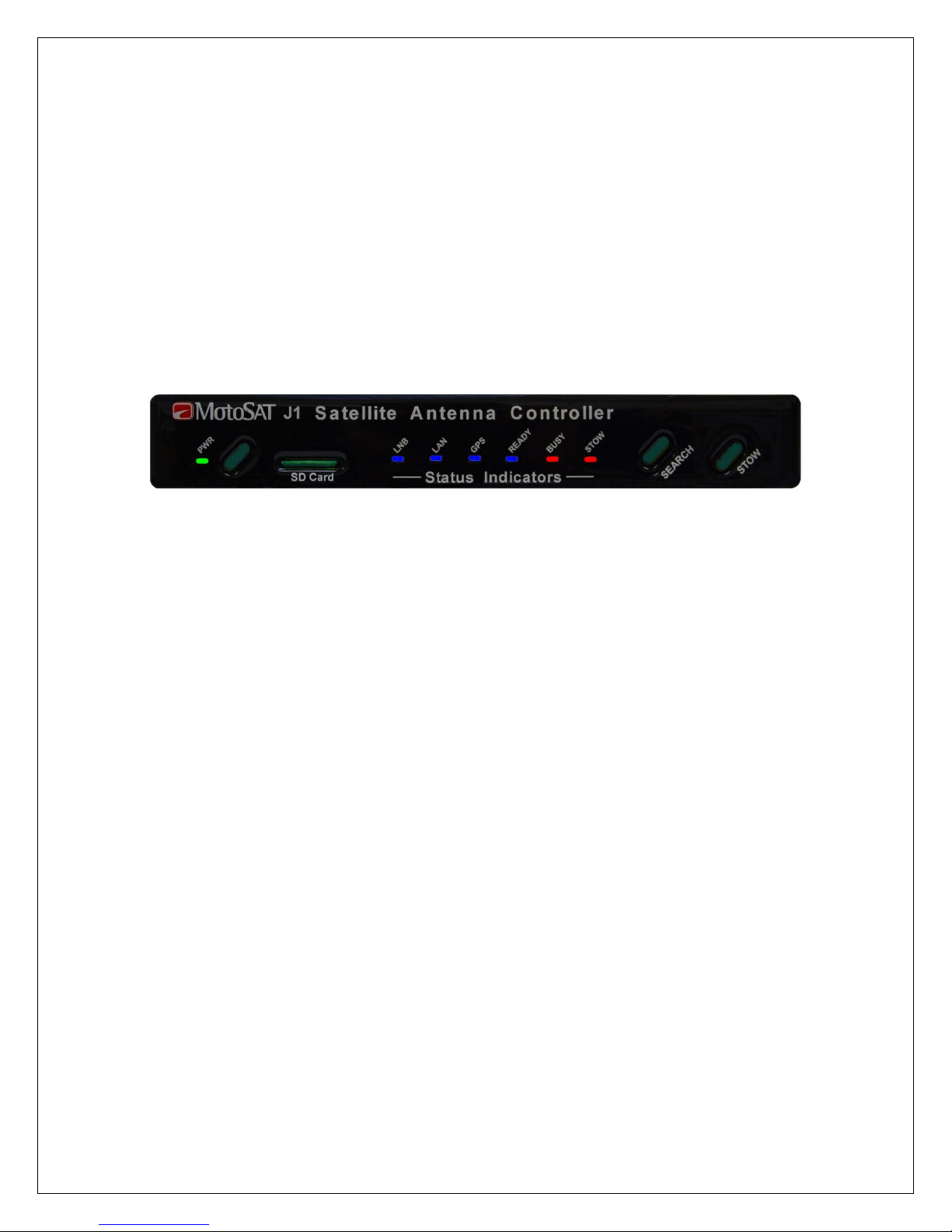
Front Panel Operation
Model H3
The Front Panel
The Power Button is used to turn the H3 Controller ON and OFF. When
powered ON, the Green LED to the Left of the Power Button will illuminate.
On power up the controller will take about 15 seconds to initialize. The Power,
LNB, and LAN LED’s should be illuminated when controller is ready for use.
Under normal conditions the Stow LED should also be illuminated when first
powered on. (After a Calibrate Dish or normal Dish Stow)
The Search Button will cause the Antenna to rise from the stowed position and
search for the Default Satellite. (The Satellite Longitude entered on the Search
Configuration Page.)
When the Search Button is pressed the BUSY and READY lights will start to
flash.
The GPS light should be illuminated (GPS Locked) before the Antenna will start a
Search (move).
If the GPS Light is blinking the Antenna will not move until the GPS Light goes
solid. A blinking GPS means that a valid GPS location has not been
determined. Typically GPS should acquire lock in less than 120 seconds.
NOTE: If GPS is set to Manual then the Dish will begin Search
immediately.
has three Buttons.
8

The Stow Button when pressed will move the Antenna to the its respective stow
postition. When the Antenna is moving to the Stowed position the Busy and
Stow Light will flash. When the Antenna is stowed the Stow Light will be on
Solid.
The Front Panel
Power Light (Green) is illuminated when the H3 is powered ON.
LNB Light (Blue) will illuminate when a Modem is connected to the H3 and
power is applied to the Modem. If the H3 is configured to Generic Mode then the
H3 will supply LNB power.
LAN Light (Blue) is illuminated when a network connection is detected.
GPS Light (Blue) will illuminate when GPS has received a valid Latitude and
Longitude location. When GPS is not locked LED will Blink.
If there is no GPS (Sensor Board) installed on the Antenna Mount then the GPS
light will be off.
READY Light (Blue) will illuminate when the Target Satellite is locked and
peaked.
The Ready Light will flash when the Antenna is searching for a Satellite.
BUSY Light (Red) illuminates under many conditions.
On Power Up the Busy light will flash for approximately 15 seconds while the H3
Controller is initializing the system configuration.
During Search and Stow the Busy light will flash.
STOW Light (Red) is on Solid when the Antenna is Stowed in its respective
stowed position. When the Antenna is moving to the stow position the Stow Light
will flash.
has seven (7) lights.
9
HTML (Web Browser) Operation
IMPORTANT! The LAN Light must be ON before the web browser can open.
To use the HTML Interface you must access the H3 by using a standard Web
Browser such as Internet Explorer, Netscape, or Mozilla. Open the Browser as
you normally would then type into the address bar the IP Address of the H3
Controller. The default IP address of the H3 is set to 192.168.1.250. This
address can be changed in the Network Settings Screen.
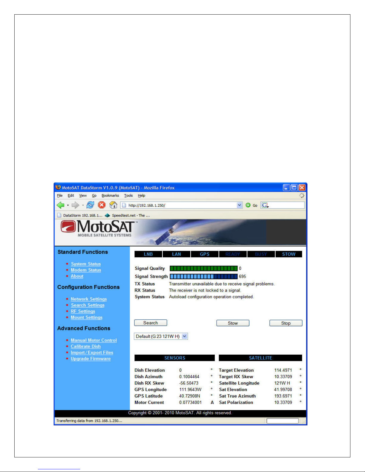
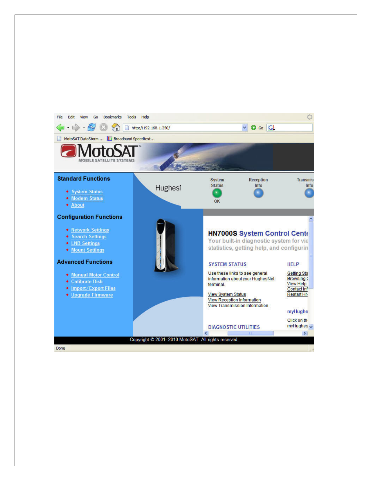
The System Status screen should open if the browser and H3 IP address are
configured correctly. See Setup and Configuration if the page below does not
open.
System Status Screen Antenna Stowed
10
Find a Satellite (Search)
Before the System will begin a search the LNB and LAN status indicators must
be illuminated.
The GPS indicator will illuminate when valid GPS is acquired.
Clicking on the Search button will cause the Antenna to begin a search
for the Default Satellite. (Also referred to as the Target Satellite.)
A Drop Down Box below the Search Button allows the user to select any Satellite
Configured in the Sat Table. Highlight the desired Satellite and click the Search
button.
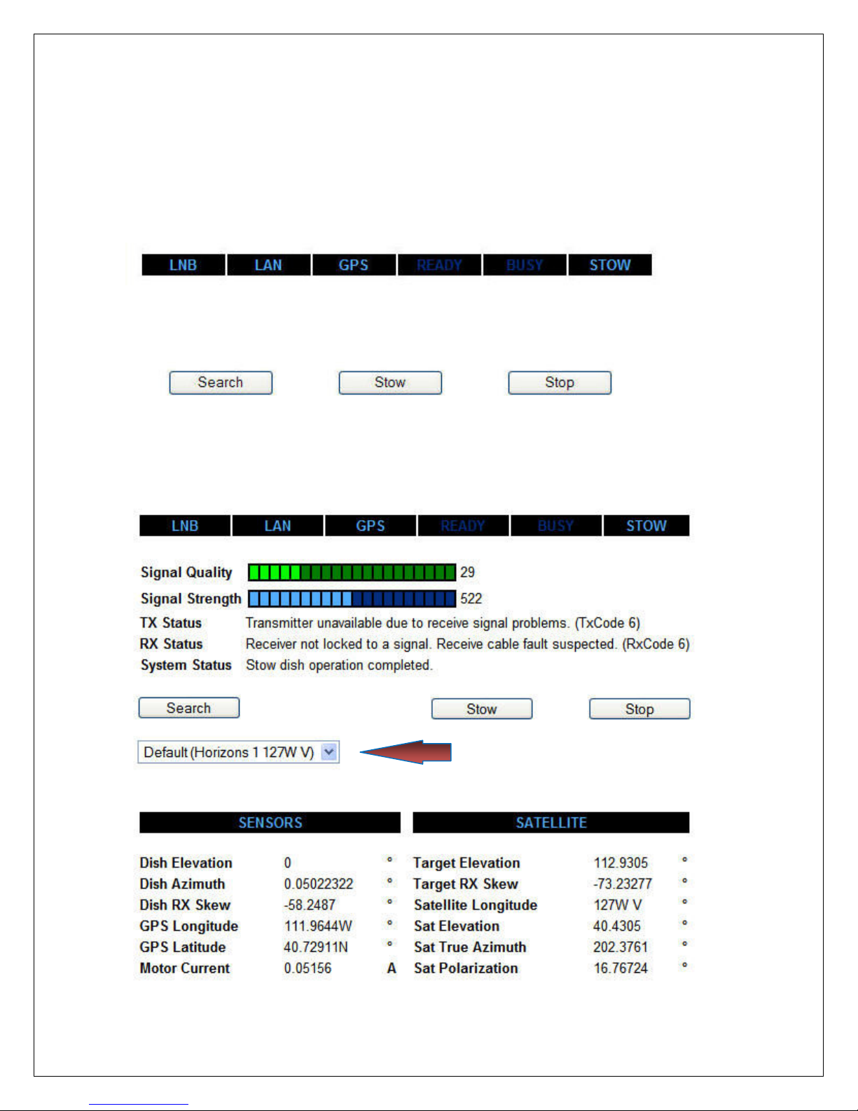
Satellite Selector Screen Antenna Stowed
11
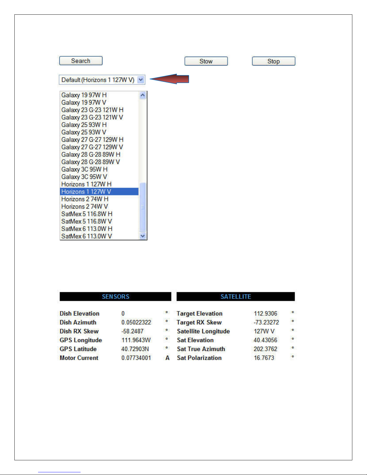
Satellite Selector Screen Drop Down Table
The arrow above is showing the current default
satellite in the Drop Down box.
The Default Satellite is created in Search
Settings. (Satellite Longitude)
By clicking on the Down Arrow in the Drop
Down box, a list of all available satellites will
Appear in the Sat Table window.
The size and order of these satellites can be
configured Search Settings. See Search
settings.
After highlighting the desired satellite in the Sat
Table window, clicking the Search button will
begin the search for the selected satellite.
The Sensors and Satellite Status located on the lower part of the screen will
display the Antenna Mount position and the current Satellite information while the
Search is in progress.
System Status Screen Searching Sky
Under normal search conditions the H3 Controller will search for a Reference
Satellite(s) that is near the true southern part of the sky based upon the current
GPS Longitude.
12
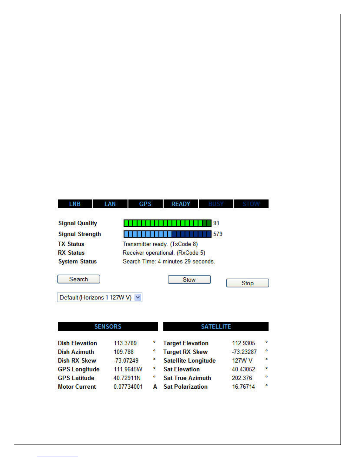
The H3 may find and peak several satellites before identifying a valid satellite.
Once a Reference Satellite is identified the H3 will calculate and move directly to
the Selected Target Satellite.
The H3 will peak the satellite for maximum Signal Quality at that location. After
the peak is completed the H3 will reconfirm the Target Satellite Identification.
NOTE: There are conditions where the Antenna can peak into an adjacent
Satellite because of stronger signal levels. If this happens the H3 Controller will
ID that Satellite and then re-peak to the Target Satellite as described above.
NOTE: There are two types of Searches available in Search Settings. The
default search is referred to as a Longitude Search. The alternative Search is
referred to as Target Search. We recommend the default setting. See Setup
and Configuration for details.
Search Operation completed the system is ready for use.
System Status Screen Search Complete
13
Stow the Dish (Stow)
Stowing the Dish puts the antenna back into its respective stowed position where
the Antenna is in a Face Down or Face Up position
Clicking on the Stow button will cause the Antenna to begin the Stow routine.
The System will begin to stow and the H3 Front Panel will show Stow and Busy
Lights flashing. The HTML Status Screen will show Stowing Dish.
The typical stow routine will cause the antenna to first move elevation to a full
back position, then rotate Skew to a correct stow position, then rotate Azimuth
fully counterclockwise, and then finish stowing to its respective stowed position.
When using the Generic mode type in Search Settings, Satellite System the
antenna elevation is moved up above the Satellite Belt first to prevent any
undesired transmissions from hitting any other satellites during stow.
When using specific modems such as iDirect and Hughes (HNS) the H3
Controller has the ability to disable the Transmit function of the Modem.
When these modems are selected in Search Settings, Satellite System the
Antenna will not need to move elevation up before stowing the antenna.
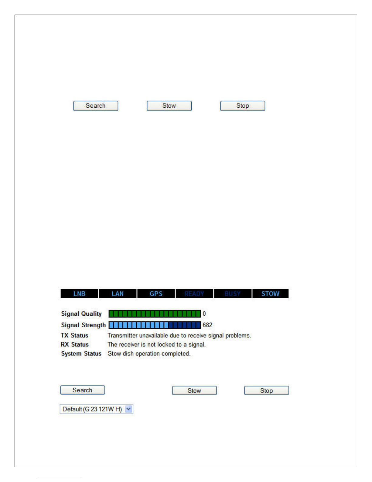
The HTML Screen will show Stow Dish Operation Completed.
System Status Screen Stow Operation Complete
14
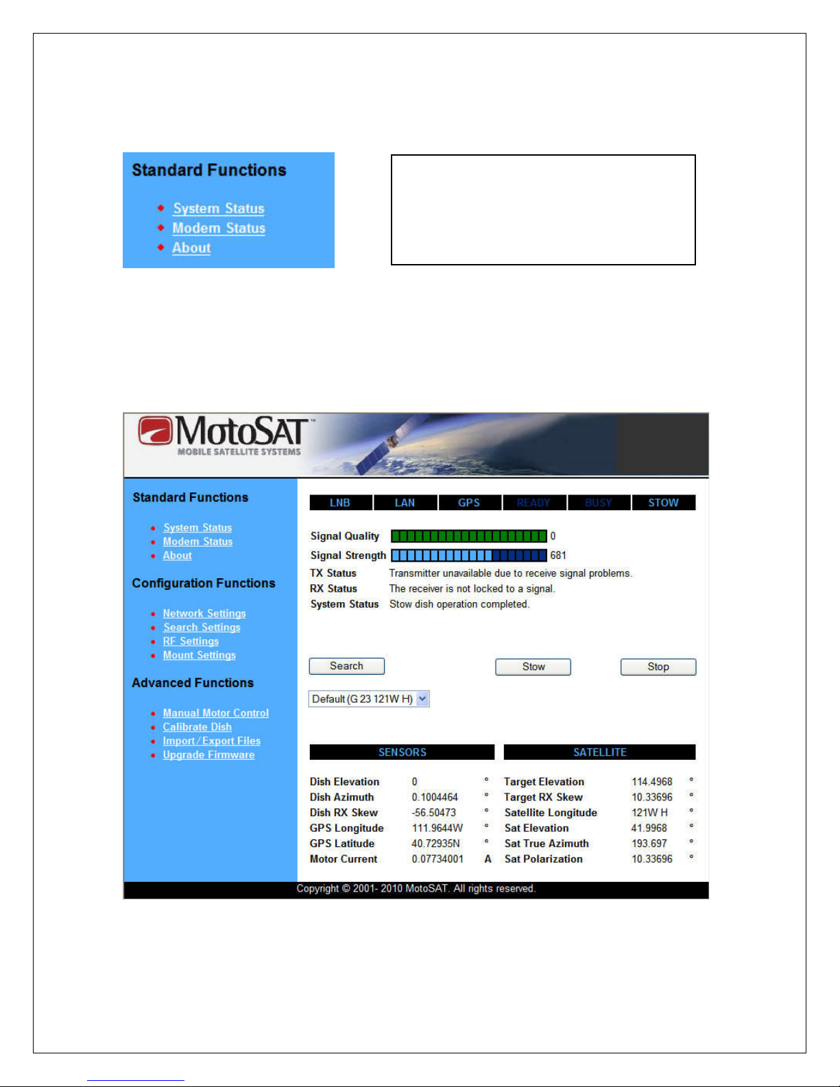
Standard Functions
•
System Status Page
• Modem Status Page
• About Page
System Status Page
The System Status Page is the first screen (main index page) the H3 controller
will open when using HTML. From this page all other functions can be accessed.
System Status Page
15

The main frame of the System Status page (white) includes the Search, Stow
and Stop Commands along with status indicators. In the lower area of the Status
page mount and satellite position information is displayed.
Sensors
Dish Elevation displays the current position of the Antenna in respect to it
respective stowed position. Stow is approximately 0 degrees. Elevation
Origin under Mount Settings will affect this value.
Dish Azimuth displays the current position of the Antenna in the
horizontal travel plane (0 to 375 degrees of rotational travel) relative to the
stowed position.
Dish RX Skew displays the current position of the Antenna Skew.
Depending on Mount Type the Antenna or Feed Horn Assembly will rotate
(roll) in a CW/CCW direction up to +/- 103 degrees. Skew stow position is
different for different mount types.
GPS Longitude and Latitude is read from the GPS module located on
the Antenna Mount or when Manual Location is “Enabled” in Search
Settings.
Motor Current displays the power consumption of the motors on the
Antenna Mount when the Antenna is moving.
Satellite
Target Elevation displays the calculated amount of Elevation travel the
antenna mount will have to raise from the Stowed position to locate the
selected satellite.
Target RX Skew displays the calculated Skew Angle for the selected
satellite.
Satellite Longitude displays the true Longitude location of the Target
Satellite above the Equator.
Sat Elevation displays the true elevation look angle of the Target Satellite
from the Earth horizon (level).
Sat True Azimuth displays the actual compass direction of the Target
Satellite in reference to True North.
Sat Polarization displays the true Skew Angle for the Target Satellite.
16
Modem Status Page
The Modem Status Page currently is available only for the Hughes (HNS)
Modems. This link offers a direct connection to the HNS Status page as shown
below.
Modem Status Page
17
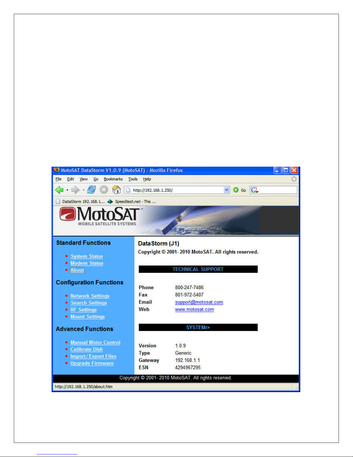
About Page
The About Page offers general information about MotoSAT and the H3
Controller.
As shown below you will find MotoSAT information such as Phone Numbers, Fax
Numbers, Email Accounts, and our Web Address.
You will also find H3 Controller information like Firmware Version, Modem Type,
Router/Gateway IP Address and Modem or internal ESN (serial) numbers.
Occasionally check the MotoSAT Website for newer Firmware Versions.
About Page
18

Configuration Functions
•
Network Settings Page
• Search Settings Page
• RF Settings Page
• Mount Settings Page
The H3 Controller is compatible with two MotoSAT Antenna Mounts. These are
the MESA and MESSENGER. Along with the type of mount, adjustments for
Satellite Location, LNB Frequencies, Polarity and many other options need to be
set for the H3 to function properly based on user application. The following pages
below describe how this is done.
Network Settings Page
The Network Settings Page allows the user to configure the LAN (Local Area
Network) so the H3 Controller, Satellite Modem, and the Router/Switch can all
communicate with each other.
Network Settings Page Page 1 of 1
19

Config Name (Default)
Local Address (192.168.1.250) Setting required
The Local Address is the internal Ethernet Address of the H3 Controller.
This address is set at 192.168.1.250 from the factory but can be changed
based on the customer network requirements.
Subnet Mask (255.255.255.0) Setting required
Default to 255.255.255.0, see your IT manager if changes to this value are
necessary.
Modem Gateway (192.168.1.1) Setting required
This value is set to the modem address. See Modem manual for more
information.
Router Gateway (192.168.1.1) Setting required
This value is set to the Router address. If a LAN switch is used then
setting this to the modem address is typical. See Router or Modem
manuals for more information.
DNS Address (192.168.1.1) Setting required
This value is set to the modem address. See manuals or white papers for
more information.
Modem Username (admin)
If required. Currently the iDirect Modem is the only Modem that requires
a Modem Username to access their Telnet to read SNR (Signal Quality)
and feed it GPS for mobile use. The default Username is admin but the
ISP or VAR can change this. A -25 message will appear on the main
status page if this name is not correct.
Modem Password (*********) (P@55w0rd!)
If required. Currently the iDirect Modem is the only Modem that requires
a Modem Username and Password to access their Telnet to read SNR
(Signal Quality) and feed it GPS for mobile use. The default Password is
set internally but will display ******** on this screen. Contact the ISP or
VAR if this requires changing. A -25 message will appear on the main
status page if this password is not correct.
20

Web Sat Table URL (http://www.motosat.com/sattables/world.csv)
The H3 Satellite Antenna Controller is capable of downloading and
upgrading the internal current Satellite Table directly from a website.
http://www.motosat.com/sattables/world.csv is the MotoSAT default
address to receive current Sat Table updates. If there are other sites that
offer compatible Sat Tables you can enter that address in this location.
In addition to world.csv which is the current worldwide Satellite Table in
time MotoSAT may offer other CSV (comma separated value files) for
specific locations in the world.
Startup Delay ( 4 )
Startup Delay sets a time delay from H3 Power On to active LAN
connection. This time period is displayed in seconds (0 to 999). This time
delay is used to allow the Router and or Modem time to configure
properly and communicate after AC power has been applied to these
devices. The H3 will attempt to communicate with the modem after the
delay time has expired.
Example; a LinkSys Router typically requires 20 seconds before it sets
DHCP and accesses the WAN port. So setting the Startup Delay to 30
seconds should resolve this for the H3 to see the modem.
System Name (MotoSAT)
Allows users to name and manage several vehicles by identifying the H3
Controller through remote access.
Username ( ) not case sensitive
If security is required the H3 Satellite Antenna Controller can lock down
the HTML and Telnet sessions allowing the user to only use the H3 Front
Panel Controls, FIND, STOW and POWER.
Create a User name in this field.
Password ( ) not case sensitive
To complete Security after creating a Username you must create a
password.
NOTE: If you forget the User Name and Password the only way to
access the H3 Controller is to perform an NVClear.
21
Search Settings Page
The Search Settings Page allows the user to configure the H3 Satellite Antenna
Controller with specific information pertaining to the modem, satellite, and
polarization necessary to find, peak and track the correct satellite(s).
Each Setting is described in detail below.
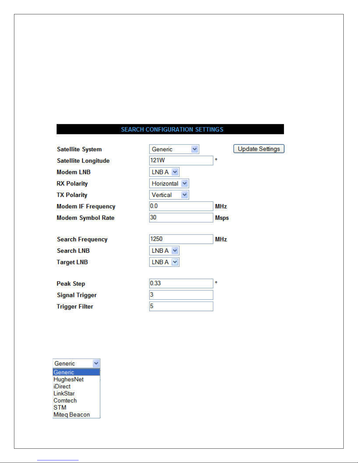
Search Settings Page Page 1 of 2
Config Name (Default)
Satellite System (Generic) Setting required
22
When no modem is connected or does not require
any external input then Generic is recommended.

Satellite System sets Modem or ISP type. Setting this value for the proper
modem type will allow the H3 to integrate at different levels with specific
modems.
Currently the H3 shares data with the Hughes Net and iDirect Modems
allowing the H3 to confirm correct Satellite Identification, Signal Quality
level, set TX ranging values, etc.
Other Modems currently displayed in the Satellite System drop down box
function as Generic mode.
Important Note: It is extremely important that when using Hughes Net
mode that many of the following configurations are set correctly. Just
being close will not work.
Satellite Longitude (121W) Setting required
Satellite Longitude is a numerical value followed by an E or W. This will
set the Default Satellite (Target Satellite) Location. i.e. 121W
The Bandwidth Provider (VAR) will supply the Satellite Longitude
required for the modem to lock to the correct RF carrier.
When inputting a Satellite Longitude in the western hemisphere you
should place a W after the numerical longitude value.
When inputting a Satellite Longitude in the eastern hemisphere you must
place an E after the numerical longitude value.
If you do not place a W or E after the numerical value the hemisphere will
default to West (W).
Modem LNB (LNB A)
The H3 Controller has the ability to search using one LNB and then switch
to a second LNB for proper Modem operation. In most cases all LNB
Search settings should be set to LNB A.
See RF Configuration Settings Page for additional information on how and
when to set up multiple LNB’s.
23

RX Polarity (Horizontal) Setting required
This is a critical setting. The Bandwidth Provider (VAR) will supply the
RX polarization required for the modem to lock to the correct RF carrier.
This will be either H (horizontal) or V (vertical) polarized. This must be
correct for the Modem to operate properly.
TX Polarity (Vertical) Hughes required
Hughes critical setting! The Bandwidth Provider (VAR) will supply the
TX polarization required for the modem to transmit the RF signal in the
correct field.
This will be either H (horizontal) or V (vertical) polarized. This must be
correct for the Modem to operate properly and to not cause RF
interference with other users of the Satellite.
Modem IF Frequency (0) Hughes required
Hughes critical setting! When the Satellite System type is set to
HughesNet (Hughes) you must enter the Receive Frequency (950-2150
MHz) supplied by your Bandwidth Provider in this position.
When not used in Hughes mode this value should normally be set to 0.
Under conditions where a Satellite you are wanting to find (Target
Satellite) is sitting between two stronger satellites (adjacent satellites) it
might be necessary to input an IF frequency that will help you peak on the
Target Satellite without the signals from the adjacent satellites causing the
Dish to pull off and peak onto an adjacent satellite. In this situation a
value other than 0 can be used. See Building a Sat Table for additional
information.
Modem Symbol Rate (30) Hughes required
Hughes critical setting! The Bandwidth Provider (VAR) will supply the
Symbol Rate required for the modem to lock to the correct RF carrier
The symbol rate is entered in Msps (Mega Symbols per Second).
Example; 30,000,000 symbols per second is entered as 30 Msps.
Search Frequency (1250)
24

The Search Frequency is the initial frequency set in the H3 Controller
Tuner to find most Satellite Signals in the sky.
Depending on the general center frequencies of most of the Satellites in
the viewable orbit above your GPS Longitudal position this value can be
changed.
In North America most Ku Band Satellites have a many transponders that
are near 1250 MHz IF. So using 1250 MHz is recommended.
Check Satellite Charts for the particular region in the world you plan to
operate and make changes as needed.
Search LNB (LNB A)
The H3 Controller has the ability to search using one LNB and then switch
to a second LNB for proper Modem operation. Under normal conditions
the Modem LNB, Search LNB, and Target LNB will be set to LNB A.
If the Satellite you are wanting to find is not in the same RF Frequency
band as most of the Satellites in the satellite arc (belt) above, then using
one LNB to search and then switching to another LNB for the Modem to
lock is possible with this setting.
A Dual Band LNB or multiple LNB’s are required for this configuration.
See RF Configuration Settings Page for additional information for
multiple LNB’s or additional Search Paths.
Target LNB (LNB A)
It is possible to set up multiple LNB’s in the H3 Satellite Antenna
Controller to help Search, ID and Lock to the correct Satellite. In certain
conditions the Search and Target LNB may be different for the system to
search correctly.
Peak Step (0.33)
Peak Step is the amount of distance in degrees the Antenna Mount will
move to test the signal level/quality during the peaking routines.
The larger the distance between peak steps could speed up the finished
Peak times but might reduce the accuracy of the peak.
The smaller the peak steps may improve the final signal peak but could
slow down final peak times.
25

Under most conditions 0.33 degrees is a good balance.
Signal Trigger (3)
Signal Trigger is a numerical value that represents a change of Signal
Strength Level during a small period of time. When this value is triggered
the H3 will stop the antenna movement and begin a Signal Identification
Peak.
The Signal Trigger Value is set to Default 5. It can be adjusted from 1 to
50. The lower this value can be set the wider view of the sky for a quicker
search. If this value is set too low the H3 will begin to stop on false
targets such as trees, lights, and buildings. The higher this value is set the
narrower the sky view search angle.
Setting range is 1 to 50.
Trigger Filter (5)
Trigger Filter is the number of consecutive times the Signal Trigger must
see a positive change value before the Antenna Mount will stop to initiate
the peaking routines.
Setting range is 1 to 10.
26
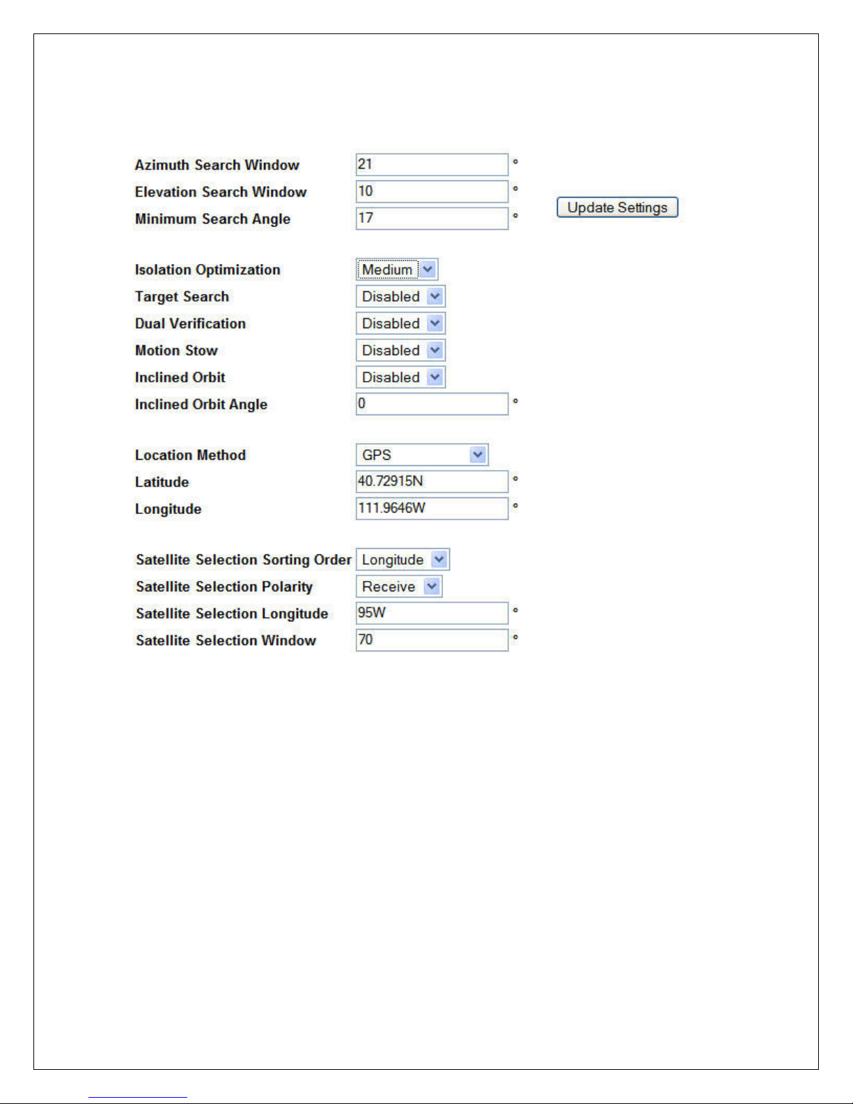
Search Settings Page Page 2 of 2
Config Name (Default)
Azimuth Search Window (21)
The Azimuth Search Window sets the Satellite ID Table size with respect
to the Reference (initial) Satellite Longitude and the Target Satellite
Longitude.
In addition to setting the Sat Table ID size it also sets the maximum search
window in degrees the Azimuth will move in either direction from the
calculated Target Satellite Location.
27

On initial Search the H3 will choose a Satellite Longitude equal to the
GPS Longitude (Reference Satellite). This causes the H3 to search for
Satellites near the top (apogee) of the Satellite Arc.
Setting the Search window narrower will reduce the total number of
Satellites that the Sat Table will ID. This reduces the ID time because the
H3 Controller will not have to test as many Satellite DVB Carriers. The
search times can be reduced if the Satellite Table is built efficiently.
If the Search Window value is set to a larger number this will allow more
Satellites to be identified during the search but will require more ID Time
on every unknown Satellite the system stops on.
Elevation Search Window (10)
The Elevation Search Window is the vertical search area of the Mount
after a Reference Satellite has been located. The H3 will determine the
calculated relative location of the Target Satellite from the Reference
Satellite Location. The H3 will begin a search for the Target Satellite in
the middle of the Elevation Search Window and continue to move the Dish
Elevation higher and lower from this location at the end of every Azimuth
pass until the total value set in this window has been searched. i.e. a value
of 10 in this window will allow the elevation to search 5 degrees above
and below the calculated Target location.
The Default value for Elevation Search Window is 10. This value can be
narrowed if the vehicle is always very level, but not recommended. If the
Mount/Dish is placed on a Skid or Pallet and the ground is not level
increasing this value may be necessary.
Minimum Search Angle (17)
This is the lowest Satellite Look Angle allowed by the H3 Controller when
in search mode. From the factory the H3 is set with an angle of 17
degrees.
Once the Dish is mounted on a roof or platform this value can be changed
as necessary as long as full Azimuth Rotation will not cause the LNB to
hit objects in this rotation. Normally 17 degrees will work for most of the
US and Southern Canada.
Isolation Optimization (Low)
Isolation Optimization is used to set Cross Polarization (Cross Pol) of the
antenna Transmitter to an acceptable Isolation level.
28

Low
When set to Low the skew (polarization) is calculated from the current
GPS readings and the Feed Assembly will rotate the calculated value.
There are no additional adjustments in the Low mode.
Medium
When set to Medium, Skew is initially set using the Low mode routine.
Once the mount is near the correct elevation the H3 will then test the tilt
sensors attached to the mount by rotating the Azimuth 180 degrees to
determine the levelness of the mount. Any offset in level will be added or
subtracted to the GPS calculated value and the Feed Assembly will be
corrected as required.
High
When set to High mode the H3 will first perform the Medium routines.
Once locked onto the Target Satellite the H3 controller will initialize a
signal feedback routine using either the internal DVB Tuner in the H3 or if
using a Hughes modem will initiate an ACP with the Hughes NMC Cross
Pol server.
Note: TX Offset when used will influence the final Skew location. See
TX Offset for additional information.
Target Search (Disabled)
When Target Search is Disabled the H3 Satellite Antenna Controller will
begin an initial search for any/all satellites in the true southern part of the
sky (Longitude Search). During this search the polarization is set to H or
V Field with no skew offset added. Elevation is adjusted to pass through
the highest satellites in the arc. Once a satellite in the Southern part of the
sky has been identified the H3 will correct the Skew for the Target
Satellite and move directly to the calculated position. In most cases, this
search in areas of the world where many satellite can be identified is most
efficient.
When Target Search is Enabled the H3 Satellite Antenna Controller will
calculate the proper Elevation and Skew and begin a direct azimuth search
for the selected satellite (Target). Use this type of search when there are
fewer identifiable satellites in the arc.
Dual Verification (Disabled)
Dual Verification is used in areas where high RF Reflectivity could cause
the H3 to stop and peak on a reflected RF signals. This is normally in an
area with multi-story steel or glass buildings. When Enabled the H3 must
29
verify two satellites in the proper orbital locations before completing the
Location Method allows a more flexible setup of
Search Operation.
Note: With Dual Verification Enabled it is recommended to Enable
Target Search also.
Motion Stow (Disabled)
Motion Stow is initiated when the Tilt (accelerometer) Sensors detect
motion other than mild rocking caused by wind. The H3 Controller must
be powered ON for Motion Stow to work.
Note: Some vehicles may disable the AC power when the ignition has
been turned ON. If the DC Power Supply that runs the H3 is on this AC
Power circuit then Motion Stow will not work.
Inclined Orbit (Disabled)
Inclined Orbit is used when the Target Satellite is constantly moving in a
Vertical Elevation pattern from the determined Clark Orbital slot. To
track this kind of Satellite this configuration must be Enabled.
This mode could also be used in areas where a mount is placed on an
unstable surface such as snow or mud and minimal mount adjustments
may be required.
This routine CAN NOT be used for a vehicle or platform in motion.
Inclined Orbit Angle ( 0 )
The Inclined Orbit Angle is set when the Vertical Change of an Inclined
Orbit Satellite is known.
Inclined Orbit Satellites usually change less than +/- 6 degrees in a vertical
direction. There is a small amount of Azimuth deviation on an Inclined
Orbit Satellite which is also tracked when Inclined Orbit is Enabled.
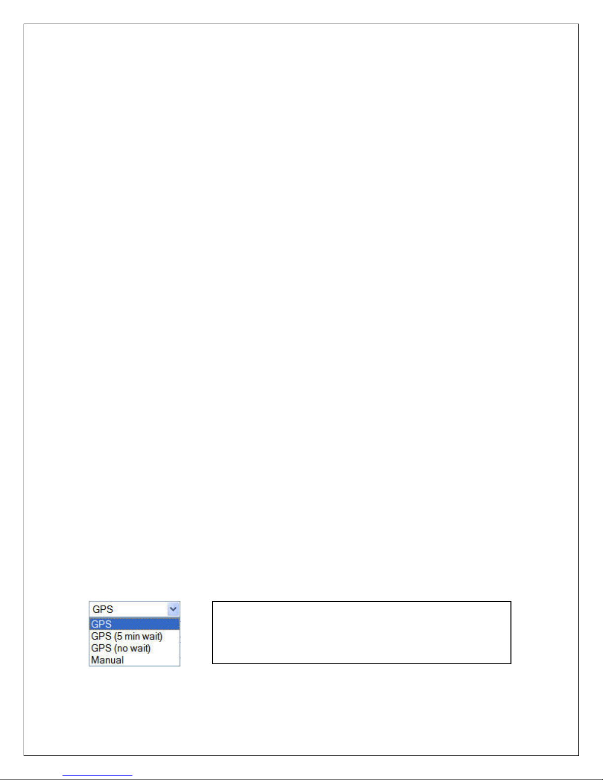
Location Method (GPS)
GPS requirements depending on the users needs.
Please study the options below to determine what
fits the user application best.
GPS
30
 Loading...