

MotorVac MCS 245 User Manual

Fuel System Service &
Diagnostic Equipment
OPERATOR’S MANUAL
MCS 245
PDF VERSION

Table of Contents
Introduction .............................................................................................. Error! Bookmark not defined.
Overview ................................................................................................... Error! Bookmark not defined.
System Features and Functions ......................................................................................................1-1
System Features and Functions....................................................................................................1-2
Hose and Battery Connections......................................................................................................1-3
Fuel Filter.......................................................................................................................................1-5
Theory of Operation………………………………………………………………………………………1-6
Safety Information .............................................................................................................................2-1
Before You Begin...............................................................................................................................3-1
First Time Operation......................................................................................................................3-1
Mixing Ratio...................................................................................................................................3-2
Fuel System Cleaning Procedures...................................................................................................4-1
Determining the Vehicle's Fuel System Type................................................................................4-1
Carburetor Setup Procedure .........................................................................................................4-3
Carburetor Cleaning Procedure ....................................................................................................4-7
Throttle Body Injection (TBI) Setup Procedure .............................................................................4-9
Throttle Body Injection (TBI) Cleaning Procedure.......................................................................4-13
Port Fuel Injection (PFI) Setup Procedure ..................................................................................4-15
Port Fuel Injection (PFI) Cleaning Procedure .............................................................................4-19
Continuous Injection System (CIS) Setup Procedure .................................................................4-21
Continuous Injection System (CIS) Cleaning Procedure ............................................................4-25
Returnless System Setup Procedure ..........................................................................................4-27
Returnless System Cleaning Procedure .....................................................................................4-29
Vehicle Diagnostics ...........................................................................................................................5-1
Fuel System Pressure Test ...........................................................................................................5-2
Fuel Volume Test ..........................................................................................................................5-3
Deadhead Test ..............................................................................................................................5-4
Leakdown Test ..............................................................................................................................5-5
Vacuum Pressure Test ..................................................................................................................5-6
Intake System Cleaning Procedures................................................................................................6-1
Troubleshooting and Additional Help..............................................................................................7-1
Appendix A - Maintenance............................................................................................................... A-1
Maintenance Procedures ............................................................................................................. A-1
Replacing the Fuel Filter .............................................................................................................. A-1
Maintenance Record .................................................................................................................... A-2
Appendix B - System Accessories..................................................................................................B-1
Standard Adaptor Kit .................................................................................................................... B-1
Deluxe Adaptor Kit........................................................................................................................ B-5
Optional Adaptors Available ........................................................................................................ B-9
Appendix C - Parts............................................................................................................................C-1
Service Parts ............................................................................................................................... C-1
Appendix D - MATERIAL SAFETY DATA SHEET........................................................................... D-1
Material Safety Data Sheet ................................................................................................................. D-1
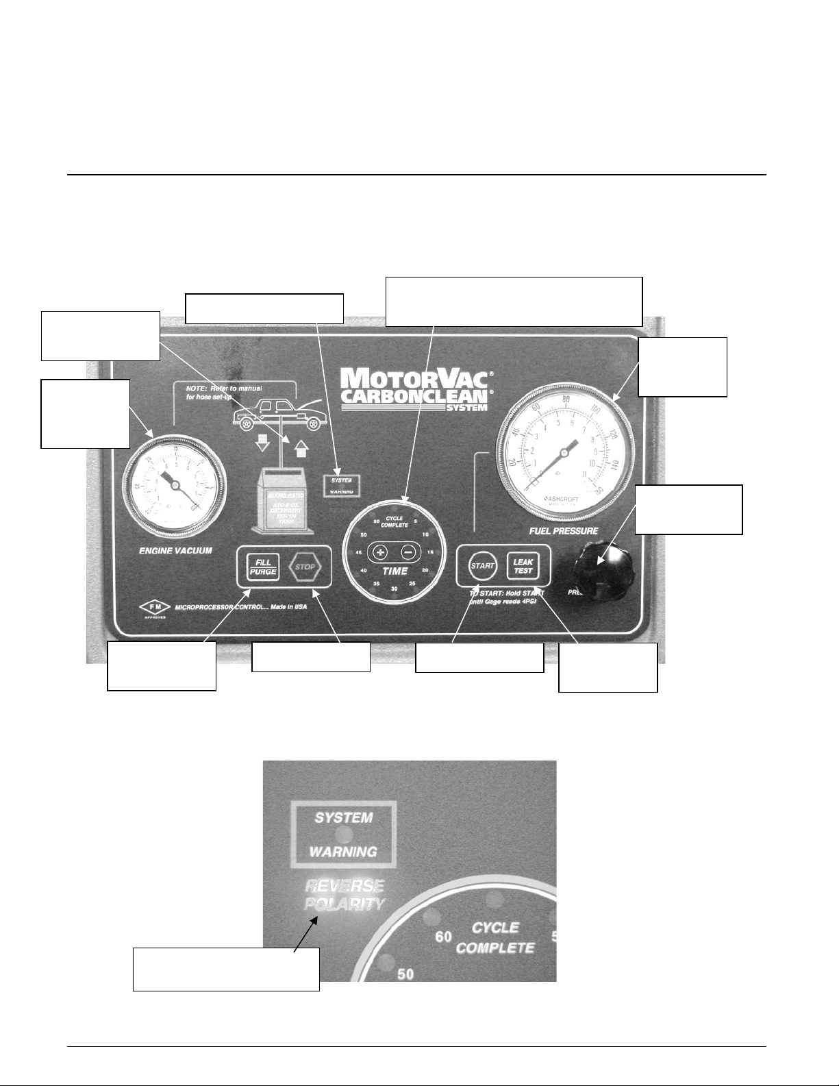
System Features and Functions
The front of the MotorVac CarbonClean System cabinet contains a software-driven control panel, the opening
for the fuel reservoir, and storage drawers for adaptors and other system accessories.
UP / DOWN
ARROWS
ENGINE
VACUUM
GAUGE
FILL / PURGE
BUTTON
SYSTEM WARNING
STOP BUTTON
TIME DISPLAY, CYCLE COMPLETE
LED & TIMER BUTTONS
START BUTTON
LEAK TEST
BUTTON
FUEL
PRESSURE
GAUGE
PRESSURE
REGULATOR
REVERSE POLARITY
LED

System Features and Functions
Descriptions of the gauges, control buttons, and LED indicators that make up the control panel are listed below.
Please become familiar with these control panel features and functions before using the unit
Stop Button
Fill/Purge Button
Engine Vacuum Gauge
Reverse Polarity LED
Down Arrow LED
Up Arrow LED
System Warning LED
Warning Alarm
Fuel Level Window
Cycle Complete LED
Fuel Pressure Gauge
Start Button
Pressure Adjust Regulator
Leak Test Button
Timer Buttons
Time LED
Allows the increasing or decreasing of time on the timer. The button
Stops all run conditions.
Fill: Transfers fuel from the fuel tank of the vehicle being serviced to the
unit’s reservoir. Purge: Relieves fuel lines of remaining pressure by
transferring fuel back into the unit’s reservoir.
Displays vacuum pressure on the vehicle being serviced.
Illuminates when:
• Polarity is reversed on the connection between the vehicle battery and
the
unit.
Illuminates when the fill/purge process is under way.
Illuminates when the service is under way.
Illuminates when:
• The fuel/detergent mixture runs out before run time expires.
• Vehicle or unit pressure drop (less than 5psi) is detected.
Sounds when the service is complete, or when the vehicle or unit’s pressure
drops below 5psi.
To view the amount of fuel/detergent mixture remaining in the unit’s
reservoir.
Illuminates when the service ends.
Displays output pressure of the unit’s output hose, or system pressure of the
vehicle being serviced.
Begins the service.
Used to adjust the system pressure during the cleaning process. Turn
clockwise to close (increase the pressure); counterclockwise to open
(decrease the pressure).
Begins the Leak Test.
increases the time, and the
A circle of LEDs displaying the time in five-minute increments.
▬ button decreases the time.
.
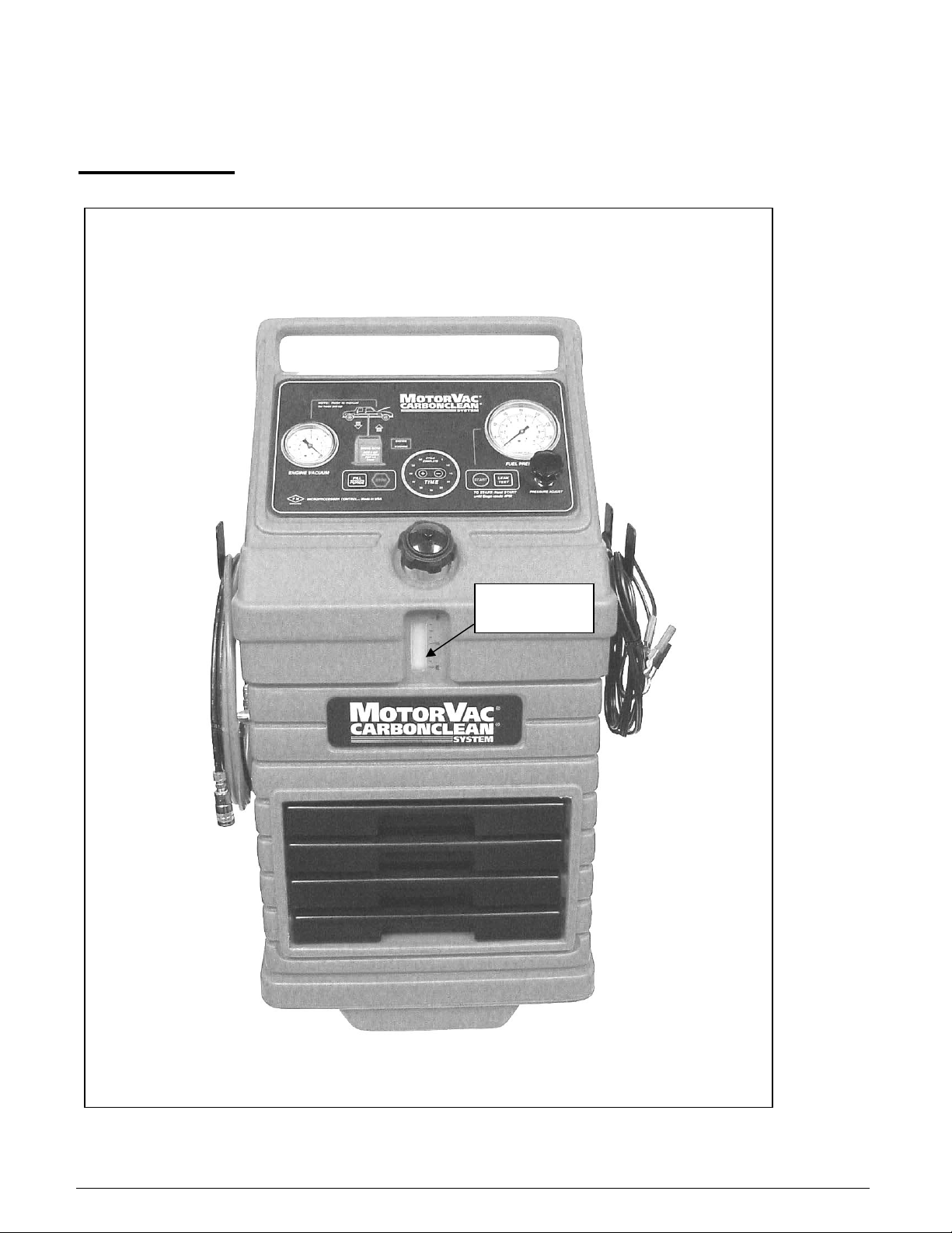
FRONT VIEW
FUEL LEVEL
WINDOW

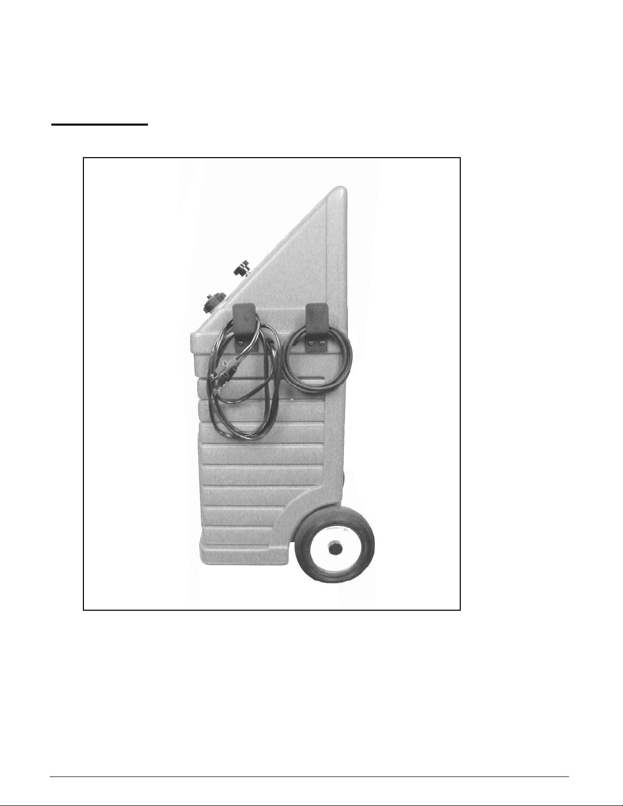
LEFT VIEW
As you face the system, the left side of the unit’s cabinet holds the fuel return and output hoses, while the right
side of the unit’s cabinet holds the battery cables and vacuum pressure hose.
Output Hose (red)
Return Hose (black)
Quick Couplers
Connects to the input side of the vehicle's engine fuel system.
Connects to the return side of the vehicle's engine fuel system.
Secures the unit’s
engine fuel system.
return/output hose connections to the vehicle's
RIGHT VIEW
Vacuum Hose
Battery Cables
Forms a connection between the vacuum pressure from the vehicle
engine and the vacuum pressure gauge on the unit.
Positive (red) and negative (black) battery connections (12-16
VOLTS DC and 8 AMPERES)
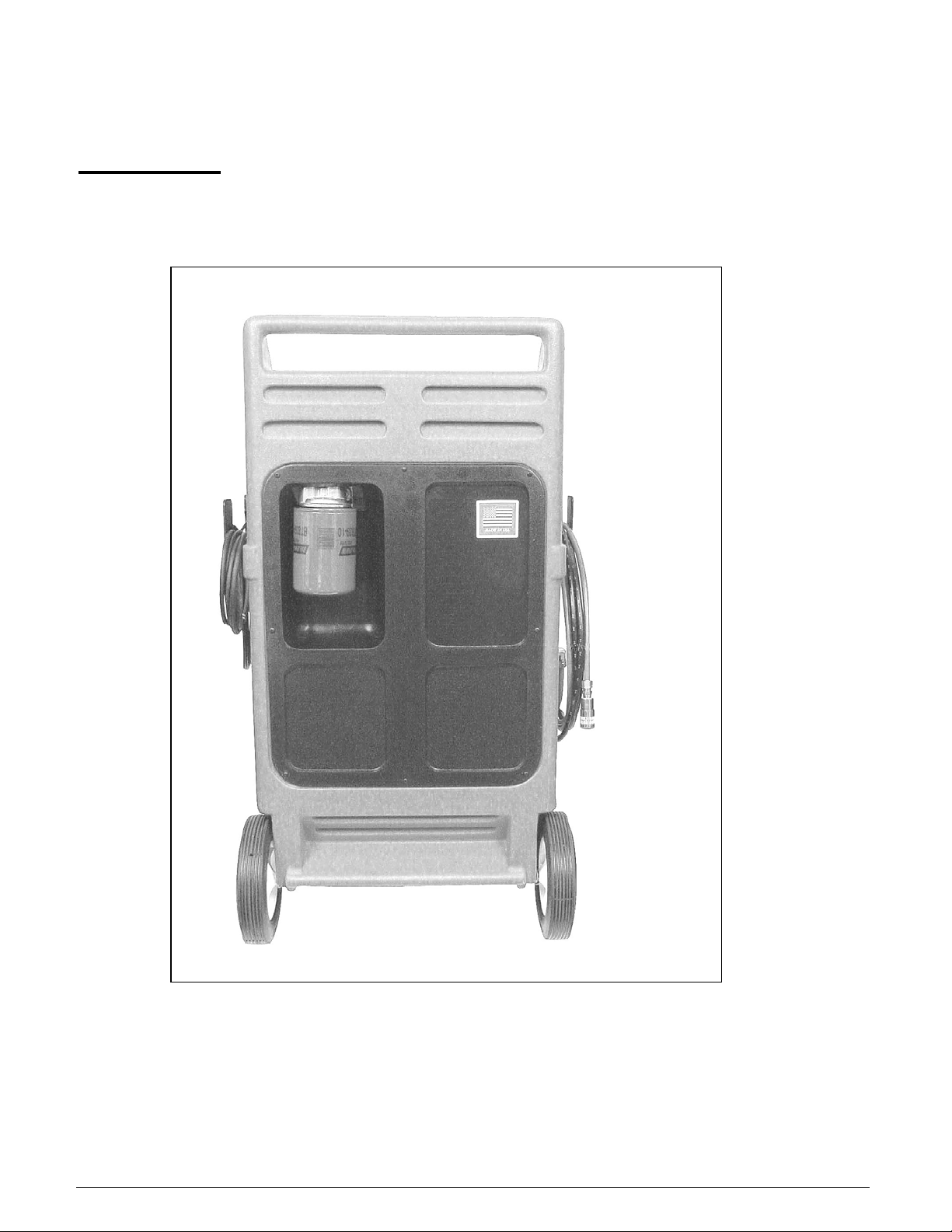
BACK VIEW
The back of the unit’s cabinet contains an easy access area for the fuel filter, along with storage slots for shop
towels, detergent bottles, etc. Please see
Appendix A for information on replacing the unit’s fuel filter.

Theory of Operations
Detailed descriptions of the various operations, control buttons, and LED indicators are listed below.
Fill Operation:
• Press and Hold the FILL/PURGE button. This opens the solenoid and starts the pump motor in the Fill/Purge
direction. Releasing the button stops the motor and closes the solenoid.
• Whenever the motor is pumping in the Fill/Purge mode, the DOWN ARROW LED (Pointing down away from
the picture of the car on the panel) is on.
Cleaning (Service) Operation:
• Press and hold the START button. This opens the solenoid and starts the pump motor in the Service direction
• Release the START button after the pressure gauge reads at least 5 PSI. The pump will continue to run and
TIME LED will display time remaining.
• When the run time is complete, the pump motor stops and warning beeper will sound for 6 seconds. One
second after the pump motor stops, the pump motor will start and run in the purge mode (reverse) direction for
5 seconds. The solenoid remains open during the purge mode. When the purge is complete, the pump motor
stops and the solenoid closes.
• If the pressure drops below 4 PSI while the engine is running, or the START button is released before the
pressure reaches 4 PSI, the motor will stop for one second, then run in the purge mode (reverse direction) for 5
seconds with the solenoid open. When the purge is complete, the pump motor stops and the solenoid closes.
• Whenever the unit’s motor is pumping in the clean mode the UP ARROW LED (Pointing up towards the
picture of the car on the panel) is on. This LED will blink while the pressure switch is open (less than 4 PSI)
and stays on solid when the pressure switch is closed (greater than 4 PSI).
Leak Test Operation:
• While in the service mode, press and release the LEAK TEST button. The solenoid will close and the TIME
LED will show the leak test time remaining.
• During the leak test, only the TIME LED display will be on.
• To end the leak test mode and begin the cleaning service, press the start button.
• To end the leak test mode, press and release the STOP button. This will open the solenoid and begin the purge
mode.

Pressure Switch Operation:
• The pressure switch is opened when the pressure is less than 4 PSI and is closed when the pressure is 4 PSI or
greater.
• The internal pressure switch is not adjustable.
Solenoid Operation:
• The solenoid opens when the pump motor is running in either fill/purge or cleaning (service) mode. Note: The
solenoid is normally closed.
Stop Operation:
• Whenever the STOP button is pressed, the unit’s pump motor will stop and TIME LED display is turned off.
The unit will automatically go into purge mode.
Timer Operation:
• LED will blink in five-minute increments. For example, if 12 minutes are left in the run cycle, the 15-minute
LED will flash until the timer reaches 10 minutes.
• When the timer reaches 0 minutes left, the CYCLE COMPETE LED will go on and the end of service alarm
will sound.
Service Time Operation:
• The TIME and the
progress.
• The maximum time available is 60 minutes; the minimum time available is 5 minutes. The time is adjusted in
increments of 5 minutes. There is a 10-minute increment between 50 and 60 minutes, so a time of 55 minutes
cannot be set.
• When the timer starts, the time can be adjusted. The first minute after setting the timer, the unit will check to
see if the time has changed. If it has, this new time will be stored as the cycle time for the current run. This
applies to cleaning and leak test times.
• If the
• When the unit is powered on, the CYCLE COMPLETE LED is displayed.
▬ button is continuously pressed until the time reaches zero, the end of service alarm will sound and
the CYCLE COMPLETE LED will turn on.
▬ buttons are used to adjust the service time, while the cleaning or leak test is in
Fuel Level Window Operation:
• The FUEL LEVEL WINDOW shows the amount of fuel in the tank.
• The FUEL LEVEL WINDOW indicates the fuel level in 1/8-tank increments. From the empty to the full mark
is approximately one gallon.
• When the FUEL LEVEL WINDOW is at the empty (“E”) level there is approximately one and a half quarts of
fuel in reserve below the reservoir empty level, in the filter, pump, tank, and lines.

Safety Information and Precautions
/!\ DANGER
Vehicle exhaust gases contain Carbon Monoxide, which is a colorless and odorless lethal gas.
Only run engines in well-ventilated areas and avoid breathing exhaust gases.
Extended breathing of exhaust gases will cause serious injury or death.
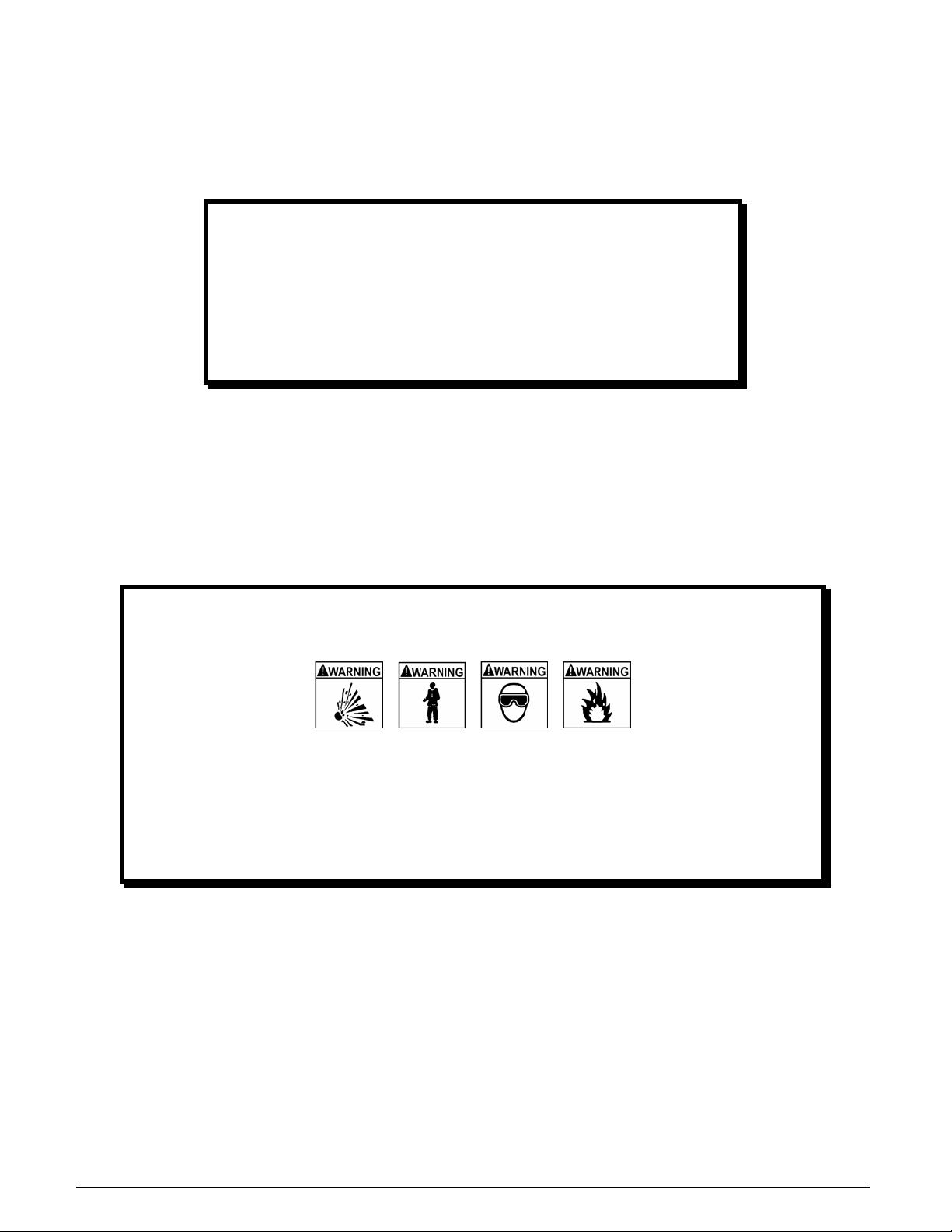
/!\ WARNING
Exhaust gases, moving parts, hot surfaces, and potent chemicals are present during the use of the fuel system
cleaner.
Read and understand the operator’s manual before using the fuel system cleaner.
When using chemicals always refer to the MSDS sheets and manufacturer’s instructions for the proper
procedure to handle emergency medical treatment, cleanup, handling, and storage requirements.
Improper use of the fuel system cleaner or exposure to exhaust gases or cleaning chemicals can cause injury.
Flammable fuel chemical and vapors can ignite.
Avoid exposure to flames, sparks, hot engine parts, and other ignition sources.
Always keep fully charge fire extinguisher nearby. The extinguisher should have a class B rating and be
suitable for gasoline, chemical, and electrical fires.
Cleanup any fuel or chemical spills immediately.
Dispose of contaminated cleanup material according to governing environmental laws.
Never look directly into the air induction plenum or carburetor throat when the engine is operating.
Always plug or cap any open fuel lines during service.
Keep Cleaner and Detergent container closed except when filling reservoir.
Explosion or flame or exposure to flammable liquid and vapors can cause injury.
Flammable liquid can splash out of reservoir when pump is on and/or unit is being moved.
Always keep Reservoir Cap secure except when filling reservoir.
Explosion or flame can cause injury.
Many fuel systems maintain residual pressure in fuel lines even after the engine has been turned off.
Wear safety goggles.
Wear chemical resistant gloves when connecting or disconnecting fitting and adaptors.
Obtain ZERO psi before connecting or disconnecting any fuel lines or adaptors.
Explosion or flame or exposure to flammable liquid and vapors can cause injury.
Chemicals can cause harmful byproducts.
Use only approved chemicals (refer to operator’s manual).
Do not swallow or ingest any chemicals.
Use with adequate ventilation. Avoid breathing vapors.
Do not store chemicals on the machine.
Improper use of chemicals can cause injury.
Over exposure can have harmful effect on eyes, skin, respiratory system and possible unconsciousness and
asphyxiation.
Improperly blocked vehicles can move.
Set the parking brake and chock the wheels.

Moving vehicles can cause injury.
Moving engine parts.
The engine cooling fan will cycle on and off depending on the coolant temperature and could operate without the
engine running.
Wear safety goggles.
Always keep objects, clothing, and hands away from the cooling fans and engine parts.
Moving engine parts can cause injury.
Hot surfaces are present during and after running the engine.
Do not contact hot surfaces such as, manifolds, pipes, mufflers, catalytic converters, or radiators and
hoses.
Hot surfaces can cause injury.
Catalytic converters become extremely hot.
Do not park a converter-equipped vehicle over dry grass, leaves, paper, or any other flammable material.
Do not touch a catalytic converter until the engine has been off for at least 45 minutes.
For tests allowing unburned hydrocarbons or service involving operation of an overly rich condition,
minimize the time of rich operation, monitor the catalytic converter temperature, and allow at least two
minutes of operation at normal mixture subsequent to testing or service for converter cooling.
Catalytic converters can cause burns.
Cracked fan blade can become airborne.
Examine fan blades for cracks. If found, do not service the vehicle.
Flying objects can cause injury.
Batteries produce explosive gases and can explode.
Wear safety goggles when working on or near batteries.
Use in a well-ventilated area.
Keep sparks and flames away from the battery and never lay tools, equipment, or other conductive objects
on the battery.
When tools or equipment is connected to the battery, make sure the equipment power switch is off.
Connect the positive lead of the equipment to the positive lead battery first; connect the negative lead of
the equipment to a solid ground point as far from the battery as possible.
Keep battery acid away from skin or eyes. In case of eye contact, flush with clean water for 15 minutes
and get medical attention.
Battery explosion and ignited gases can cause injury.
Before You Begin
First Time Operation
NOTE
The following process is used to flush factory testing fluids out
of your new machine, and is only necessary before the first
time you use the unit.
Remember to send in your warranty card to properly register
your machine.
1.
2.
3. Turn the Pressure Adjust regulator on the unit control panel counterclockwise until it is completely
4. Attach the unit to a motor vehicle battery by connecting the red battery clip to the positive (+) battery
5.
6. Connect the unit’s output (red) hose and return (black) hose together by using the
#060-1100 and #060-1400 adaptors and securing them with a clamp. Follow the procedures below to
7. Disconnect the output and return lines.
8.
Verify that the unit’s fuel filter is connected and securely in place on the filter base assembly at the rear of
the cabinet
Check the output/return hoses, battery connections, and all external components for damage.
open.
terminal and connect the black battery clip to a solid ground point as far from the battery as possible.
Fill the unit’s reservoir with clean gasoline until the Fuel Level Window indicates 1/4 tank.
flush fuel through the system:
• Press and hold
• Release the Start button.
Connect the #060-1100 adaptor to the (red) output hose. To flush the gasoline from the unit’s reservoir
using the following procedure:
• Direct the adaptor on the (red) output hose into an appropriate container.
• Press and hold
• Release the Start button.
• Dispose of the fuel in an environmentally approved method.
.
the Start button for five minutes. This will thoroughly flush the system with clean
gasoline.
the Start button until the unit’s reservoir is empty.

9. The unit’s reservoir is now completely drained of fuel. Follow the steps below before performing the first
cleaning service:
• If necessary, Repeat Steps 3-4 from the previous page.
• Pour 20 oz. of detergent to the unit’s reservoir.
• Add clean gasoline to the unit’s fuel reservoir until the mixture of fuel and detergent reaches 1/4 tank
according to the Fuel Level Window.
• The unit
is now ready to perform a cleaning service.
NOTE: When adding detergent to reservoir, pour in the 8oz. bottle of detergent first. For each 8oz. bottle, bring fuel level to ¼
level. When tank is at zero, add four 8oz bottles of detergent first, then fill reservoir to top with fuel. From the empty level to
the full level is approximately one gallon.
Fuel System Cleaning Procedures
Determining the Vehicle's Fuel System Type
It is very important to determine the fuel system type of the vehicle to be serviced before performing any setup or cleaning
procedure on the vehicle. The unit can be used with any of the four different types of fuel systems listed below:
Carburetion
Carburetors come in a variety of sizes and shapes. Locating the choke plate in the air horn can
easily identify these.
Throttle Body Injection (TBI)
Throttle bodies are centrally mounted, as are carburetors, and use one or two electronic injectors
mounted in the throttle body.
Port Fuel Injection (PFI)
This system uses one electronic injector per cylinder, mounted so that fuel spray is directed into
the intake port.
Continuous Injection System (CIS)
Noting the fuel distributor and the solid steel or flex steel lines running from the fuel distributor to
each individual injector easily identifies a Continuous Injection System. The fuel distributor
controls the amount of fuel sprayed into the intake port while the injectors control the opening and
closing pressure.
Returnless Injection System
Returnless fuel systems are similar to Port Fuel Injection systems with a few exceptions.
Returnless systems do not have a pressure regulator on the fuel rail & do not use a fuel return line
leading back to the fuel tank. Because these systems do not control pressure at the rail assembly
(Pressure is regulated inside the fuel tank) and do not have a provision for a return line
connection, the rail flush procedure is not performed. Refer to the Returnless fuel section for
specific procedures.
Once you have determined the fuel system type, turn to
the appropriate section in this chapter for instructions on
how to perform the fuel line setup and cleaning procedure
for that system.
NOTE

Carburetor Setup Procedure
Follow the steps below to connect the unit to the vehicle's fuel system in order to obtain fuel from the vehicle for use during
the cleaning procedure. Make sure the vehicle has at least 1/8 tank of fuel before beginning this process.
Start the vehicle and allow the engine to reach normal operating temperature.
1.
IMPORTANT
Do not perform the setup or cleaning process if the
vehicle’s engine oil or coolant level is low. If necessary,
add oil and/or coolant to the vehicle.
2. Turn the vehicle OFF when normal operating temperature has been reached.
3.
Turn the Pressure Adjust regulator counterclockwise until the regulator is completely open.
4. Attach the unit to the vehicle's battery by connecting the red battery clip to the positive ()
Battery terminal and the
possible.
If the
battery are correct as described above.
5. Loosen the vehicle's gas cap to relieve fuel tank pressure, and then re-install cap.
6. Verify that the engine is no longer running.
7. Disconnect the vehicle’s fuel line at the carburetor inlet or at the fuel pump outlet.
There should now be two open ends to work with:
• one coming from the fuel pump.
• the other going into the carburetor.
black battery clip to a solid ground point as far from the battery as
Reverse Polarity LED comes on, make sure the connections to the vehicle's
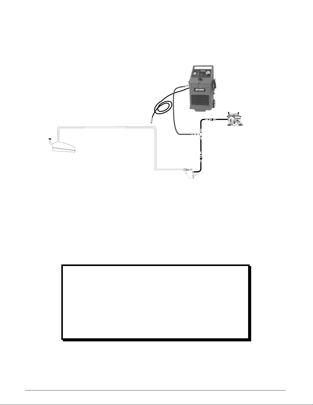
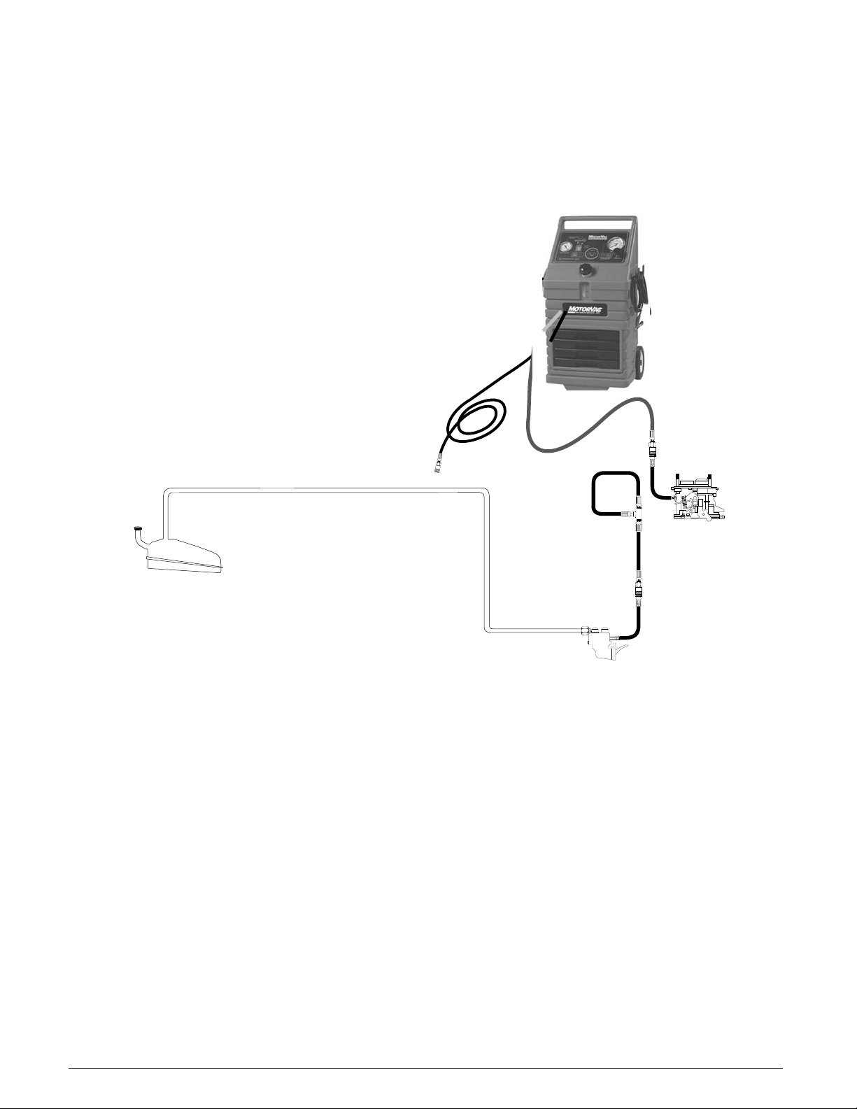
8. As shown below, connect the appropriate adaptors at the two points listed in Step 7.
FUEL TANK
RED HOSE
FUEL PUMP
ADAPTOR
060-4500 " T "
ADAPTOR
CARBURETOR
PRESSURE LINE
BLACK HOSE
➩➩➩
9.
As shown in the previous figure, attach the ends of the T-adaptor (#060-4500) to both
adaptors, and then attach the output (
adaptor. The return (
black) hose on the unit is not used at this time.
red) hose to the center connection on the T-
. Start the vehicle's engine and check all connections for leaks. Make a note of the
10
Fuel Pressure gauge on the unit to test system pressure, since pressure loss can
indicate a leak.
DIAGNOSTICS
The vehicle’s fuel system is now prepared to perform
diagnostic tests if desired. For instructions on how to
perform these tests, go to the next chapter titled Vehicle
Diagnostics.
If vehicle diagnostics are not desired, continue the cleaning
procedure beginning with Step 11 below.
11. When filling the reservoir, add 8 oz. of detergent first for every 1/4 tank of fuel added.
12. Press and hold the Fill/Purge button on the control panel until the Fuel Level Window indicates a
combined increase of 1/4 tank in the unit’s fuel reservoir.
NOTE
If the vehicle’s engine stalls, restrict pressure in the fuel
line by turning the gate valve on the T-adaptor (#060-
4500) clockwise 1/4 turn. Re-start the car and repeat
Step 12. If the vehicle’s engine stalls again, repeat this
procedure until Step 12 is completed.
13.
Turn off the vehicle's engine.
Verify the Pressure Adjust regulator on the unit is completely open.
14.
15. Press and hold the Fill/Purge button for five seconds. This will relieve pressure in the
output (
red) hose. Release the Fill/Purge button.
/!\ WARNING
Flammable Liquid can squirt out of pressurized lines when connecting or disconnecting.
Wear Safety goggles.
Obtain ZERO pressure before connecting or disconnecting any fuel lines or adaptors.
Wear chemical resistant gloves when connecting or disconnecting fittings and adaptors.
Wrap shop towel around pressure fittings and adaptors when disconnecting.
Avoid exposure to flames, sparks, hot engine parts, and other ignition sources.
Explosion or flame or exposure to flammable liquid and vapors can cause injury.
Close the gate valve on the T-adaptor (#060-4500), and then carefully remove the output (red) hose from
16.
the T-adaptor (#060-4500).
17. As shown in the next figure, disconnect the female end of the T-adaptor (#060-4500)
from the carburetor and connect it to itself at the male fitting. This stops the flow of
fuel from the vehicle to the carburetor during the cleaning process.
FUEL TANK
PRESSURE LINE
➩➩➩
BLACK HOSE
RED HOSE
ADAPTOR
060-4500 " T "
CARBURETOR
ADAPTOR
18.
As shown in the previous figure, connect the output (red) hose from the unit to the
adaptor going into the carburetor.
You are now ready to perform the carburetor cleaning procedure.

Carburetor Cleaning Procedure
Follow the steps below to circulate the fuel/detergent mixture through the vehicle's carburetor.
1.
Verify that Carburetor Setup Steps 1-18 above have been completed.
2. Refer to the vehicle's service manual for the manufacturer's recommended PSI.
• At this point, refer to appropriate Intake System Cleaning Procedure section for proper intake
cleaning, and Vacuum gauge connections in the vehicle diagnostics chapter.
3. Press and hold the Start button.
Turn the Pressure Adjust regulator clockwise until the Fuel Pressure gauge reads 4
4.
or the equivalent of the manufacturer's recommended specifications. It may be
PSI,
necessary to increase the pressure to the level previously noted in
Carburetor Setup Procedure.
Release the Start button.
5.
Press the button to increase the time, or the ▬ button to decrease the time until the
6.
Time LED displays 30 minutes. (Run time may be adjusted depending on the
condition of the vehicle’s fuel system.)
7. Start the vehicle to begin the fuel system cleaning process.
• When the cleaning process is halfway completed (check
accelerator quickly three or four times.
Then, maintain RPM at 1500 - 2000 for 30 seconds.
8. When the run time expires, the cleaning is complete. The unit will automatically shut
off and purge the pressure lines for five seconds. The
control panel will illuminate, and the unit’s alarm will sound.
9.
Turn OFF the vehicle's ignition.
Turn the Pressure Adjust regulator counterclockwise on the unit to open it. Press
10.
and hold the
red) hose. Release the Fill/Purge button.
(
Fill/Purge button for four seconds to relieve pressure from the output
11. Loosen the vehicle's gas cap to relieve fuel tank pressure, and then re-install cap.
Time LED display), step on the vehicle’s
Cycle Complete LED on the
Step 10 of the

IMPORTANT
Wrap a shop towel around pressure fittings before
disconnection to protect against residual fuel spray.
12. Disconnect the battery leads, hoses, and adaptors. Return the vehicle's fuel
system to its normal operating condition by re-connecting the vehicle's fuel lines.
Start the vehicle and verify that there are no leaks.
13.
14. Test drive the vehicle for three miles immediately following the cleaning service to
flush all detergent from the vehicle's fuel and exhaust systems.
 Loading...