

MotorVac COOLANTCLEAN III User Manual

MOTORVAC
TECHNOLOGIES INC.
COOLANTCLEAN
III
Engine Cooling System Service
MANUAL #200-8232PL
Operator’s Manual

Table of Contents
Introduction…………………………………………………………………………………………….………3
Overview………………………………………………………………………………………………………...4
System Features and Functions……………………………………………………………………...…..1-1
Control Panel Features and Functions………………………………………………………………...1-1
Left View…………………………………………………………………………………………………..1-2
Right View…………………………………………………………………………………………………1-3
Theory of Operation……………………………………………………………………………………...1-4
Safety Information…………………………………………………………………………………………...2-1
Before You Begin…………………………………………………………………………………………….3-1
First Time Operation..................................................................................................................... 3-1
Cooling System Service Procedure ................................................................................................4-1
Troubleshooting and Additional Help.............................................................................................5-1
Appendix A - Maintenance ...............................................................................................................A-1
Maintenance Procedures.............................................................................................................. A-1
Replacing the Unit’s Filter. …………………………………………………………………. ............. . A-1
Maintenance Record ....................................................................................................................A-2
Appendix B - System Accessories..................................................................................................B-1
Included Adaptors………………………………………………………………………………..………B-1
Optional Adaptors………………………………………………………………………………..………B-2
Appendix C - Parts ............................................................................................................................C-1
Service Parts. C-1
Ordering Parts……………………………………………………………………………………………C-1

Introduction
Congratulations on your selection of the CoolantClean3 Cooling System Service Unit.
By choosing this product, you are acquiring the most technologically advanced method
available for performing cooling system services and coolant exchanges.
The CoolantClean3 System is designed to service most automotive applications by exchanging virtually
All of the coolant in the vehicle’s cooling system. Connections to the vehicle are achieved with the
supplied adaptors that install in-line between the vehicle’s radiator & upper radiator hose.
Once connected, the unit can be safely used to:
Relieve system pressure to provide safe, worry-free access to the vehicle’s system.
Pull down or evacuate the coolant levels in the radiator and overflow tanks,
providing safe connection of the unit without hot coolant worries.
Service the cooling systems by exchanging the coolant in the vehicle’s system.
With the vehicle’s engine idling, the CoolantClean3 unit receives used coolant flow from the vehicle’s
system through its RED hose and diverts the flow to an external waste container or to the shop’s coolant
disposal system. At the same time, new coolant flow to the vehicle will be supplied from the
CoolantClean3’s pump through the Green hose. When complete, the unit will automatically revert to a
bypass or flow through mode alleviating the need to watch over the service.
It is recommended that vehicles (with conventional type coolant) have their cooling systems serviced
every 15,000 to 30,000 miles, or according to the manufacturer’s recommendations. Periodic service
intervals are recommended to provide proper protection against overheating and breakdown of the
coolant’s protective properties. Old coolant can no longer protect against rust or acids that can
breakdown metal & aluminum parts in the system.
Have all associated personnel study this Operators Manual completely to become thoroughly familiar
the CoolantClean3 Cooling System Service Unit & it’s proper operation.
IMPORTANT
The CoolantClean3 Cooling System Service is designed to work
EXCLUSIVELY
With standard automotive coolant formulations.
Use of additives or chemicals during services may cause operational failure of
the CoolantClean3 Service System and will void the manufacturer’s warranty.
See the warranty card for specific details.

Overview
This manual contains all the information you need to use the CoolantClean3 Service Equipment. Please
make sure all technicians using the unit & performing services read this manual and have it within easy
reach whenever the unit is being used.
The following is a quick reference to the information in this manual.
System Features and Functions
This chapter describes the CoolantClean3 Service System’s Controls, Switches, Lights,
Connections and their proper usage.
Safety Information
Read & adhere to the safety guidelines in this chapter at all times!
Before You Begin
Follow the instructions in this chapter to prime the unit & check operation before using
the CoolantClean3 unit for the first time.
Service Procedure
This chapter contains a step-by-step setup and service procedures for:
Relieving system pressure
Evacuating coolant in the radiator or overflow tank
Performing a cooling system service.
Troubleshooting and Additional Help
Turn to this chapter in the unlikely event you have problems with your
CoolantClean3 service equipment or need additional help.
Appendices - Maintenance, Accessories, and Parts
The appendices contain routine maintenance procedures for the CoolantClean3 such as
replacing the filter, lists of any available accessories & replacement parts.
System Features and Functions
The front of the Coolant Clean-III Cooling System Service unit contains the Control Panel,
Fluid Filler Neck for adding coolant to the unit’s Reservoir Tank & Tank Level Indicator.
System overview and descriptions follow.
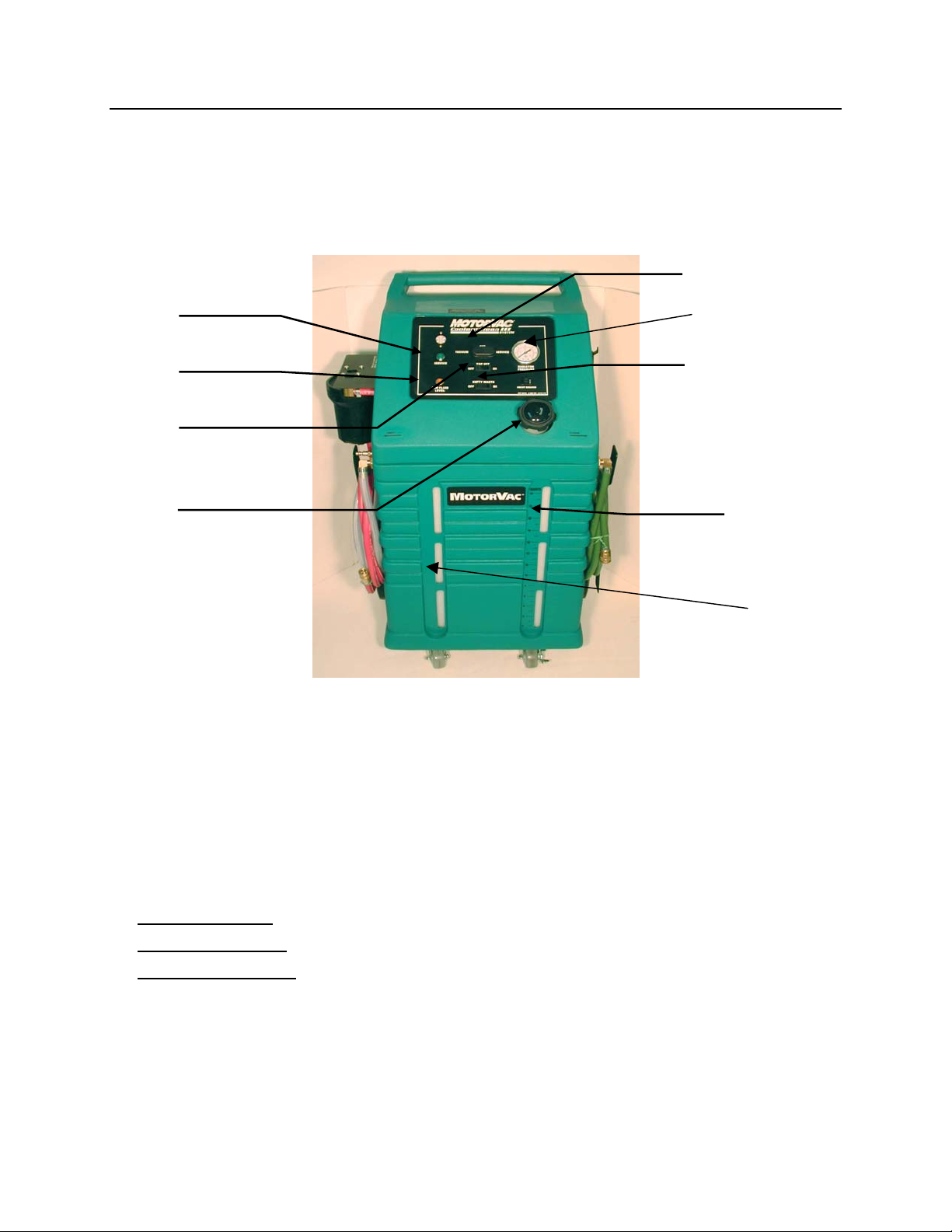
Front View - Control Panel Features and Functions
D.
E.
C.
B.
A
A. Reservoir Filler Neck
B. Top-Off Switch
C. Amber “Low Fluid Level”
Indicator Light
F.
G.
H
Access port to add coolant mixture to the unit’s reservoir tank.
Used to Top-Off / add coolant to the vehicle’s system.
Upon completion of the service procedure.
Illuminates when the unit’s reservoir tank has been depleted of
coolant.
D. Green “Service in
Progress”
Indicator Light
E. 3 Position Power Switch:
CENTER Position:
PRESSED TO LEFT:
PRESSED TO RIGHT:
F. Empty Waste Switch
G. Clean Tank Level Indicator
H. Waste tank level indicator
I. Output pressure gauge
Illuminates when the unit is in the SERVICE mode
Unit will be OFF / In By-pass mode (when connected to a vehicle)
Activates the unit’s VACUUM mode
Activates the unit’s SERVICE mode
Used to empty the waste from ‘capture’ tank after service is
completed.
Indicates the coolant mixture level in unit’s reservoir tank.
Indicates the used fluid level in the capture tank.
Indicates system pressure during service.
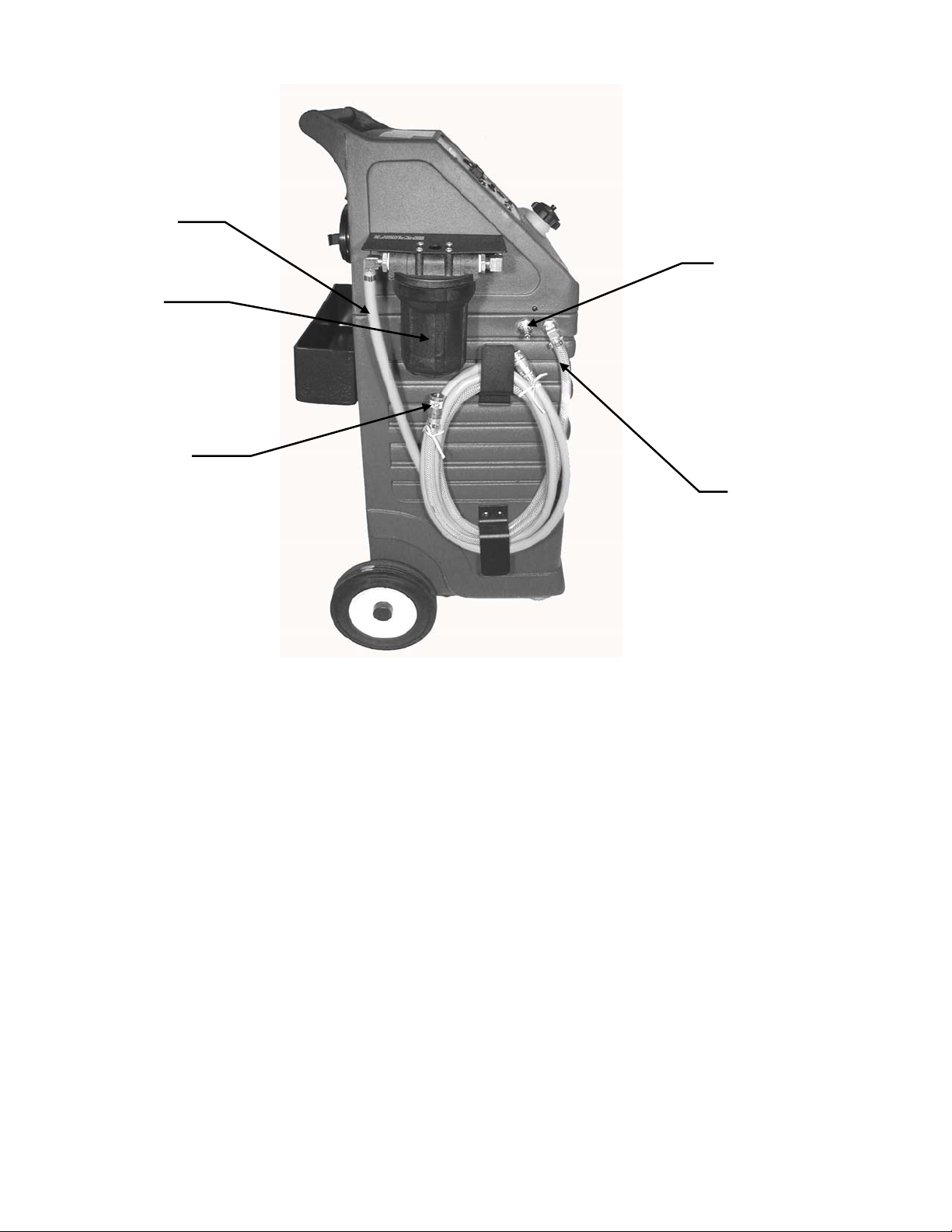
Left View
A
C
B
F.
D
A. RED / Used Coolant
Service Hose
♦ Receives used coolant from the vehicle when
connected
♦ Used to evacuate the vehicle’s coolant in the
vacuum mode
B. Quick Coupler
C. Filter Assembly
D. Clear Braided Disposal
Hose
E. Waste Tank Access
nipple.
Secures the needed adaptor to the unit’s service
hose.
Stainless Steel 50 Mesh Screen for used coolant
filtration.
Inserts into the shop’s coolant recycling system or
collection tank for proper disposal of used coolant.
Used for capturing waste fluid during services.
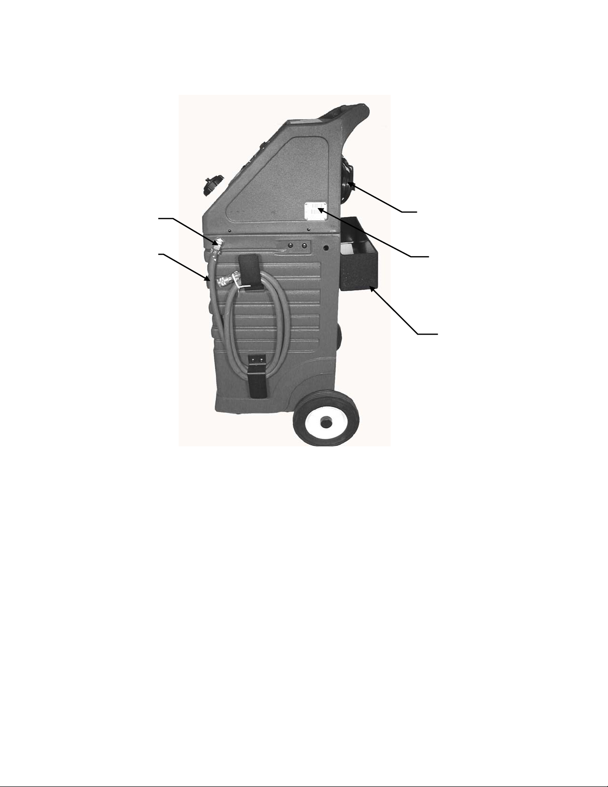
Right View
C
A
B
A. Quick Coupler
B. GREEN / New Coolant
Service Hose
C. Battery Cables
D. Serial Number Tag
E. Adapter Tray
Secures the needed adaptor to the unit’s service hose.
Provides NEW coolant to the vehicle during services.
Positive (Red) & Negative (Black) battery
Model & Serial number label.
Storage tray for adapters.
D
E
Adds coolant to the vehicle in the “top-off” mode.
connections

Theory of Operation
Detailed descriptions of the various operations, switches and indicators that make up
the Coolant Clean-III’s control panel are listed below.
3- Position Power Switch:
♦ When the main power switch is in the OFF position (CENTER):
(And unit connected to an operating vehicle) The unit will be in a flow through or “by-pass” mode.
At this time, coolant flow from the vehicle passes through the unit and returns to the vehicle.
The OFF position will also disable the unit’s audible, low-level alarm (if activated). At this time the
“Top-off” feature will be operational until the unit has been disconnected from power.
♦ When the main power switch is pressed to the VACUUM position (LEFT):
The Coolant Clean-III’s vacuum pump and 2-way solenoid will activate simultaneously and apply
vacuum to the system being serviced. In VACUUM mode, used coolant will be pulled from the
vehicle through the unit’s RED / vacuum hose, passing through the unit’s filter screen assembly
then exhausted from the unit through the CLEAR BRAIDED disposal hose (which should be
inserted into the shop’s coolant recovery system or connected to the waste tank ‘nipple of the
Coolant Clean-III’s waste capture tank.).
♦ When the main power switch is pressed to the SERVICE position (RIGHT):
The CoolantClean-III’s Green “service in progress” indicator will illuminate, the pressure pump
and the vacuum pump will activate simultaneously supplying new coolant from the reservoir tank,
through the pressure pump and to the vehicle being serviced through the unit’s GREEN / new
coolant hose. At this time, the vehicle’s used coolant flow will be routed to the unit through the
unit’s RED / used coolant hose & exhausted from the unit through the CLEAR BRAIDED disposal
hose (which should be inserted into the shop’s coolant recovery system or connected to the units
waste capture tank ‘nipple’.)
2-Position On-Off Switch: (Top-Off function)
♦ When activated, this feature will:
Disable the unit’s Amber “Low Fluid Level “ indicator (If illuminated).
Override low-level “by-pass” mode to provide additional coolant from the unit’s reservoir to top-off
the vehicle’s cooling system anytime the unit is connected to power. Coolant will be provided
through an open-ended adaptor connected the unit’s GREEN / new coolant hose.
Empty waste switch: Used to drain- (empty) the waste fluid capture tank. Note:
Hoses must be switched before “draining”. The clear-braided waste hose must be
disconnected from the waste tank nipple and an adapter inserted into it’s coupler.
Direct the clear hose into the shops waste tank. Hook up the RED hose coupler to
the waste tank “nipple”. Then activate the empty waste switch. Pump should stop
automatically when waste tank is empty.
 Loading...