

MotorVac COOLANTCLEAN-1000 User Manual
MOTORVAC TECHNOLOGIES INC.
COOLANTCLEAN-1000
MODEL#MCF-5150
Engine Cooling System Service
MANUAL #100-5150
Operator’s Manual

Table of Contents
Introduction…………………………………………………………………………………………….………iii
Overview………………………………………………………………………………………………………...4
System Features and Functions……………………………………………………………………...…..1-1
Control Panel Features and Functions………………………………………………………………...1-1
Left View…………………………………………………………………………………………………..1-2
Right View…………………………………………………………………………………………………1-3
Theory of Operation……………………………………………………………………………………...1-4
Safety Information…………………………………………………………………………………………...2-1
Before You Begin…………………………………………………………………………………………….3-1
First Time Operation..................................................................................................................... 3-1
Cooling System Service Procedure ................................................................................................4-1
Troubleshooting and Additional Help.............................................................................................5-1
Appendix A - Maintenance ...............................................................................................................A-1
Maintenance Procedures.............................................................................................................. A-1
Replacing the Unit’s Filter. …………………………………………………………………. ............. . A-1
Maintenance Record ....................................................................................................................A-2
Appendix B - System Accessories..................................................................................................B-1
Included Adaptors………………………………………………………………………………..………B-1
Optional Adaptors………………………………………………………………………………..………B-2
Appendix C - Parts ............................................................................................................................C-1
Service Parts. C-1
Ordering Parts……………………………………………………………………………………………C-1
Introduction
Congratulations on your selection of the COOLANTCLEAN 1000 Cooling System Service Unit.
By choosing this product, you are acquiring the most technologically advanced method
available for performing cooling system services and coolant exchanges.
The COOLANTCLEAN 1000 System is designed to service most automotive applications by
exchanging most of the coolant in the vehicle’s cooling system. Connections to the vehicle are
achieved with the supplied adaptors. Partial service can be completed by using the cone
adapter in the radiator fill neck. Complete service can be completed by using the adapters that
install in-line between the vehicle’s radiator & upper radiator hose.
Once connected, the unit can be safely used to:
Relieve system pressure to provide safe, worry-free access to the vehicle’s system.
Pull down or evacuate the coolant levels in the radiator and overflow tanks,
providing a safe connection of the unit without hot coolant worries.
Service the cooling systems by exchanging the coolant in the vehicle’s system.
Completely or partially empty a vehicles coolant system for repair procedures.
Evacuate air from empty coolant system in order to eliminate air pockets.
Refill coolant system with clean or used fluid saved from prior evacuation.
With the vehicle’s engine off, the COOLANTCLEAN 1000 unit can be used to vacuum off the
pressure from a hot system prior to removal of the radiator cap. Partial evacuation of the coolant
can be accomplished using the cone adapter in the radiator neck. Complete evacuation of the
coolant can be accomplished by loosening the upper radiator hose connection to allow air into
engine.
It is recommended that vehicles (with conventional type coolant) have their cooling systems
serviced every 15,000 to 30,000 miles, or according to the manufacturer’s recommendations.
Periodic service intervals are recommended to provide proper protection against overheating
and breakdown of the coolant’s protective properties. Old coolant can no longer protect against
rust or acids that can break down metal & aluminum parts in the system.
Have all associated personnel study this Operators Manual completely to become thoroughly
familiar with
the COOLANTCLEAN 1000 Cooling System Service Unit & it’s proper operation.
IMPORTANT
The COOLANTCLEAN 1000 Cooling System Service is designed to work
EXCLUSIVELY
With standard automotive coolant formulations.
Use of additives or chemicals during services may cause operational failure of
the COOLANTCLEAN 1000 Service System and will void the manufacturer’s
warranty.
See the warranty card for specific details.

Overview
This manual contains all the information you need to use the COOLANTCLEAN 1000 Service Equipment.
Please make sure all technicians using the unit & performing services read this manual and have it within
easy reach whenever the unit is being used.
The following is a quick reference to the information in this manual.
System Features and Functions
This chapter describes the COOLANTCLEAN 1000 Service System’s Controls, Connections and
their proper usage.
Safety Information
Read & adhere to the safety guidelines in this chapter at all times!
Before You Begin
Follow the instructions in this chapter to prime the unit & check operation before using
the COOLANTCLEAN 1000 unit for the first time.
Service Procedure
This chapter contains a step-by-step setup and service procedures for:
Relieving system pressure
Evacuating coolant in the radiator or overflow tank
Performing a cooling system service.
Troubleshooting and Additional Help
Turn to this chapter in the unlikely event you have problems with your COOLANTCLEAN 1000
service equipment or need additional help.
Appendices - Maintenance, Accessories, and Parts
The appendices contain routine maintenance procedures for the COOLANTCLEAN 1000 such as
cleaning the filter, lists of any available accessories & replacement parts.
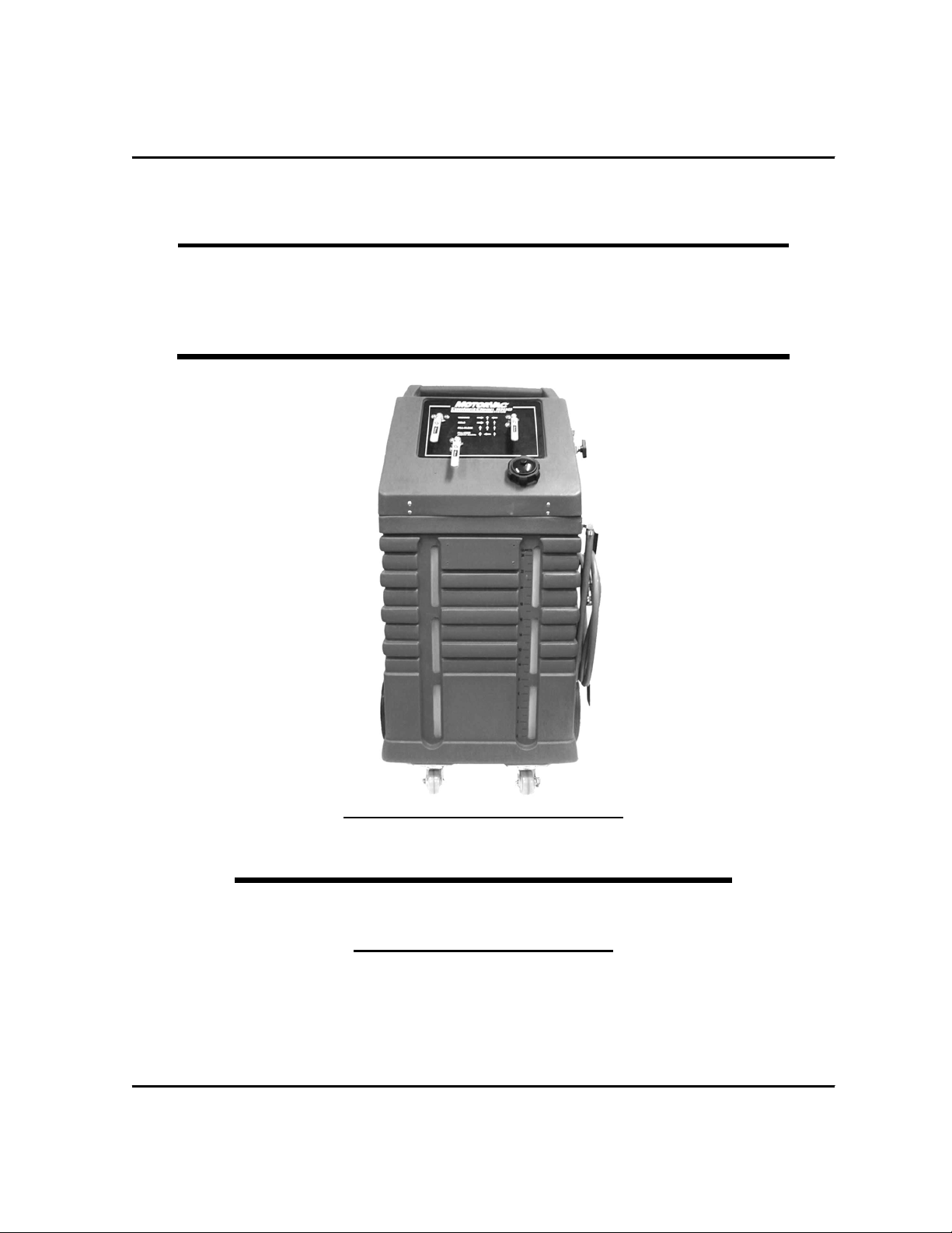
System Features and Functions
The front of the COOLANTCLEAN 1000 Cooling System Service unit contains the Control Panel,
Fluid Filler Neck for adding coolant to the unit’s Reservoir Tank & Tank Level Indicator.
System overview and descriptions follow.
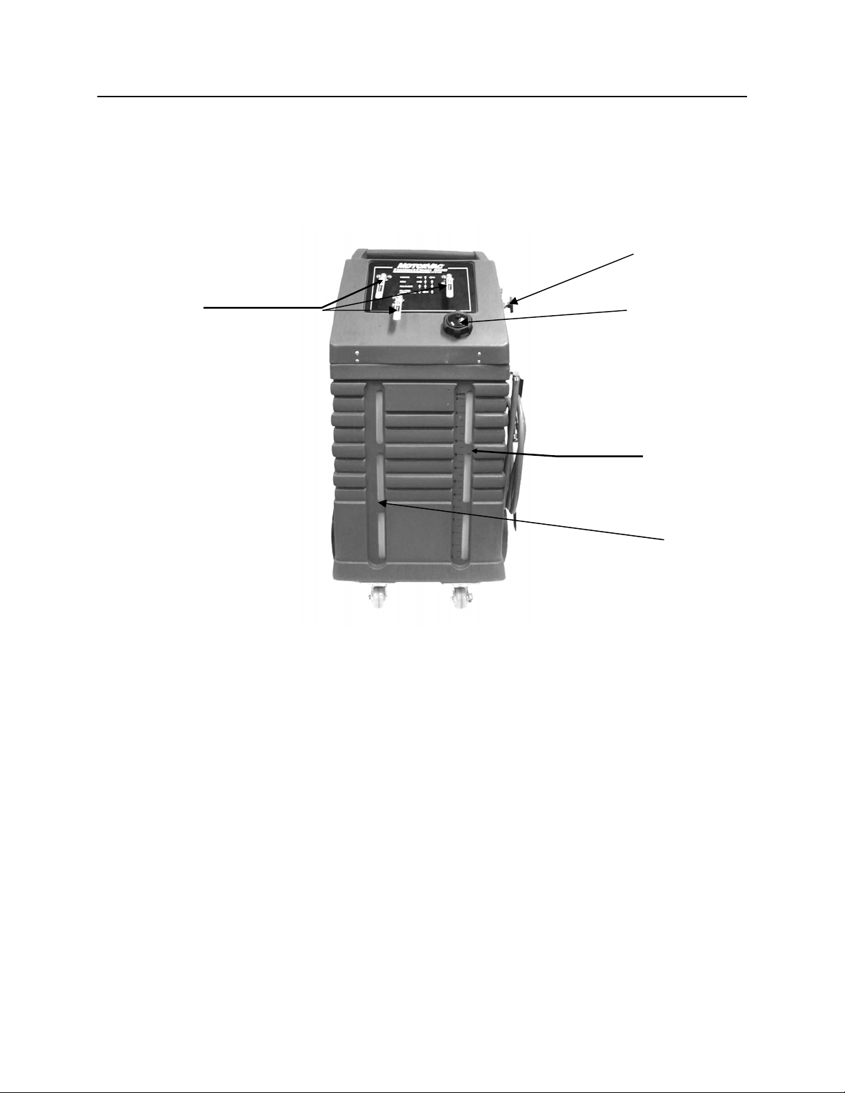
Front View - Control Panel Features and Functions
B.
A.
A. Flow Control Valves
B. Air input control valve. Turns on and off the ‘shop’ air flow to the pump.
Controls flow directions for vacuum, hold vacuum, and fill
functions
C.
D.
E.
C. Clean fluid tank fill neck Access to clean fluid tank. (26 quarts maximum capacity)
D. Clean fluid tank level
window
E. Used/waste fluid tank level
window
Visual access to monitor fluid level in clean fluid tank.
Visual access to monitor fluid level in used fluid tank.
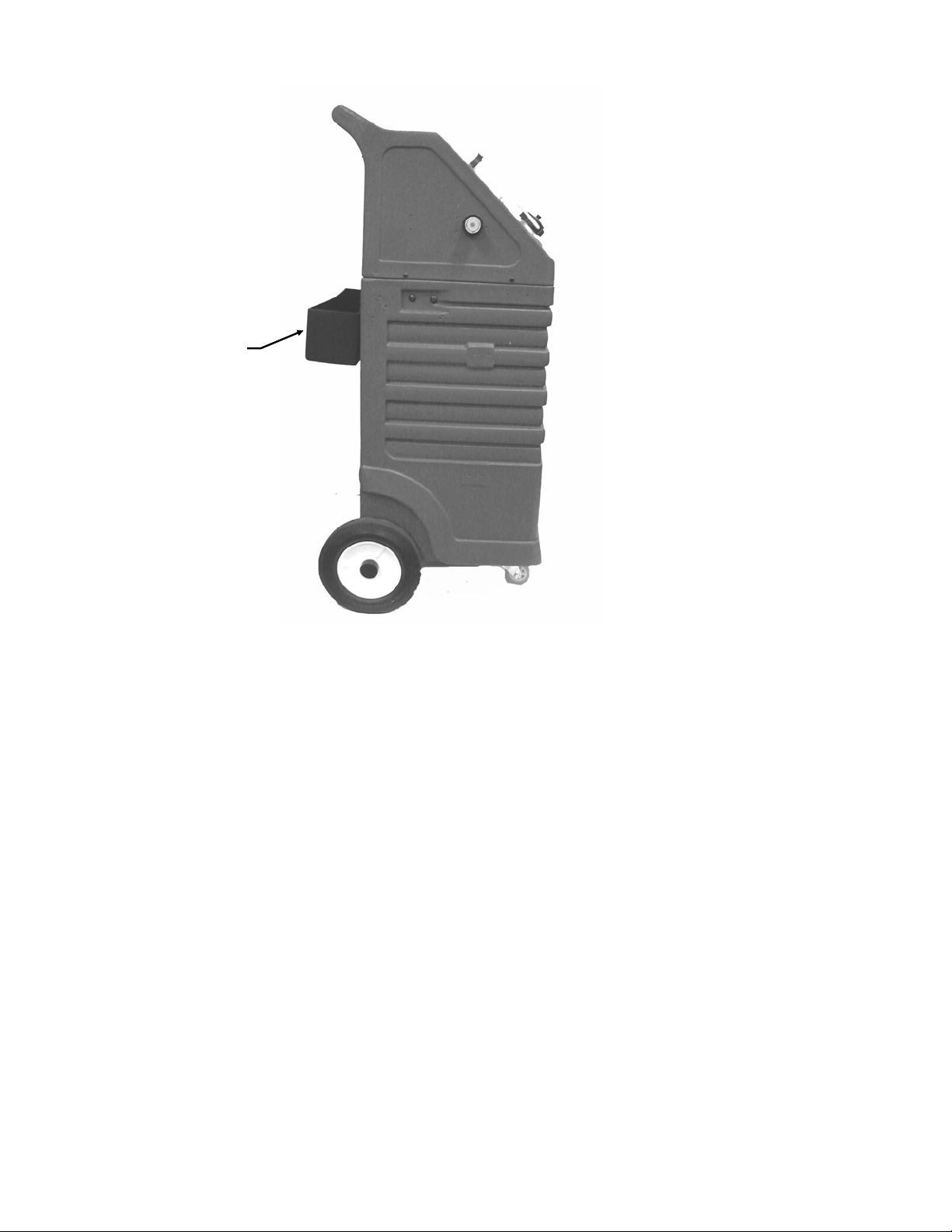
Left View
A.
A. Adapter Tray
Used to store adapters used in vehicle hookups.
 Loading...