

Page 1

XLS Series Solid State Soft Starter 39 - 1250A
XLS SERIES
Solid State Soft Starter
39 - 1250 A
INSTALLATION & OPERATION
MANUAL
Motortronics
- 23 -
REV 2
08110601MN
Page 2

XLS Series Solid State Soft Starter 39 - 1250A
Motortronics
- 24 -
Page 3

XLS Series Solid State Soft Starter 39 - 1250A
Table of Contents
XLS Series
Solid State Soft Starter
39 - 1250A
Chapter 1: Introduction.....................................................1
1.1 General
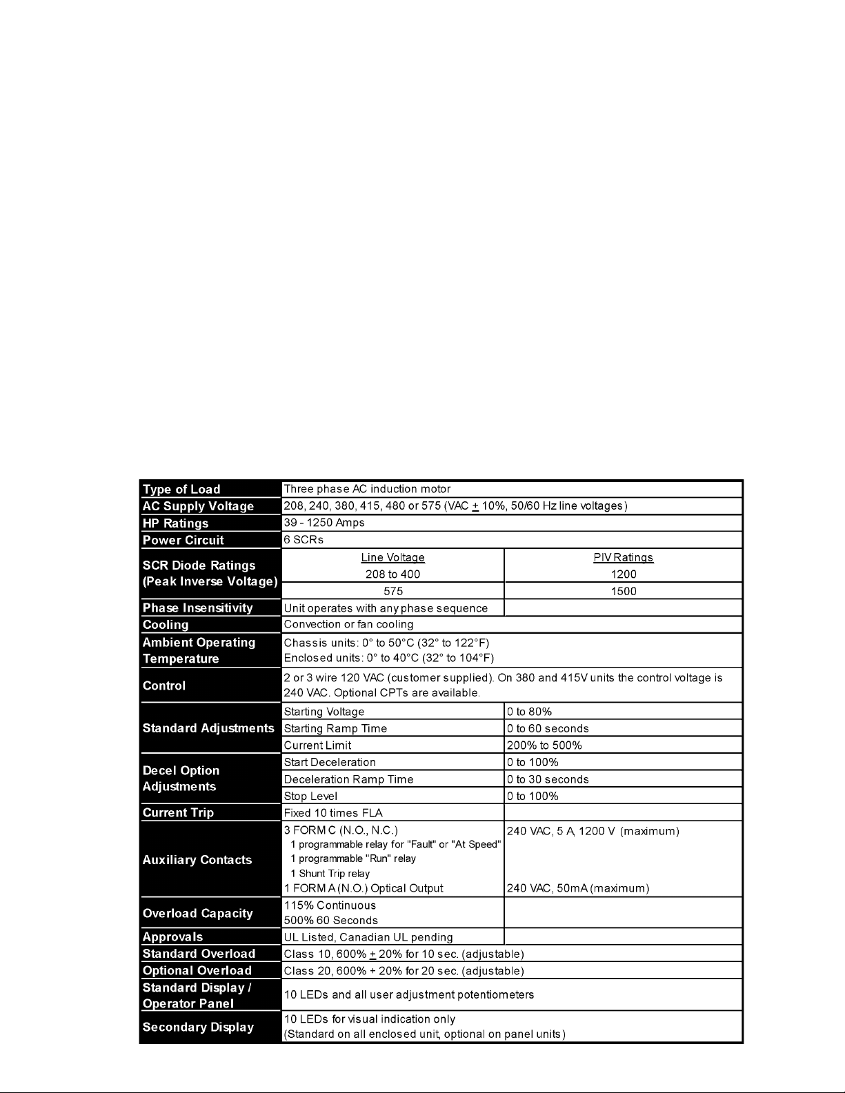
1.2 Specifications and Performance Features
Chapter 2: Installation.......................................................2
2.1 Receiving and Unpacking
2.2 Location
2.3 Initial Unit Inspection
2.4 Warning
2.5 Mounting and Cleaning
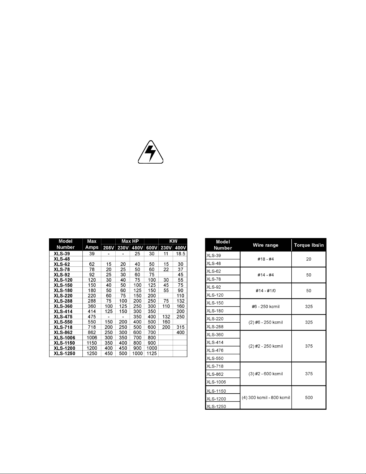
2.6 Power Terminal Wire Range and Tightening Torque
2.7 Dimensions
Chapter 3: Motor Overload Protection............................5
3.1 Thermal Overload Relay
3.2 Overload Relay
3.3 FLA Dial Adjustment
3.4 Manual/Automatic Reset
3.5 Test for Trip Indication
Chapter 4: Connections ................................................... 6
4.1 Power Connections
4.2 Control Connections
Chapter 5: Adjustments ....................................................9
5.1 Introduction
5.2 Acceleration Adjustments
5.3 Deceleration Adjustments
Chapter 6: Start-Up .........................................................1 2
6.1 Start-up Check List
6.2 Sequence of Operation
Chapter 7: Status Indicator LEDs ..................................13
7.1 LED Functions
Chapter 8: Troubleshooting ...........................................14
8.1 Failure Analysis
8.2 SCR Testing Procedure
8.3 Replacing SCR Devices
8.4 Replacing Printed Circuit Boards
Chapter 9: Main Control Board ......................................20
Motortronics
- 25 -
Page 4

XLS Series Solid State Soft Starter 39 - 1250A
Motortronics
- 26 -
Page 5
XLS Series Solid State Soft Starter 39 - 1250A
Chapter 1 - Introduction
1.1 General
The XLS Series solid state reduced voltage soft starter is a six SCR
design which features a voltage/current ramp with an anti-oscillation
circuit for smooth load acceleration. The SCRs are sized to withstand
starting currents of 500% for 60 seconds (compared to 350% for 30
seconds from other manufacturers). The XLS Series features smooth,
stepless ramp control which reduces motor inrush current and excessive
wear on the mechanical drive train components. In addition to having
easy to understand diagnostic lights, the XLS Series can be set up for
the ideal starting cycle. Starting voltage, ramp time, current limit, and
decel control are standard adjustments on the XLS Series. The starting
electrical characteristics of the motor can be matched to the mechanical
characteristics of the drive train for controlled acceleration of the load,
by simply adjusting the unit’s starting torque, ramp time and current
limit potentiometers. The XLS Series includes adjustable overload
protection, shorted SCR detection and phase loss detection. It is factory
wired for 120VAC control voltage (or 240VAC for 415 VAC and 380
VAC units) and three-wire start/stop control. Auxiliary contacts and
provisions for interlocking are also included.
1.2 Specifications and Performance Features
Motortronics
- 1 -
Page 6

XLS Series Solid State Soft Starter 39 - 1250A
Chapter 2 - Installation
2.1 Receiving and Unpacking
Upon receipt of the product you should immediately do the following:
• Carefully unpack the unit from the shipping carton and inspect it for
shipping damage (if damaged, notify the freight carrier and file a
claim within 15 days of receipt).
• Verify that the model number on the unit matches your purchase
order.
• Confirm that the ratings sticker on the unit matches or is greater
than the motor’s HP and current rating.
2.2 Location
Proper location of the XLS Series is necessary to achieve specified
performance and normal operation lifetime. The XLS Series should
always be installed in an area where the following conditions exist:
• Ambient operating temperature:
Chassis unit: 0 to 50°C (32 to 122°F)
Enclosed unit: 0 to 40°C (32 to 104°F)
• Protected from rain and moisture
• Humidity: 5 to 95% non-condensing
• Free from metallic particles, conductive dust and corrosive gas
• Free from excessive vibration (below 0.5G)
• Open panel units must be mounted in the appropriate type of
enclosure. Enclosure size and type must be suitable to dissipate
heat generated by the soft starter. Contact factory for assistance in
sizing enclosures.
2.3 Initial Unit Inspection
• Make a complete visual check of the unit for damage which may
have occurred during shipping and handling. Do not attempt to continue
installation or start up the unit if it is damaged.
• Check for loose mechanical assemblies or broken wires which may
have occurred during transportation or handling. Loose electrical
connections will increase resistance and cause the unit to function
improperly.
• Prior to beginning the installation, verify that the motor and XLS unit
are rated for the proper amperage and voltage.
2.4 Warning!
Do not service equipment with voltage applied! The unit can be
the source of fatal electrical shocks! To avoid shock hazard,
disconnect main power and control power before working on the
unit. Warning labels must be attached to terminals, enclosure
and control panel to meet local codes.
Motortronics
- 2 -
Page 7
XLS Series Solid State Soft Starter 39 - 1250A
2.5 Mounting and Cleaning
When drilling or punching holes in the enclosure, cover the electrical
assembly to prevent metal filings from becoming lodged in areas which
can cause clearance reduction or actually short out electronics. After
work is complete, thoroughly clean the area and reinspect the unit for
foreign material. Make sure there is sufficient clearance (six inches)
all around the unit for cooling, wiring and maintenance purposes. To
maximize effective air flow and cooling, the unit must be installed with
its heat sink ribs oriented vertically and running parallel to the mounting
surface.
Warning!
Remove all sources of power before cleaning the unit.
In dirty or contaminated atmospheres the unit should be cleaned on a
regular basis to ensure proper cooling. Do not use any chemicals to
clean the unit. To remove surface dust use 80 to 100 psi, clean, dry
compressed air only. A three inch, high quality, dry paint brush is
helpful to loosen up the dust prior to using compressed air on the unit.
2.6 Power Terminal Wire Range and Tightening Torque
Note: All wiring must be sized according to NEC standards.
Motortronics
- 3 -
Page 8
XLS Series Solid State Soft Starter 39 - 1250A
y
y
y
y
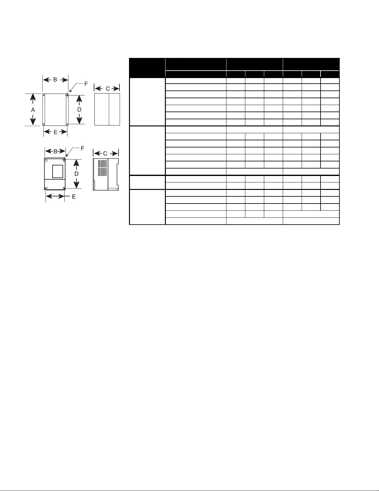
2.7 Dimensions
Enclosure
XLS-6 to XLS-32 12.8 10.9 5.5 12.3 10.3 0.28
XLS-39 to XLS-120 16.5 10 10 15.9 9 0.28
XLS-150 to XLS-180 20 20.1 12 18.5 17.5 0.44
PANEL
NEMA1
NEMA 4/4X
NEMA12
XLS-220 to XLS-288 27 20.1 11.2 25.5 17.5 0.44
XLS-360 to XLS-550 29.5 20.1 11.5 25.5 17.5 0.44
XLS-718 to XLS-1006 45 33 12.8 43.3 31.3 0.44
XLS-1150 to XLS-1250 33 33 15.2 31.2 31.2 0.44
XLS-6 to XLS-32
XLS-39 to XLS-120 16.5 10 10 15.9 9 0.28
XLS-150 to XLS-180 32.3 24.3 13.3 31.3 18 0.44
XLS-220 to XLS-288 38.3 24.3 13.3 37.3 18 0.44
XLS-360 to XLS-550 44.3 30.3 13.3 43.3 24 0.44
XLS-718 to XLS-1006 50.2 36.3 15.5 49.3 30 0.4
XLS-1150 to XLS-1250
XLS-6 to XLS-11 11.7 8.9 9 9 8.4 0.28
XLS-18 to XLS-78 15.7 12.2 10 12 11 0.28
XLS-92 to XLS-120 24 24 12.9 22.5 22.5 0.5
XLS-150 to XLS-288 36 30 16.9 34.5 28.5 0.5
XLS-360 to XLS-550 48 36 16.9 46.5 34.5 0.5
XLS-718 to XLS-1006 72.1 48.1 20
XLS-1150 to XLS-1250
Model
Number
Overall
Dimensions
Mounting
Dimensions
ABCDEF
Not Available Not Available
Contact Factor
Contact Factor
Contact Factor
Floor Mounted
Contact Factor
Motortronics
- 4 -
Page 9

XLS Series Solid State Soft Starter 39 - 1250A
Chapter 3 - Motor Overload Protection
3.1 Thermal Overload Relay
The XLS Series provides motor overload protection using an adjustable
solid state overload relay. The standard XLS Series is furnished with a
Class 10 overload, providing an overload rated at 600% current for 10
seconds. Class 20 overload relays, providing an overload rated at 600%
current for 20 seconds, are also available.
3.2 Overload Relay
The solid state overload relay has an adjustable FLA range set by a
dial. The tripping current corresponds to 110% of the set current.
FLA Adjustable Dial
3.3 FLA Dial Adjustment
The overload relay dial must be set to the number from the overload
settings label that corresponds to the set surrent.
OVERLOAD RELAY DIAL SETTING =
WARNING!
To provide continued protection against fire or shock hazard,
the complete overload relay must be replaced if burnout of the
heater element occurs.
FLA
CT RATIO
3.4 Manual/Automatic Reset
Manual or automatic reset can be selected with the blue button. The
appropriate setting is selected by pressing and turning the button.
Note:
When the automatic restart operation is selected the start
warning portion of this label must be placed as to be visible
after installation. Label states as follows:
WARNING: MOTOR CONNECTED TO THIS EQUIPMENT
MA Y START AUT OMA TICALLY WITHOUT W ARNING.
Example of Warning Label
3.5 T est for T rip Indication
The switch position indicator also incorporates a test function which,
when activated, simulates a tripped overload relay. Both auxiliary
contacts are actuated and the switch position is indicated. This test
is recommended to ensure that the motor protection is active. Checking,
or changing the overload is recommended on major faults.
Motortronics
- 5 -
Page 10

XLS Series Solid State Soft Starter 39 - 1250A
Chapter 4 - Connections
4.1 Power Connections
Connect appropriate power lines to the unit input terminals marked L1, L2,
L3. Avoid routing power wires near the control board. Connect the motor
leads to the unit terminals marked T1, T2, T3. Refer to NEC standards for wire
length and sizing. Never interchange input and output connections to the unit.
This could cause excessive voltage in the control logic circuit and may damage
the unit.
the load side of the unit. The SCRs will be seriously damaged if
capacitors are located on the load side. The unit cannot be tested without
a motor or other test load connected to the load side of the unit. It may be
necessary to use a load bank to test the unit without a motor. Note that line
voltage will appear across the output terminals if there is no motor or load
connected to the unit. In areas where lightning is a significant problem, stationtype air gap lightning arrestors should be considered and utilized on the input
power source.
Note:
Note:
Never connect power factor correction capacitors on
Some units may have the overload on the load side of the starter.
XLS Series Unit
TB1
Note: If power is used for
additional accessory items
(Lights, fans, etc.) contact factory
for sizing.
Power Connections
4.1.1 Grounding
Connect the ground cable to the ground terminal as labeled on the unit. Refer
to the National Electrical Code for the proper ground wire sizing and be sure
that the ground connector is connected to earth ground.
4.2 Control Connections
4.2.1 Control Power Connections
Separate 120VAC supply is required (240VAC for 380V and 415V applications).
The control voltage should be connected to pins 1 and 6 of TB1. This control
voltage must be customer supplied, unless an optional control power
transformer (See chart) has been supplied with the unit. On units rated below
100 HP, the TB1 terminal block is located on the main control board.
Recommended Transformer Sizes for Control Power
Motortronics
- 6 -
Page 11

XLS Series Solid State Soft Starter 39 - 1250A
4.2.2 Two-Wire Connection
An alternate connection for unattended operation replaces start/stop
push buttons by connecting a maintained contact closure between
TB1
Two-Wire Connection
TB1
Three-Wire Connection
pins 3 and 5 on TB1. When the maintained contact is used for start/
stop it is necessary to set the overload relay to the manual reset
position. This will prevent the motor from restarting if the thermal
overload trips and then cools off (refer to Chapter 9 for 120 VAC
connections and interlocks). Note: When two-wire connection
method is used, the start circuit must be interlocked to prevent
automatic restart when either of the two protective devices
(overload or thermostat) reset. Thermostats always automatically
reset on cool down.
4.2.3 Three-Wire Connection
For standard 3-wire control connect 120VAC (or 240VAC for 415V and
380V applications) to pins 1 and 6 of TB1. Connect N.C. (normally
closed) stop button between pins 3 and 4 of TB1. Connect N.O.
(normally open) start button between pins 4 and 5 of terminal block
TB1.
4.2.4 Resetting Faults
To reset faults, remove the control power for two seconds to clear the
fault condition. The unit will also accept a remote reset command via
a N.O. dry contact at TB5 located on the main control board, or press
the reset button SW2 located near TB5. See Chapter 9 for the main
control board layout. Check the unit to ensure that the fault has been
corrected before reenergizing unit.
Factory Settings
4.2.5 Relay Contacts
All the relay contacts are FORM C common (N.O., N.C.), except the
optical triac output. Motortronics recommends fusing all contacts with
external fuses. TB2 is the terminal block for all external contacts.
Each contact is explained in the following sections. See Chapter 9 for
main control board layout.
TB2
240 VAC
5 A
1200 VA
240 VAC
5 A
1200 VA
WARNING!
To make changes in the dip switch settings, the front cover of the
unit may need to be removed. Do not make adjustments with
power applied to the unit, serious injury may result. Do not use a
screwdriver or other tool to make adjustments, damage to the
unit may result.
240 VAC
5 A
1200 VA
Optical Triac
Driver
240 VAC
50 mA
Motortronics
- 7 -
Page 12

XLS Series Solid State Soft Starter 39 - 1250A
4.2.6 Programmable Relay
The XLS includes a programmable relay on TB2 which is located on
the main control board. The relay is rated for 240 VAC, 5 A and 1200
VA. The relay responds to either a fault condition or an up-to-speed
condition. For the relay to act as a fault relay, turn dip switch 1(SW1),
located on the main control board, “ON” and dip switch 2 “OFF” (Factory
Setting). For an up-to-speed contact turn dip switch 1 “OFF” and dip
switch 2 “ON”. Refer to Chapter 9 for dip switch location. In the up-tospeed mode, the programmable relay can be used to control a bypass
contactor, or signal other systems that need to be brought online after
the motor has reached full speed.
4.2.7 Run Contacts
Auxiliary contacts are available on TB2. These contacts are rated 240
VAC, 5 A, 1200 VA and are for external use. Auxiliary contacts energize
(change state) when the start command is given and de-energize
(change back) when stop, or fault, condition occurs. In the decel mode,
the run contact can be modified to drop out at the stop command, or
to stay latched until the end of the decel command. Dip switch 5 is
“ON” and dip switch 6 is “OFF” for normal start/stop mode. To keep
the run contact latched until the end of decel, turn dip switch 6 “ON”
and dip switch 5 “OFF”. The decel mode must be enabled by turning
dip switch 4 “OFF”. Refer to Chapter 9 for the main control board
layout.
4.2.8 Emergency Shunt Trip Relay
The shunt trip relay at TB2 on the main control board will activate
when a shunt trip signal is received from the motor’s monitoring logic.
This relay is rated for 240 VAC, 5 A, 1200 V. This relay can be used in
an external shunt trip circuit. Check inrush rating on shunt trip breaker.
This relay is not programmable and only operates if current is flowing
when the XLS is in the off mode. Refer to Chapter 9 for the main
control board layout.
4.2.9 Fault Signal
An optical AC switch triac driver is used for fault indication. This signal
energizes with the fault LED. The optical output is rated for 240 VAC,
50 mA (maximum).
Motortronics
- 8 -
Page 13

XLS Series Solid State Soft Starter 39 - 1250A
Chapter 5 - Adjustments
5.1 Introduction
It is best to operate the motor at its full load starting condition to
achieve the proper time, torque and ramp settings. Note that the
potentiometers have a turning range of 3/4 revolution. Forcing the
potentiometer beyond this range will damage the unit. Initial settings
are set to accommodate most motor conditions. TRY INITIAL
SETTINGS FIRST .
5.2 Acceleration Adjustments
The unit is set at the factory with typical starting characteristics that
perform well in most applications. When the system is ready to start,
try the initial unit settings. If the motor does not come up to speed,
increase the current limit setting. If the motor does not start to turn as
soon as desired, raise the starting voltage adjustment. The unit has
three accel adjustments. Adjustment description and procedures are
described as follows:
5.2.1 Starting Voltage Adjustment/Rotation Check
Factory Setting = 60% of line voltage
Detail of Operator Interface Module
Range = 0% - 100% of line voltage
Starting voltage adjustment changes the initial starting voltage level to
the motor. Start voltage is increased by rotating the starting voltage
potentiometer clockwise. Turn dip switch 3 to the “OFF” position,
disabling the ramp function and allowing starting voltage adjustment.
This will permit adjustment of the starting voltage without activating
the ramp. Turn the starting voltage potentiometer FCCW (fully counterclockwise). Apply power to the XLS and give the start command.
Observe that the motor does not rotate. Slowly increase the start
voltage by turning the potentiometer in a clockwise direction until the
motor begins to rotate. When the motor begins to rotate, give a stop
command and remove both line and control voltage. Reset dip switch
3 for the “ON” position to re-enable the ramp function. The minimum
effective starting voltage is now set. Do not leave dip switch 3 in
the off position!
Note:
Use this time to check the direction of rotation without full
speed operation.
5.2.2 Ramp Time Adjustment
Factory Setting = 10 sec.
Range = 0 - 60 sec.
Ramp time adjustment changes the amount of time it takes to reach
the current limit point or full voltage if the current limit point was not
reached. Acceleration time (ramp) can be increased by rotating the
ramp time potentiometer in a clockwise direction. The ramp time
adjustment is made after the starting torque has been set. Set the
ramp time potentiometer by slowly rotating it until the desired ramp
time is reached. The unit should be stopped and restarted to see if the
desired acceleration time has been achieved
Note:
Refer to your motor manual for the maximum number of starts
allowed by the manufacturer and do not exceed the recommended
number.
Motortronics
- 9 -
Page 14

XLS Series Solid State Soft Starter 39 - 1250A
5.2.3 Current Limit Adjustment
Factory Setting = 350% of unit FLA
Range = 200% - 500% of unit FLA
The current limit adjustment is factory set for 350% of the unit’s rating.
The range of adjustment is 200% to 500%. The main function of current
limit is to cap the peak current. It may also be used to extend the
ramping time if desired. The interaction between the voltage ramp and
the current limit will allow the soft start to ramp the motor until the
maximum current is reached and the current limit will hold the current
at that level. The current limit must be set high enough to allow the
motor to reach full speed. The factory setting of 350% is a good starting
point. Do not set the current limit too low on variable starting
loads, this will cause the motor to stall and eventually cause
the system overloads to trip.
Note:
If the motor does stall, refer to the motor manufacturer for the
proper cooling time.
5.3 Deceleration Adjustments
Decel extends the stopping time on loads that stop too quickly, and
will provide smooth deceleration until the load stops. Three adjustments
optimize the deceleration curve to meet the most demanding
requirements. T ry factory settings before adjusting.
The unit is shipped from the factory with the decel feature
disabled. T urn off dip switch 4 to enable the decel control feature
before making any adjustments. Apply power and adjust the soft
start before enabling or modifying the deceleration adjustments. Both
acceleration and deceleration adjustments should be made under
normal load conditions. The deceleration adjustments are made in
the same manner as the starting adjustments; turning the potentiometer
clockwise increases the setting, turning the potentiometer counterclockwise decreases the setting.
5.3.1 Step Down Voltage Adjustment
Factory Setting = 60% of line voltage
Range = 0% - 100% of line voltage
The step down voltage adjustment eliminates the dead band in the
deceleration mode that is experienced while the voltage drops to a
level where the motor deceleration is responsive to decreased voltage.
This feature allows for an instantaneous drop in voltage when
deceleration is initiated.
Motortronics
- 10 -
Page 15

XLS Series Solid State Soft Starter 39 - 1250A
5.3.2 Stop Voltage Level
Factory Setting = 20% of line voltage
Range = 0% - 100% of line voltage
The stop voltage level set point is where the deceleration voltage drops
to zero.
Detail of Operator Interface Module
5.3.3 Deceleration Ramp Time
Factory Setting = 5 sec.
Range = 0 - 30 sec.
The deceleration ramp time adjusts the time it takes to reach the stop
voltage level set point. The unit should be restarted and stopped to
verify that the desired acceleration time has been achieved.
Note: Do not exceed the motor manufacturer’s recommended
number of starts per hour. When calculating the number of starts
per hour, a decel curve should be counted as a start curve. For
example: recommended number of starts per hour = 6, allowable
starts with decel cycle per hour = 3.
Motortronics
- 11 -
Page 16

XLS Series Solid State Soft Starter 39 - 1250A
Chapter 6 - Start-up
6.1 Start-up Check List
• Supply voltage matches the rated supply voltage of the unit.
• Horsepower and current ratings of the motor and unit match or the
unit is higher rating.
• Initial ramp time and torque adjustments have been checked.
• Power lines are attached to the unit input terminals marked L1, L2
and L3.
• Motor leads are connected to the lower terminals marked T1, T2,
and T3.
• Appropriate control power is applied and/or control connections
have been made.
• “Power on” light located on the front of the unit turns on when
control power is applied.
• The motor area and equipment are clear of people and parts
before start-up.
• The thermal overload is set to motor rating.
6.2 Sequence of Operation
• Apply control power and check that the “Power On” LED comes
on.
• Apply three phase power to the unit. The motor should run only
when the start command is applied.
• Apply the start command. The “Run” LED should light up and the
motor should begin to accelerate.
• When the motor reaches full speed, the “At Speed” LED comes
on.
Status Indicator LEDs
• If the motor decelerates, or stops, during the acceleration period,
hit the stop button immediately and open the disconnect line.
Sequence of Operation
If the unit does not follow this operational sequence please refer to
Chapter 8 - Troubleshooting.
Motortronics
- 12 -
Page 17

XLS Series Solid State Soft Starter 39 - 1250A
Chapter 7 - Status Indicator LEDs
7.1 LED Functions
The unit has 10 LEDs on the status display.
Status Indicator LEDs and
operator panel
Motortronics
- 13 -
Page 18

XLS Series Solid State Soft Starter 39 - 1250A
Chapter 8 - T roubleshooting
8.1 Failure Analysis
Motortronics
- 14 -
Page 19

XLS Series Solid State Soft Starter 39 - 1250A
Motortronics
- 15 -
Page 20

XLS Series Solid State Soft Starter 39 - 1250A
8.2 SCR Testing Procedure
Remove both line power and control power from the unit and lock
out. Disconnect any two motor load leads and any two line leads.
Disconnect the SCR connections to main control board J5, J6 and
J7. Refer the Chapter 9 for the main control board layout. Note the
type of color coding of the wires connected to J5, J6 and J7.
Motortronics uses two possible configurations. Both configurations
have 4 wires going to each plug. The first configuration consists of 4
wires color coded black, yellow, grey and white. The second
configuration consists of 4 wires color coded red, white, red, white.
The testing procedure for SCRs is comprised of two separate tests.
The first one tests the anode to cathode integrity of the SCR by
performing the following ohm checks:
The second tests the gate to cathode integrity of the SCR. Place
the leads of an ohm meter into the receptacle that was unplugged
from the main circuit board. Ohm the pair of wires on one end of the
plug. Then ohm the pair of wires on the other end of the plug. The
chart below indicates good versus bad readings.
Note: If any of the above readings are out of specifications,
replace the faulty SCR.
Note: The best way to test an SCR is with an SCR Tester and
look for leakage current less than the manufacturer specified
values.
Motortronics
- 16 -
Page 21

XLS Series Solid State Soft Starter 39 - 1250A
8.3 Replacing SCR Devices
Two types of SCRs are used in the XLS Series depending on the
horsepower/amperage rating of the unit. Isolated SCRs are used in
smaller units and “hockey puck” type SCRs are used in larger units.
(Refer to Chapter 9 for the main control board layout.)
8.3.1 Changing an Isolated SCR
• Remove both line and control power from unit, tag and lock out.
WARNING!
Failure to remove both line and control power before starting
this procedure may cause personal injury or death.
• Label the location of wires connected to the SCR.
• Remove the mounting screws, lugs and associated wiring from the
existing SCR.
• Make sure the surface to which the power module mounts is clean
and free from dirt, nicks and scratches.
• Apply thermal grease uniformly along the grooved area. Spread the
grease thinly (3 mil thick) to completely cover the base of the
power module and minimize air pockets. The grease must be free
of contamination.
• Replace the screws and tighten down firmly. All mounting screws
should be 44lb/in. Units with a maximum amperage rating of up to
48A, should use 26 lbs/in busbar and power lugs. Units with a
maximum amperage of 60A - 120A should use 44 lbs/in busbar
and power lugs.
• Reconnect all busbars, lugs and wires. Check to make sure the
gate and cathode are wired correctly. Use the following chart to
verify the wiring of J5, J6 and J7:
• After verifying that all wiring is correctly connected, test the SCR.
Motortronics
- 17 -
Page 22

XLS Series Solid State Soft Starter 39 - 1250A
8.3.2 Changing a Hockey Puck Type SCR
• Remove both line and control power from unit, tag and lock out.
Warning!
Failure to remove both line and control power before starting
this procedure may cause personal injury or death.
• Motortronics uses two types of clamps with gauges for reading the
amount of force on the device. The first type of force gauge uses a
spin washer. When the proper force is applied, the washer will be
free to spin. The second type of gauge uses a step indicator on the
end of the lever. Before proceeding, note the type of clamp used
and, if the clamp has a step indicator, document the position of the
indicator before removing the clamp to facilitate proper mounting of
the new SCR device.
• Label the location of the wires connected to the SCR.
• Remove any lugs, snubbers, printed circuit boards (refer to section
X) and associated wiring that may get in the way of reaching the
faulty SCR. Document the location and wiring of all parts before
removing them to facilitate the reinstallation of the devices later.
• Document the position of the indicator on the SCR clamp. Then
remove the top clamp holding the SCR stack together. Remove the
top heatsink. Use extreme caution when handling the heat sink so it
does not become dented or damaged.
• Remove the faulty SCR device, noting the direction in which the
SCR is oriented. The new SCR puck must be inserted in the same
direction.
• Make sure the SCR mounting surface, tools, and hands are clean
and free from dirt, nicks, and scratches. Do not sand or scrape SCR
mounting surface. If necessary, super fine Scotch Brite pads can be
used to clean the heatsink before installing the new SCR.
• Apply a thin (3 mil thick) layer of thermal grease uniformly along
both sides of the SCR. Spread the grease to cover the entire surface
of both sides of the SCR in a manner that minimizes air pockets.
The grease must be free of contamination.
• Locate the centering pin in the bottom and top of the heatsink and
center it in the SCR hole (making sure that the SCR is pointed in the
same direction as the SCR that was removed in step 6). Locate the
centering pin in the top heatsink and center it in the SCR hole.
Caution: If center pin is not placed correctly it will damage
the SCR and the heat sink. Hand tighten the clamps evenly so
that the same number of threads appear at both ends of the Uclamp. Tighten the clamp 1/4 turn at a time alternating sides of the
U-clamp until the correct force is reached. Check the gauge or spin
washer every time the clamp nuts are tightened 1/4 turn to ensure
that the SCR is not over torqued. The gauge reading should be similar
to the initial reading taken in step 2. If the clamp uses the spin
Motortronics
- 18 -
Page 23

XLS Series Solid State Soft Starter 39 - 1250A
washer gauge, verify that the washer spins freely after clamping.
Once proper force is reached make sure that the SCR pucks are
securely held between the heatsinks and aligned evenly.
• Replace any lugs, MOVs, snubbers, power straps, printed circuit
boards and associated wiring that was removed in step 4. Use the
following chart to verify wiring of J5, J6 and J7:
• After verifying that all wiring is correctly connected, test the SCR
and then test the unit.
8.4 Replacing the Main Control Board
The printed circuit board is not intended to be field repaired. If the
board is faulty, the entire board should be replaced using the
following procedure:
(See Chapter 9 for the main control board layout.)
• Remove three phase power and control power from the unit and
lock out.
• Remove plugs and tag plugs with connector numbers.
• Remove control wires from terminals and tag wires with terminal
numbers.
• Note the settings of all dip switches.
• Remove the mounting screws.
• Remove the old printed circuit board.
• Mount the new printed circuit board.
• Install the mounting screws.
• Set the dip switches to the same position as on the old board.
• Install the control wires onto correct terminals per tag sequence.
• Install the plugs.
• Apply power to the unit and test.
Motortronics
- 19 -
Page 24

XLS Series Solid State Soft Starter 39 - 1250A
Chapter 9 - Main Control Board
Motortronics
- 20 -
Page 25

XLS Series Solid State Soft Starter 39 - 1250A
Warranty Policy
MOTORTRONICS warrants its products to be free from defects in material
and/or workmanship for a period of one year from the date of installation, to
a maximum of 18 months from the date of shipment as indicated by the
unit’s date code. The Company reserves the right to repair or replace any
malfunctioning units under warranty at their option. All warranty repairs must
be performed by the Company factory, or on site by factory authorized service firms or personnel approved by the Company.
Solid state controls have different operating characteristics from those of
electromechanical equipment. Because of these differences and the wide
variety of applications for solid state controls, each application designer must
verify that the solid state equipment is acceptable for his application. In no
event will MOTORTRONICS be liable or responsible for indirect or consequential damages resulting from the use or application of this equipment.
The diagrams and illustrations in this document are included solely for illustrative purposes. Because of the number of different applications,
MOTORTRONICS can not be responsible or liable for actual use based on
the examples or diagrams.
Motortronics
- 21 -
 Loading...