

Motortech VariStep3 Operating Manual
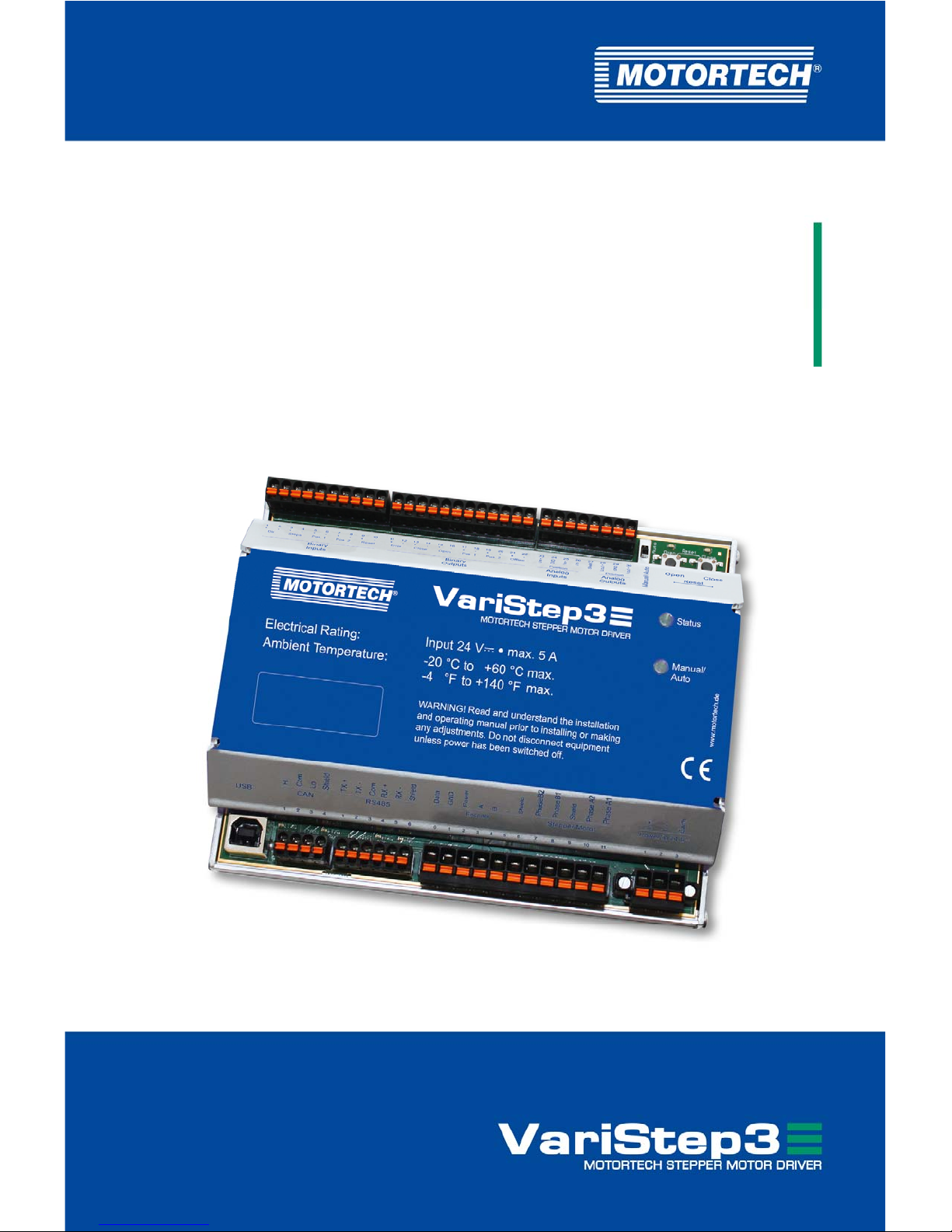
VariStep3 –
Stepper Motor Driver
Operating Manual
P/N 01.50.020 – EN | Rev. 08/2018

Original instructions
Copyright
© Copyright 2018 MOTORTECH GmbH. All rights reserved.
Distribution and reproduction of this publication or parts thereof, regardless of the specific
purpose and form, are not permissible without express written approval by MOTORTECH.
Information contained in this publication may be changed without prior notice.
Trademarks
MOTORTECH products and the MOTORTECH logo are registered and/or common law trademarks
of the MOTORTECH Holding GmbH. All further trademarks and logos displayed or used in this
publication are the property of the respective entitled person.

Rev. 08/2018 3
1 General Information .................................................................................................... 6
1.1 What Is the Purpose of this Operating Manual? ......................................................... 6
1.2 Who Is this Operating Manual Targeted to? ............................................................... 6
1.3 Which Symbols Are Used in the Operating Manual? ................................................... 6
1.4 Which Abbreviations/Acronyms Are Used in the Operating Manual? ........................... 7
2 Safety Instructions ..................................................................................................... 8
2.1 General Safety Instructions ..................................................................................... 8
2.2 Electrostatic Discharge Hazards .............................................................................. 9
2.3 Information on Electric Isolation .............................................................................. 9
2.4 Special Safety Instructions for the Device .............................................................. 10
2.5 Proper Disposal .................................................................................................... 12
3 Intended Use ............................................................................................................. 13
3.1 Functional Description .......................................................................................... 13
3.2 Applications ......................................................................................................... 13
4 Product Description ................................................................................................... 15
4.1 Technical Data ...................................................................................................... 15
4.1.1 Certifications ..................................................................................................... 15
4.1.2 Mechanical Data ................................................................................................ 17
4.1.3 Warning Notices on the Device ............................................................................ 17
4.1.4 Product Identification – Labeling on the Device .................................................... 18
4.1.5 Electrical Data .................................................................................................... 19
4.1.6 Interfaces .......................................................................................................... 20
4.1.7 Overview Drawings ............................................................................................. 21
5 Installation Instructions ............................................................................................. 24
5.1 Installation Instructions ........................................................................................ 24
6 Wiring of the Device ................................................................................................... 25
6.1 Wiring Power Supply ............................................................................................. 27
6.2 Wiring Stepper Motor and Encoder ........................................................................ 28
6.3 Wiring Binary Inputs ............................................................................................. 30
6.4 Wiring Binary Outputs........................................................................................... 31
6.5 Wiring Analog Inputs and Outputs ......................................................................... 32
6.6 Wiring CAN Bus .................................................................................................... 33
6.7 Wiring Modbus ..................................................................................................... 34
7 Functions ...................................................................................................................36
7.1 Manual and Automatic Operation ........................................................................... 36
Table of Contents

Table of Contents
4 Rev. 08/2018
7.2 Reference Run ...................................................................................................... 36
7.3 Open/Closed Positions ......................................................................................... 37
7.4 Configurable Opening Angles (Position 1 and 2) ...................................................... 37
7.5 Change of Opening Angles via Binary and Analog Inputs ......................................... 37
7.6 Analysis of Positions via Analog Outputs or Field Bus ............................................. 38
7.7 Access Control ...................................................................................................... 38
8 Settings via the MICT ................................................................................................. 40
8.1 MICT System Requirements ................................................................................... 40
8.2 MICT Installation .................................................................................................. 40
8.3 Access Levels in the MICT ..................................................................................... 41
8.4 Configuration Pages (Overview) ............................................................................ 42
8.5 Menu Bar and Toolbar........................................................................................... 43
8.6 Online Update Settings ........................................................................................ 46
8.7 Access Control of the Stepper Motor Driver ............................................................ 47
8.7.1 Enable/Disable Access Control ........................................................................... 47
8.7.2 Login/Logout .................................................................................................... 47
8.7.3 Changing the PIN ............................................................................................... 48
8.7.4 Reset all PINs .................................................................................................... 48
8.8 Working with Configurations ................................................................................. 49
8.8.1 Create, Open, Save ............................................................................................ 50
8.8.2 Upload, Download ..............................................................................................51
8.8.3 Compatibility Information ...................................................................................51
8.9 Configuration ....................................................................................................... 52
8.9.1 External Device .................................................................................................. 53
8.9.2 Inputs/Outputs – Control Setup ......................................................................... 56
8.9.3 Positions – Values ............................................................................................. 59
8.9.4 Miscellaneous – Communication ........................................................................ 60
8.9.5 Miscellaneous – Service Contact ........................................................................ 62
8.10 Runtime Data ..................................................................................................... 63
8.10.1 Runtime Data – Overview .................................................................................. 64
8.10.2 Runtime Data – Message Log ............................................................................ 66
8.10.2.1 Information ................................................................................................... 67
8.10.2.2 Warnings ...................................................................................................... 67
8.10.2.3 Errors ........................................................................................................... 68
8.10.3 Runtime Data – Diagnostics .............................................................................. 69
8.10.4 Runtime Data – Information ............................................................................... 71
8.11 Log ...................................................................................................................... 71

Table of Contents
Rev. 08/2018 5
9 Operation .................................................................................................................. 73
9.1 Firmware Update................................................................................................... 73
10 Errors ....................................................................................................................... 77
10.1 Troubleshooting .................................................................................................. 77
10.2 Possible Faults ................................................................................................... 78
10.3 Acknowledging Faults ......................................................................................... 79
10.4 Customer Service Information .............................................................................. 79
10.5 Returning Equipment for Repair/Inspection .......................................................... 80
10.6 Instructions for Packaging the Equipment ............................................................ 80
11 Maintenance ............................................................................................................. 81
11.1 Spare Parts and Accessories ................................................................................. 81
12 Annex ..................................................................................................................... 82
12.1 Replacement of the Stepper Motor Driver .............................................................. 82
12.1.1 VariStep to VariStep3 Stepper Motor Driver ........................................................ 82
12.1.2 VariFuel2 to VariStep3 Stepper Motor Driver....................................................... 85
13 Index ....................................................................................................................... 89

6 Rev. 08/2018
Read through this operating manual carefully before use and become familiar with the product.
Installation and start-up should not be carried out before reading and understanding this
document. Keep this manual readily available so that you can reference it as needed.
1.1 What Is the Purpose of this Operating Manual?
This manual serves as an aid for the installation and operation of the product and supports the
technical staff with all operating and maintenance tasks to be performed. Furthermore, this
manual is aimed at preventing dangers to life and health of the user and third parties.
1.2 Who Is this Operating Manual Targeted to?
The operating manual provides a code of conduct for personnel tasked with the setup,
operation, maintenance, and repair of gas engines. A certain level of technical knowledge with
respect to the operation of gas engines and basic knowledge of electronic ignition systems are
necessary. Persons who are only authorized to operate the gas engine shall be trained by the
operating company and shall be expressly instructed concerning potential hazards.
1.3 Which Symbols Are Used in the Operating Manual?
The following symbols are used in this manual and must be observed:
Example
This symbol indicates examples, which point out necessary handling steps
and techniques. In addition, you receive additional information from the
examples, which will increase your knowledge.
Notice
This symbol indicates important notices for the user. Follow these. In
addition, this symbol is used for overviews that give you a summary of the
necessary work steps.
Warning
This symbol indicates warnings for possible risks of property damage or
risks to health. Read these warning notices carefully and take the
mentioned precautionary measures.
1 General Information
1 General Information
Rev. 08/2018 7
Danger
This symbol indicates warnings for danger to life, especially due to high
voltage. Read these warning notices carefully and take the mentioned
precautionary measures.
1.4 Which Abbreviations/Acronyms Are Used in the Operating Manual?
In the manual or the user interface, the following abbreviations / acronyms are used.
Abb. Term Description Explanation
CAN bus Controller Area
Network bus
Bus for control devices /
networks
Asynchronous serial
connection system for linking
control units
CE Conformité
Européenne
Conformity with EU
directives
Mark based on EU legislation
for certain products in
conjunction with product safety
CPU Central Processing
Unit
Central processing unit
DC Direct Current Direct current
EMC Electromagnetic
Compatibility
Compatibility of electrical or
electronic equipment items
with their surroundings
ESD Electrostatic
Discharge
Electrostatic discharge
ITB Integrated Throttle
Body
Throttle with integrated
stepper motor
LED Light Emitting Diode Light emitting diode Light emitting electronic
semiconductor
MICT MOTORTECH
Integrated
Configuration Tool
Configuration software for
MOTORTECH control units
TG Throttle Gear Throttle drive
USB Universal Serial Bus Serial connection system to
link a computer to external
devices

8 Rev. 08/2018
2.1 General Safety Instructions
MOTORTECH equipment is manufactured as state of the art and therefore safe and reliable to
operate. Nevertheless the equipment can cause risks or damage can occur, if the following
instructions are not complied with:
– The gas engine must only be operated by trained and authorized personnel.
– Operate the equipment only within the parameters specified in the technical data.
– Use the equipment correctly and for its intended use only.
– Never apply force.
– For all work such as installation, conversion, adaptation, maintenance, and repair, all
equipment must be disconnected from the mains and secured against unintentional
reactivation.
– Perform only such maintenance and repair work as is described in this operating manual,
and follow the instructions given while working.
– For maintenance of the equipment, only use spare parts supplied by MOTORTECH.
– Further work must only be performed by personnel authorized by MOTORTECH. Non-
compliance with the instructions will void any warranties for the proper function of the
equipment as well as the responsibility for the validity of the certifications.
– Safety devices must not be dismounted or disabled.
– Avoid all activities that can impair the function of the equipment.
– Operate the equipment only while it is in proper condition.
– Investigate all changes detected while operating the gas engine or ignition system.
– Ensure compliance with all laws, directives and regulations applicable to the operation of
your system, including such not expressly stated herein.
– If the system is not entirely tight and sealed, gas may escape and result in explosion hazard.
The inhalation of gas can also lead to death or severe health damages. Therefore, upon
completion of all assembly works, always check the system's tightness.
– Always ensure adequate ventilation of the engine compartment.
– Ensure a safe position at the gas engine.
– There is a risk of burning on hot surfaces. Allow the engine to cool down before starting
work.
– Personal protective equipment (PPE), e.g. safety shoes and gloves, must be worn during all
work on the engine.
– Your behavior can reduce possible residual risks to a minimum. Ensure responsible
handling of the engine.
2 Safety Instructions
2 Safety Instructions
Rev. 08/2018 9
2.2 Electrostatic Discharge Hazards
Electronic equipment is sensitive to static electricity. To protect these components from damage
caused by static electricity, special precautions must be taken to minimize or prevent
electrostatic discharge.
Observe these safety precautions while you work with the equipment or in its vicinity.
– Before performing maintenance or repair work, ensure that the static electricity inherent to
your body is discharged.
– Do not wear clothing made from synthetic materials to prevent static electricity from
building up. Your clothing should therefore be made of cotton or cotton mix materials.
– Keep plastics such as vinyl and Styrofoam materials as far away from the control system, the
modules, and the work environment as possible.
– Do not remove the circuit boards from the housing of the device.
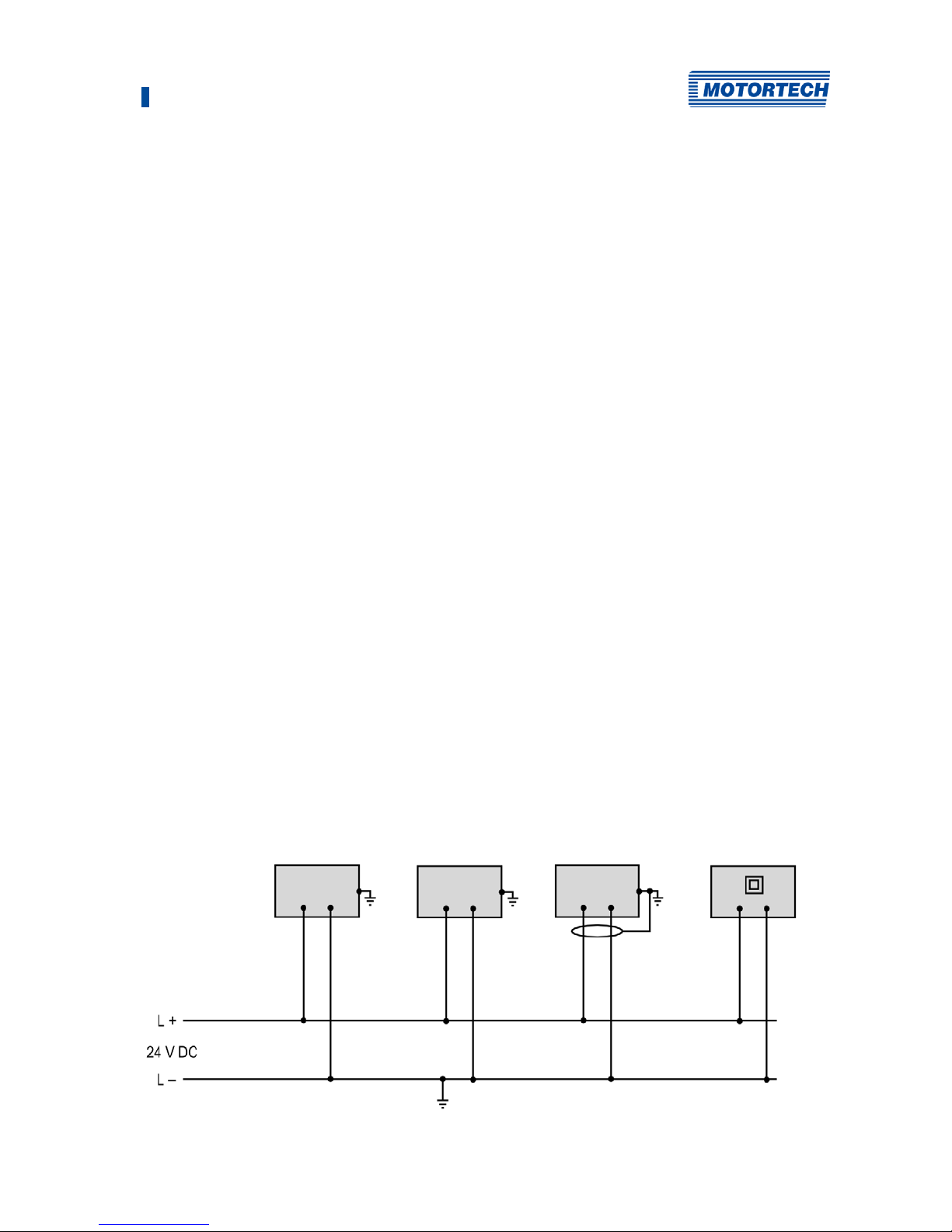
2.3 Information on Electric Isolation
If ground and earth potential are not properly isolated, the following problems as well as others
can occur:
– Electromagnetic interferences (e.g. ground loops)
– Signal corruption (e.g. of the analog voltage signal)
– Unwanted leakage currents
Therefore, earth potential and the negative pole of the power supply of all devices in the electric
assembly that provide the option, should be connected separately. If possible, the negative pole
of the power supply should only be connected to earth potential at one point in the entire
system.
Wiring Example
Device with
shielded wires
Device featuring
protection class II
2 Safety Instructions
10 Rev. 08/2018
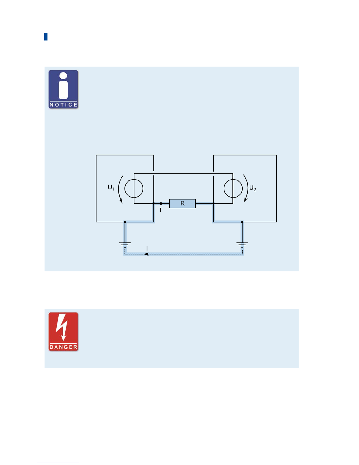
Occurrence of ground loops
The devices shown in the following image do not feature the possibility to
connect the earth potential and the negative pole of the power supply
separated from each other. How ground loops are created.
A ground loop is a ground connection of an electric wiring assembly that is
closed as a loop. Due to impedance (resistance R > ) of the loop, lowfrequency interference currents can lead to an unwanted voltage drop in the
signal path.
Device 1 Device 2
Ground loop
2.4 Special Safety Instructions for the Device
Gas! Danger to life!
Leaking gas may cause death or serious health damage if inhaled. Upon
completion of all assembly works, always check the system's tightness.
When operating a VariFuel2, make sure that the gauge ports are closed.
All works involving gas-carrying parts must be executed by trained
personnel only.
2 Safety Instructions
Rev. 08/2018 11
Explosion hazard!
If the system is not entirely tight and sealed, gas may escape and result in
explosion hazard. Upon completion of all assembly works, always check the
system's tightness. The formation of explosive gases in the area of the
device must be prevented, e.g. by adequate ventilation or the use of gas
sensors which switch off the gas supply.
All works involving gas-carrying parts must be executed by trained
personnel only.
Explosion hazard!
Do not disconnect any connectors while the system is live. If the system is
located in a hazardous area, there is a risk of explosion.
Operational safety!
All screws of the connectors must be adequately tightened.
Risk of destruction due to electrostatic discharge!
The VariStep3 stepper motor driver may only be installed by specialized
personnel who has been trained in handling ESD sensitive components and
with due regard to relevant ESD standards. It must be installed into a
control cabinet, and it must comply with the ESD standard DIN EN 61340-51; VDE 0300-5-1:2008-07.
Damage caused by electrostatic discharge is not covered by warranty.
Risk of burning!
The surfaces of the system may heat up to high temperatures. Ensure good
heat transfer through ventilation when installing in the control cabinet.

2 Safety Instructions
12 Rev. 08/2018
2.5 Proper Disposal
After the expiration of its service life, MOTORTECH equipment can be disposed of with other
commercial waste, or it may be returned to MOTORTECH. We will ensure its environmentally
friendly disposal.

Rev. 08/2018 13
3.1 Functional Description
The VariStep3 stepper motor driver drives the stepper motor of a gas mixer or throttle. This
stepper motor carries out position changes:
– The stepper motor adjusts the openings for the gas supply of the gas mixer and thereby
alters the composition of the gas-air mix.
– In the throttles the stepper motor changes the opening angle of the throttle and thereby
controls the supply of the gas-air mix.
Control can be manual or automatic. Manual adjustments can be made using buttons on the
stepper motor driver via a connected PC. In automatic mode, binary or analog input signals, such
as those provided by a master control, are analyzed. In addition, a connection via CAN bus and
Modbus is possible.
The stepper motor driver is configured using a connected PC. The software used for this purpose
is also used to display current system data and error messages.
3.2 Applications
The VariStep3 stepper motor driver can be used for the following MOTORTECH devices:
– Gas mixer with stepper motor (e.g. VariFuel2)
– ITB throttles with integrated stepper motor
– TG throttle drives
If several devices which are to be controlled via the VariStep3 stepper motor driver are to be
used in one system, several stepper motor drivers are needed. An additional splitter is not
necessary.
Any use other than the one described in the operating manual shall be considered improper use
and will result in the voiding of all warranties.
3 Intended Use
3 Intended Use
14 Rev. 08/2018
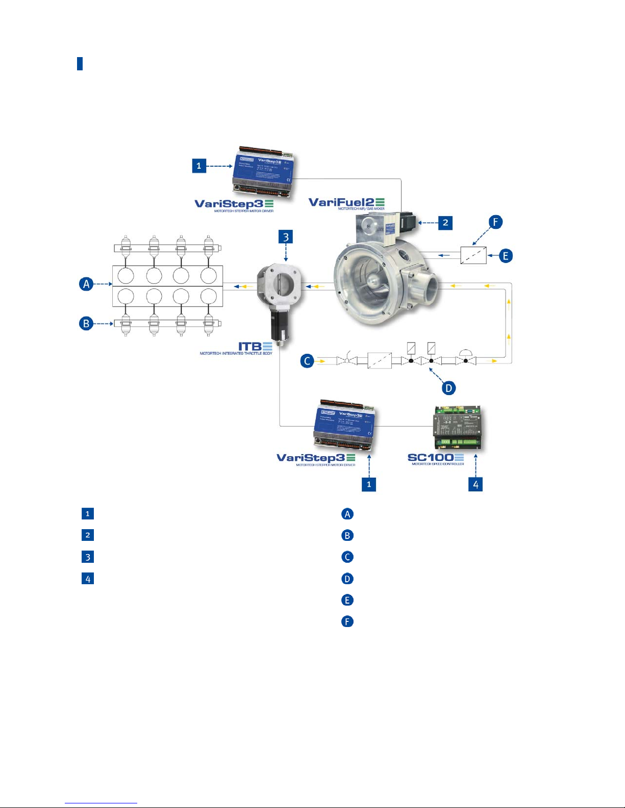
System Overview (Example)
VariStep3 stepper motor drivers
Engine
VariFuel2 gas mixer
Wiring rail (ignition)
ITB throttle with integrated stepper motor
Gas supply
SC100 speed control
Gas train
Air supply
Air filter

Rev. 08/2018 15
4.1 Technical Data
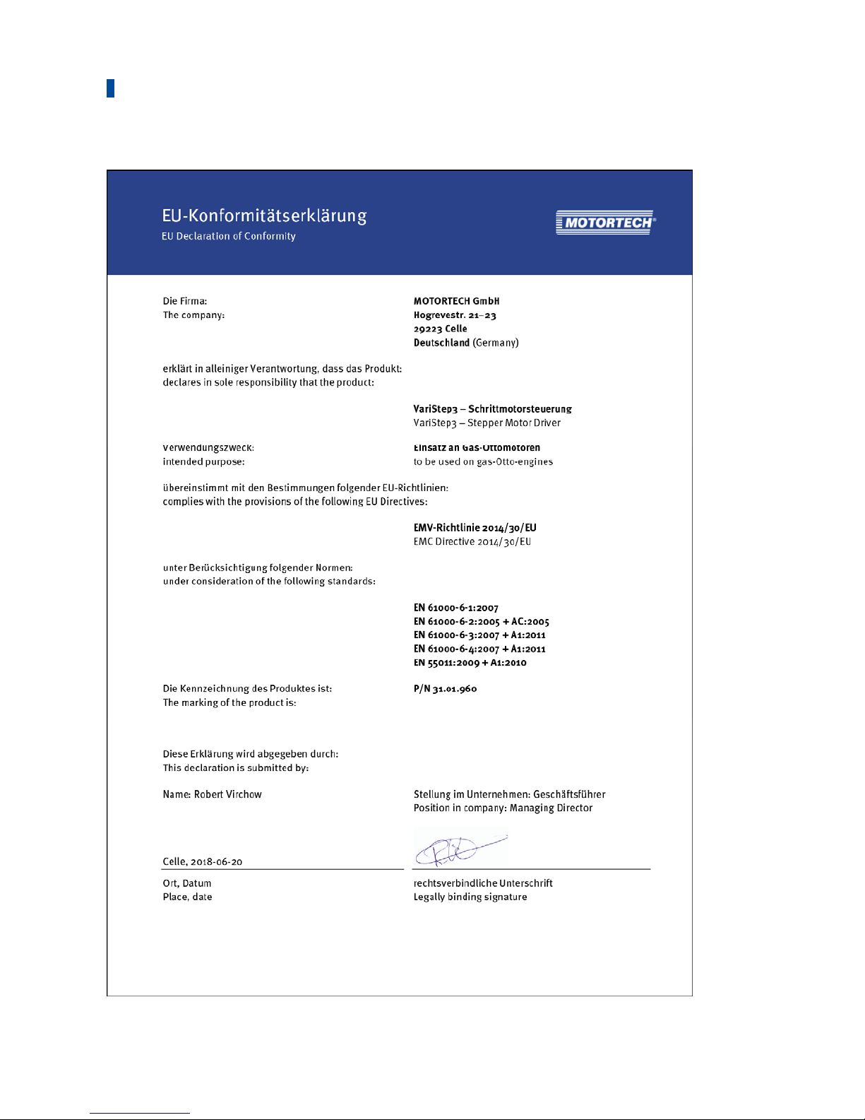
4.1.1 Certifications
The stepper motor driver is certified in accordance with the following standards:
CE
– EMC Directive
– EN 61000-6-1:2007 – Electromagnetic compatibility (EMC). Generic standards; Immunity
for residential, commercial and light-industrial environments
– EN 61000-6-2:2005 + AC:2005 – Electromagnetic compatibility (EMC). Generic
standards. Immunity for industrial environments
– EN 61000-6-3:2007 + A1:2011 – Electromagnetic compatibility (EMC). Generic standards.
Emission standard for residential, commercial and light-industrial environments
– EN 61000-6-4:2007 + A1:2011 – Electromagnetic compatibility (EMC). Generic standards.
Emission standard for industrial environments
– EN 55011:2009 + A1:2010 – Industrial, scientific and medical equipment. Radio-
frequency disturbance characteristics. Limits and methods of measurement
4 Product Description
4 Product Description
16 Rev. 08/2018

4 Product Description
Rev. 08/2018 17
4.1.2 Mechanical Data
The stepper motor driver has the following mechanical characteristics:
Feature Value
Dimensions 160 mm x 126 mm x 61 mm (6.30" x 4.96" x 2.40")
(length x width x height)
Weight 655 g (1.5 lbs)
Shape of device See chapter Overview Drawings on page 21
Mechanical environmental
conditions
Protection: IP20
Climatic environmental
conditions
-20 °C to +60 °C (-4 °F to +140 °F)
Max. 85 % humidity without condensation
up to 2000 m (6561') above sea level
4.1.3 Warning Notices on the Device
Top of Device
WARNING! Read and understand the installation and operating manual prior to installing or
making any adjustments. Do not disconnect equipment unless power has been switched off.
4 Product Description
18 Rev. 08/2018
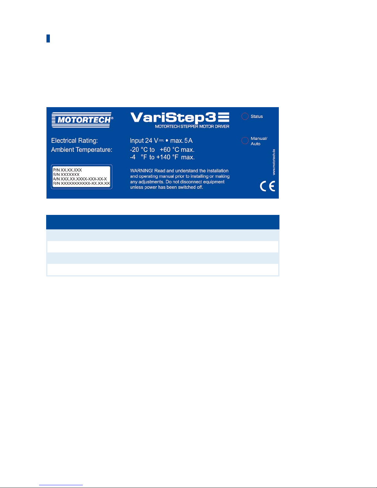
4.1.4 Product Identification – Labeling on the Device
The numbers required for unique product identification are on the device:
Top of Device
Abb. Meaning
P/N Part number of the stepper motor driver
S/N Serial number of the stepper motor driver
A/N Arrangement number of the stepper motor driver
R/N Revision number of the stepper motor driver

4 Product Description
Rev. 08/2018 19
4.1.5 Electrical Data
The stepper motor driver has the following electrical characteristics:
Feature Value
Power consumption max. 60 W
Power supply Nominal voltage: 24 V DC
Operating voltage: 18 V DC to 32 V DC
Required current max. 5.0 A
Electrical Data for Inputs and Outputs
The inputs and outputs of the stepper motor driver have the following electrical data:
Inputs and outputs Values/characteristics
Binary inputs – Galvanically isolated
– Input voltage up to 32 V DC
– Input current at least 5 mA for high level
– Save low level:
Voltages below 1.0 V DC for at least 70 μs
– Save high level:
Voltages above 4.5 V DC for at least 5 μs
Diagram of the Signal
When the reset signal is given, the high level must be present
at the relevant input for at least 50 ms before it is possible to
initiate the reset.

4 Product Description
20 Rev. 08/2018
Inputs and outputs Values/characteristics
Binary outputs – Galvanically isolated
– Inactive: output is high-impedance
– Active: output is low-impedance
– Switching voltage: max. 32 V
– Current: max. 100 mA
– Max. voltage drop at 100 mA: 2.5 V
Analog voltage input Permissible voltage: 0 V to 10 V
Input resistance: 12.4 kΩ
Analog current input Permissible current: 0 mA to 20 mA
Max. difference in potential relative to device ground: +3.5 V
Input resistance: max. 25 Ω
Analog voltage output Output voltage: 0 V to 10 V
Working resistance: min. 500 Ω
Analog current output Output current: 0 mA to 20 mA
Working resistance: max. 500 Ω
4.1.6 Interfaces
USB
– Compatible with USB 1.1 and USB 2.0
– The connector type B is only suitable for temporary data exchange and not for a permanent
connection.
CAN Bus 2.0B Interface
– As per ISO 11898, up to 1 Mbit/s
– Transient-proof (automotive classification)
– Max. 110 participants
Modbus Interface
– RS485 standard
– Max. 32 participants
– Full duplex (4-pole) or half duplex (2-pole)
4 Product Description
Rev. 08/2018 21
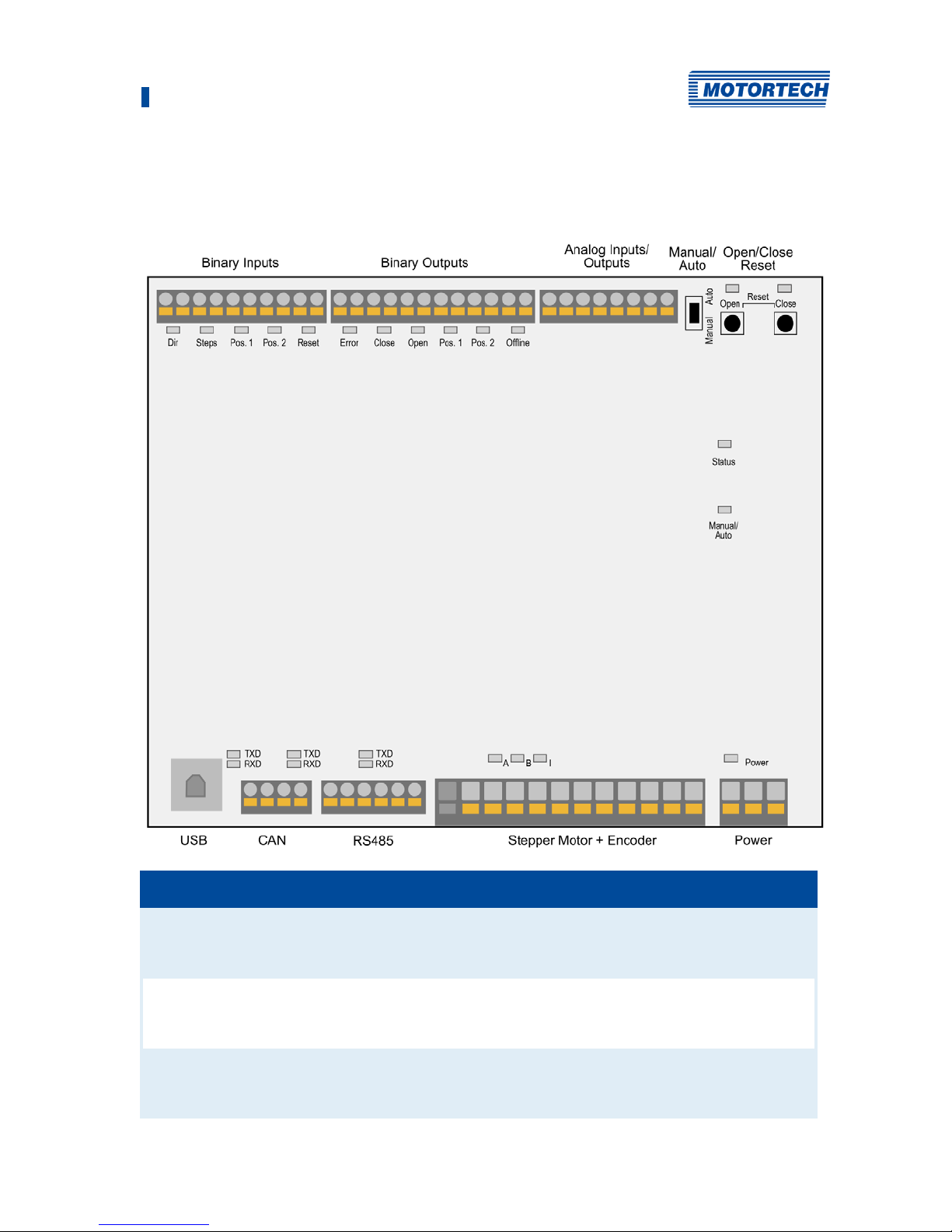
4.1.7 Overview Drawings
Ports/Connections and LEDs
Designation Function
Binary Inputs Binary inputs that are used to change the position of the stepper
motor. In addition, a binary input is available for a reset signal (see
Wiring Binary Inputs on page 30).
Binary Outputs Binary outputs which signal the position of the stepper motor and
the status of the stepper motor driver (see Wiring Binary Outputs on
page 31).
Analog
Inputs/Outputs
Analog inputs and outputs by use of which you can change and
resend the position of the stepper motor (see Wiring Analog Inputs
and Outputs on page 32).

4 Product Description
22 Rev. 08/2018
Designation Function
Manual/Auto (switch) Switch for changing between manual and automatic operation (see
Manual and Automatic Operation on page 36)
Open/Close;
Reset
In manual mode the stepper motor can be driven via the buttons
Open and Close (see Manual and Automatic Operation on page 36).
In the case of an error, the error can be reset followed by a
reference run if you press the two buttons simultaneously.
The Open LED and the Close LED are flashing when the stepper
motor is moved into the corresponding direction via the buttons.
When a stop has been reached, the corresponding LED lights up
permanently.
Status
Y
ou can find details about status signaling in the following
information box.
The LED flashes:
– green: The stepper motor driver is working properly.
– Orange: A warning occurred.
– red: An error occurred.
For additional information on warnings and errors, read section
Runtime Data – Message Log on page 66.
Manual/Auto (LED) The LED lights up:
– green: The stepper motor driver is in automatic mode and is
controlled by the master control.
– Orange: The stepper motor driver is in manual mode.
USB Port for data transmission to the PC. Data transmission is signaled
by the LEDs blinking.
CAN Port for communication via CAN bus with master control. Data
transmission is signaled by the LEDs blinking.
RS485 Port for communication via Modbus with superordinate control
devices. Data transmission is signaled by the LEDs blinking.
Stepper Motor +
Encoder
Port for the stepper motor and the encoder. LEDs A, B and I are
flashing when the stepper motor is moving (see Wiring Stepper
Motor and Encoder on page 28).
Power Connection for the supply voltage (see Wiring Power Supply on
page 27). This LED lights up if the supply voltage is available.

4 Product Description
Rev. 08/2018 23
Status signaling
The status of the VariStep3 stepper motor driver is signaled via the LED
Status.
– Flashing green: Error-free operation
– Flashing orange: Warning
Warnings can be acknowledged by simultaneous pressing of buttons
Open and Close (in manual Mode) or by the external reset signal.
Warnings can for example be caused by:
– Overload of the device
In addition, the LED flashes orange for the following reasons.
– No device type has been configured (device type: None or
Unknown).
– Device connected was changed.
– Overtemperature or over current error confirmed by MICT.
– A reference run is required.
The first two cases make downloading a modified configuration to the
device a priority.
– Flashing red: Error
Errors can be acknowledged by simultaneous pressing of buttons Open
and Close or by the external reset signal. Errors can for example be
caused by:
– Step loss
– Overtemperature
– Low voltage
– Over current
– Alternate flashing of red and green:
The supply voltage for the device was too low during start up.

24 Rev. 08/2018
5.1 Installation Instructions
Unpack the stepper motor driver without damaging it and ensure that the operating manual is
always within reach of the device and easily accessible. Installation locations where strong
vibrations or ambient temperatures of below -20 °C (-4 °F) or above +60 °C (+140 °F) are present
are not permissible and result in the warranty being voided.
Risk of destruction!
The device must not be installed directly on or at the engine, as vibration
and heat may cause damage to electronic components.
Risk of destruction!
Make sure that the device is not covered and ensure sufficient circulation of
air.
Risk of destruction due to electrostatic discharge!
The VariStep3 stepper motor driver may only be installed by specialized
personnel who has been trained in handling ESD sensitive components and
with due regard to relevant ESD standards. It must be installed into a
control cabinet, and it must comply with the ESD standard DIN EN 61340-51; VDE 0300-5-1:2008-07.
Damage caused by electrostatic discharge is not covered by warranty.
Scope of Supply
The supply scope of the VariStep3 stepper motor driver consists of the following components:
– VariStep3 stepper motor driver
– Storage device (USB flash drive or CD-ROM) including configuration software MICT
– USB cable
– Operating manual
Installation of the VariStep3 stepper motor driver
1. Install the VariStep3 stepper motor driver on a horizontal DIN rail in the control cabinet.
5 Installation Instructions

Rev. 08/2018 25
Risk of damage to the device!
Incorrectly installed wiring can cause damage to the device. Please adhere
to the following points:
– Do not disconnect connectors under load. This can cause an arc.
– Use the prescribed wire cross sections and suitable wire end ferrules.
Wiring of components
If you are not using wiring harnesses manufactured by MOTORTECH, carry
out the wiring according to the following specifications:
– Power supply:
3-wire cable, min. conductor cross-section 0.75 mm², max. cable length
10 m (32')
If the cable length is longer, a respective larger cross-section must be
selected.
– Stepper motor:
4-wire, shielded cable, min. conductor cross-section 1.5 mm², max.
cable length 30 m (98')
– Encoder:
5-wire, shielded cable, min. conductor cross-section 0.2 mm², max.
cable length 30 m (98')
– Binary inputs and outputs:
multicore cable, min. conductor cross-section 0.2 mm², max. cable
length 30 m (98')
– Analog inputs and outputs:
multicore, shielded cable, min. conductor cross-section 0.2 mm², max.
cable length 30 m (98')
– CAN bus:
2-pair, shielded bus cable, min. conductor cross-section 0.34 mm²,
max. cable length 250 m (820')
– Modbus:
3-pair, shielded bus cable, min. conductor cross-section 0.25 mm²,
max. cable length 250 m (820')
6 Wiring of the Device

6 Wiring of the Device
26 Rev. 08/2018
Replacing VariStep and VariStep3
Pin assignment of connectors is identical for the VariStep and VariStep3
stepper motor drivers except for the connector Analog Inputs/Outputs. The
identical plugs can simply be plugged from the old device into the new
device. This also applies to CAN and Modbus (RS485) interfaces.
The socket for the stepper motor and encoder for the VariStep3 stepper
motor driver has 12 poles. However, the 11-pole plug can still be used. It just
needs to be plugged in at the far right. Pin 0 of the socket is currently not in
use and therefore locked.
When changing the plug for the power supply, be aware that Earth and
negative pole (–) must be connected separately on the VariStep3.
6 Wiring of the Device
Rev. 08/2018 27
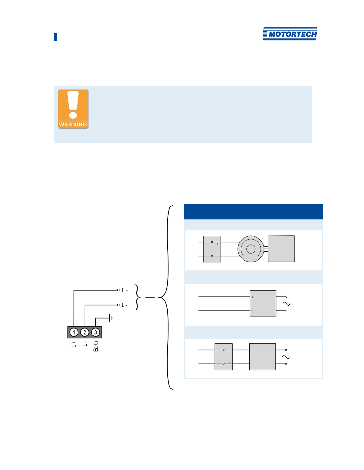
6.1 Wiring Power Supply
Risk of injury!
The stepper motor may be started unintentionally when the supply voltage
is applied. Especially if a throttle is connected, there is a risk of fingers or
other body parts being trapped or squashed. Therefore, work on the
connected devices (throttle or gas mixer) must always be carried out with
disconnected supply voltage.
The power supply is wired using the 3-pole plug. In order to comply with the EMC requirements,
it is absolutely necessary that the earth contact is connected with a wire separate from the
negative pole (L -).
L≙ 18 V DC to 32 V DC (nominal voltage: 24 V DC)
Variations
1 Battery Generator Control Unit
2
Power supply
3
Battery Charger

6 Wiring of the Device
28 Rev. 08/2018
6.2 Wiring Stepper Motor and Encoder
Risk of destruction!
To rule out the possibility of moving the devices connected out of the
control area, observe the following procedure when connecting the stepper
motor to the VariStep3 stepper motor driver:
1. Configure the VariStep3 stepper motor driver for your device type (see
section External Device on page 53.
2. Separate the stepper motor driver from the power supply.
3. Connect the stepper motor of the VariFuel2 air/gas mixer or the throttle
to the stepper motor driver.
4. Connect the VariStep3 stepper motor driver again to the power supply.
▸ Now, the stepper motor driver will initiate a reference run. The
device is ready for operation.
Assignment of the wire colors
Take the assignment of the wire colors of the wiring harness from the wiring
diagram enclosed with the wiring harness.
Wiring via the 11-pole plug on the stepper motor driver. The socket for the stepper motor and
encoder has 12 poles. The 11-pole plug must be plugged in at the far right. Pin 0 of the socket is
currently not in use and therefore locked. The VariStep3 stepper motor driver has been approved
for residential environments if the wiring of the stepper motor and encoder does have a length of
no more than 10 m (32').
 Loading...