

Motortech Varistep Operating Manual
VARISTEP –
STEPPER MOTOR CARD
OPERATING MANUAL
MOTORTECH Gas Regulation
P/N 01.
5
0.003 – EN | Rev. 07/201
3

Copyright
© Copyright 2013 MOTORTECH GmbH. All rights reserved.
Distribution and reproduction of this publication or parts thereof, regardless of the specific
purpose and form, are not permissible without express written approval by MOTORTECH.
Information contained in this publication may be changed without prior notice.
Trademarks
All trademarks and logos displayed or used in this publication are the property of the respective
entitled person.

Rev. 07/2013 3
1 General Information .................................................................................................... 6
1.1 What Is the Purpose of this Operating Manual? ......................................................... 6
1.2 Who Is this Operating Manual Targeted to? ............................................................... 6
1.3 Which Symbols Are Used in the Operating Manual? ................................................... 6
1.4 Which Abbreviations/Acronyms Are Used in the Operating Manual? ........................... 7
2 Safety Instructions ..................................................................................................... 8
2.1 General Safety Instructions ..................................................................................... 8
2.2 Electrostatic Discharge Hazards .............................................................................. 9
2.3 Special Safety Instructions for the Device ................................................................ 9
2.4 Proper Disposal .................................................................................................... 10
3 Intended Use ............................................................................................................. 11
3.1 Functional Description ........................................................................................... 11
3.2 Applications .......................................................................................................... 11
4 Product Description ................................................................................................... 12
4.1 Technical Data ...................................................................................................... 12
4.1.1 Certifications ..................................................................................................... 12
4.1.2 Mechanical Data ................................................................................................ 14
4.1.3 Warning Notices on the Device ............................................................................ 14
4.1.4 Product Identification – Labeling on the Device .................................................... 15
4.1.5 Electrical Data .................................................................................................... 16
4.1.6 Interfaces .......................................................................................................... 17
4.1.7 Overview Drawings ............................................................................................. 18
5 Installation Instructions .............................................................................................20
5.1 Installation Instructions ........................................................................................ 20
6 Wiring of the Control Unit .......................................................................................... 21
6.1 Wiring Power Supply ............................................................................................. 21
6.2 Wiring Stepper Motor and Encoder ........................................................................ 22
6.3 Wiring Digital Inputs ............................................................................................. 24
6.4 Wiring Digital Outputs .......................................................................................... 25
6.5 Wiring Analog Inputs and Outputs ......................................................................... 26
6.6 Wiring CAN Bus .................................................................................................... 28
6.7 Wiring Modbus ..................................................................................................... 29
7 Functions ................................................................................................................... 31
7.1 Manual and Automatic Operation ........................................................................... 31
7.2 Reference Run ...................................................................................................... 31
TABLE OF
CO
NTENT
S

TABLE OF CONTENTS
4 Rev. 07/2013
7.3 Open/Closed Positions ......................................................................................... 32
7.4 Configurable Opening Angles (Position 1 and 2) ...................................................... 32
7.5 Change of Openings via Digital and Analog Inputs .................................................. 32
7.6 Analysis of Positions via Analog Outputs................................................................ 32
7.7 Access Control ...................................................................................................... 33
8 Settings via the MICT ................................................................................................. 35
8.1 MICT System Requirements ................................................................................... 35
8.2 MICT Installation .................................................................................................. 35
8.3 Access Levels in the MICT ..................................................................................... 36
8.4 Configuration Pages (Overview) ............................................................................ 37
8.5 Menu Bar and Toolbar........................................................................................... 38
8.6 Online Update Settings ........................................................................................ 41
8.7 Access Control of Control Unit ............................................................................... 42
8.7.1 Enabling/Disabling Access Control ..................................................................... 42
8.7.2 Login/Logout .................................................................................................... 43
8.7.3 Changing the PIN ............................................................................................... 43
8.7.4 Resetting all PINs .............................................................................................. 44
8.8 Selecting the Device Type ..................................................................................... 45
8.9 Opening an Existing Configuration File .................................................................. 45
8.10 Configuration ..................................................................................................... 45
8.10.1 External Device ................................................................................................ 46
8.10.2 Inputs / Outputs - Control Setup ....................................................................... 48
8.10.3 Positions – Values ............................................................................................51
8.10.4 Miscellaneous – Communication ...................................................................... 52
8.10.5 Miscellaneous – Service Contact ....................................................................... 54
8.11 Runtime Data ...................................................................................................... 55
8.11.1 Runtime Data – Overview .................................................................................. 56
8.11.2 Runtime Data – Warnings ................................................................................. 58
8.11.3 Runtime Data – Errors ....................................................................................... 59
8.11.4 Runtime Data – Diagnostics .............................................................................. 61
8.11.5 Runtime Data – Information .............................................................................. 63
8.12 Log .................................................................................................................... 64
9 Operation ................................................................................................................. 66
9.1 Firmware Update .................................................................................................. 66
10 Disturbances ............................................................................................................ 70
10.1 Troubleshooting .................................................................................................. 70
10.2 Possible Faults ................................................................................................... 70

Rev. 07/2013 5
10.3 Acknowledging Faults ......................................................................................... 71
10.4 Customer Service Information .............................................................................. 71
10.5 Returning Equipment for Repair / Inspection ......................................................... 72
10.6 Instructions for Packaging the Equipment ............................................................ 72
11 Maintenance ............................................................................................................. 73
11.1 Spare Parts and Accessories ................................................................................. 73
12 Index ....................................................................................................................... 74

6 Rev. 07/2013
Read through this operating manual carefully before use and become familiar with the machine.
Installation and start-up should not be carried out before reading and understanding this
document. Keep this manual readily available so that you can reference it as needed.
1.1 What Is the Purpose of this Operating Manual?
This manual serves as an aid for the installation and operation of the product and supports the
technical staff with all operating and maintenance tasks to be performed. Furthermore, this
manual is aimed at preventing dangers to life and health of the user and third parties.
1.2 Who Is this Operating Manual Targeted to?
The operating manual provides a code of conduct for personnel tasked with the set-up,
operation, maintenance, and repair of gas engines. A certain level of technical knowledge with
respect to the operation of gas engines and basic knowledge of electronic ignition systems are
necessary. Persons who are only authorized to operate the gas engine shall be trained by the
operating company and shall be expressly instructed concerning potential hazards.
1.3 Which Symbols Are Used in the Operating Manual?
The following symbols are used in this manual and must be observed:
Example
This symbol indicates examples, which point out necessary handling steps
and techniques. In addition, you receive additional information from the
examples, which will increase your knowledge.
Notice
This symbol indicates important notices for the user. Follow these. In
addition, this symbol is used for overviews that give you a summary of the
necessary work steps.
Warning
This symbol indicates warnings for possible risks of property damage or
risks to health. Read these warning notices carefully and take the
mentioned precautionary measures.
1 GENERAL INFORMATION
Rev. 07/2013 7
Danger
This symbol indicates warnings for danger to life, especially due to high
voltage. Read these warning notices carefully and take the mentioned
precautionary measures.
1.4 Which Abbreviations/Acronyms Are Used in the Operating Manual?
In the manual or the user interface, the following abbreviations / acronyms are used.
Abb. Term Description Explanation
CAN bus Controller Area
Network Bus
Bus for control
devices / networks
Asynchronous serial
connection system for
networking control devices
CE Conformité
Européenne
Conformity with EU
directives
Mark based on EU legislation
for certain products in
conjunction with product safety
CPU Central Processing
Unit
DC Direct Current
EMC Electromagnetic
Compatibility
Compatibility of electrical or
electronic equipment items
with their surroundings
ESD Electrostatic
Discharge
LED Light Emitting Diode
Light emitting electronic semiconductor
MICT MOTORTECH
Integrated
Configuration Tool
Configuration software for
MOTORTECH control units
USB Universal Serial Bus Serial wiring system to connect
a computer to external
equipment

8 Rev. 07/2013
2.1 General Safety Instructions
MOTORTECH equipment is manufactured as state of the art and therefore safe and reliable to
operate. Nevertheless the equipment can cause risks or damages can occur, if the following
instructions are not complied with:
– The gas engine must only be operated by trained and authorized personnel.
– Operate the equipment only within the parameters specified in the technical data.
– Use the equipment correctly and for its intended use only.
– Never apply force.
– For all work, such as installation, conversion, adaptation, maintenance, and repair, all
equipment must be disconnected from the power supply and secured against unintentional
restarting.
– Perform only such maintenance and repair work as is described in this operating manual,
and follow the instructions given while working. For maintenance of the equipment, only use
spare parts supplied by MOTORTECH. Further work must only be performed by personnel
authorized by MOTORTECH. Non-compliance with the instructions will void any warranties
for the proper function of the equipment as well as the responsibility for the validity of the
certifications.
– Safety devices must not be dismounted or disabled.
– Avoid all activities that can impair the function of the equipment.
– Operate the equipment only while it is in proper condition.
– Investigate all changes detected while operating the gas engine or ignition system.
– Ensure compliance with all laws, directives and regulations applicable to the operation of
your system, including such not expressly stated herein.
– If the system is not entirely tight and sealed, gas may escape and lead to an explosion
hazard. Upon completion of all assembly works, please always check the system's
tightness.
– Always ensure adequate ventilation of the engine compartment.
– Ensure a safe position at the gas engine.
2 SAFETY INSTRUCTIONS
Rev. 07/2013 9
2.2 Electrostatic Discharge Hazards
Electronic equipment is sensitive to static electricity. To protect these components from damage
caused by static electricity, special precautions must be taken to minimize or prevent
electrostatic discharge.
Observe these safety precautions while you work with the equipment or in its vicinity.
– Before performing maintenance or repair work, ensure that the static electricity inherent to
your body is discharged.
– Do not wear clothing made from synthetic materials to prevent static electricity from
building up. Your clothing should therefore be made of cotton or cotton mix materials.
– Keep plastics such as vinyl and Styrofoam materials as far away from the control system, the
modules, and the work environment as possible.
– Do not remove the circuit boards from the housing of the device.
2.3 Special Safety Instructions for the Device
Explosion hazard!
When the system is powered up, do not remove any connectors unless the
system is not located in a potentially explosive atmosphere.
Explosion hazard!
If the system is not entirely tight and sealed, gas may escape and lead to an
explosion hazard. Upon completion of all assembly works, always check the
system's tightness. Also ensure that the gauge port on the VariFuel2 is
closed.
All works involving gas-carrying parts must be executed by trained
personnel only.
Operational safety!
All screws of the connectors must be adequately tightened.

2 SAFETY INSTRUCTIONS
10 Rev. 07/2013
Risk of destruction due to electrostatic discharge!
The VariStep stepper motor card may only be installed by specialized
personnel who has been trained in handling ESD sensitive components and
with due regard to relevant ESD standards. It must be installed into a
control cabinet, and it is necessary to comply with the ESD standard
DIN EN 61340-5-1; VDE 0300-5-1:2008-07.
Damages caused by electrostatic discharge are not covered by the
guarantee.
Risk of burning!
The surfaces of the system may heat up to high temperatures.
Risk of damage!
The stepper motor of the VariFuel2 is not suitable for carrying or lifting a
gas mixer. There is a danger that the stepper motor could break, and if the
gas mixer were to fall, it could result in injury or property damage.
Always carry or lift the gas mixer by its exterior housing.
2.4 Proper Disposal
After the expiration of its service life, MOTORTECH equipment can be disposed of with other
commercial waste, or it may be returned to MOTORTECH. We will ensure its environmentally
friendly disposal.

Rev. 07/2013 11
3.1 Functional Description
The VariStep stepper motor card controls the stepper motor of a VariFuel2 gas mixer. This
stepper motor changes the openings of the fuel ring, thus adapting the composition of the
air/gas mixture.
Control can be manual or automatic. Manual adjustments can be made using buttons on the
stepper motor card or via a connected PC. In automatic mode, digital or analog input signals,
such as those provided by a master control, are analyzed.
The stepper motor card is configured using a connected PC. The software used for this purpose
is also used to display current system data and error messages.
3.2 Applications
The VariStep stepper motor card can be used for all VariFuel2 gas mixers with stepper motors. If
two VariFuel2 gas mixers are being used, two VariStep stepper motor cards are required. An
additional splitter is not necessary.
Any use other than the one described in the operating manual shall be considered improper use
and will result in the voiding of all warranties.
3
INTENDED USE

12 Rev. 07/2013
4.1 Technical Data
4.1.1 Certifications
The stepper motor card is certified in accordance with the following standards:
CE
– EMC Directive 2004/108/EC
– Emission standard for industrial environments as per DIN EN 61000-6-4:2007
– Immunity for industrial environments as per DIN EN 61000-6-2:2006
4
PRODUCT DESCRIPTION

Rev. 07/2013 13
DECLARATION OF CONFORMITY
The company:
MOTORTECH GmbH
Hogrevestrasse 21-23
29223 Celle
declares that the products: VariStep Stepper Motor Card
Intended purpose: to be used on gas-Otto-engines
complies with the provisions of the following EC-Directives:
EMC Directive 2004/108/EC
under consideration of following standards:
DIN EN 61000-6-4:2007
DIN EN 61000-6-2:2006
DIN EN 61000-4-2, DIN EN 61000-4-3
DIN EN 61000-4-4, DIN EN 61000-4-5
DIN EN 61000-4-6, DIN EN 61000-4-8
The marking of the product is: P/N 31.01.955
This declaration is submitted by:
Name: Florian Virchow
Professional status: Managing Director
Celle, 16.02.2011
City, Date
legally binding signature

4 PRODUCT DESCRIPTION
14 Rev. 07/2013
4.1.2 Mechanical Data
The stepper motor card has the following mechanical characteristics:
Feature Value
Dimensions 217 x 128 x 50 mm (8.54 x 5.04 x 1.97 '')
(length x width x height)
Weight 655 g (1.44 lbs)
Shape of device Refer to chapter
Overview Drawing
s
on page 18
Mechanical environmental
conditions
Protection: IP20
Climatic environmental
conditions
-15 °C to 65 °C max. (5 °F to 149 °F)
Max. 85% humidity without condensation
up to 2000 m (6561.68 ') above sea level
4.1.3 Warning Notices on the Device
Top of Device
Warning Meaning
Component subject to electrostatic hazards
WARNING: Read and understand the
operation manual prior to installing or
making any adjustments. Do not disconnect
equipment unless power has been switched
off.
Rev. 07/2013 15
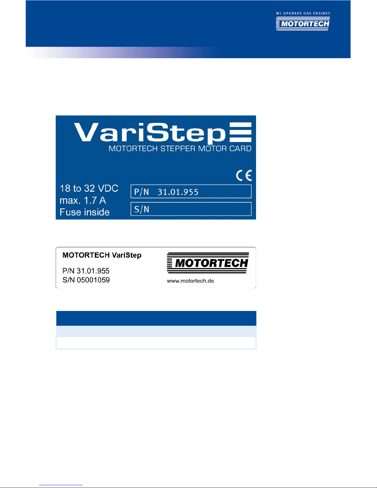
4.1.4 Product Identification – Labeling on the Device
The numbers required for unique product identification are on the device:
Top of Device
Bottom of Device
Abb. Meaning
P/N Control unit product number
S/N Control unit serial number
4 PRODUCT DESCRIPTION
16 Rev. 07/2013
4.1.5 Electrical Data
The stepper motor card has the following electrical characteristics:
Feature Value
Power consumption Max. 31 W
Power
supply
18 to 32 V DC
Required current Max. 1.7 A
Internal fuse 3.15 A, delay, 5x20 mm, exchangeable
Electrical Data for Inputs and Outputs
The inputs and outputs of the stepper motor card have the following electrical data:
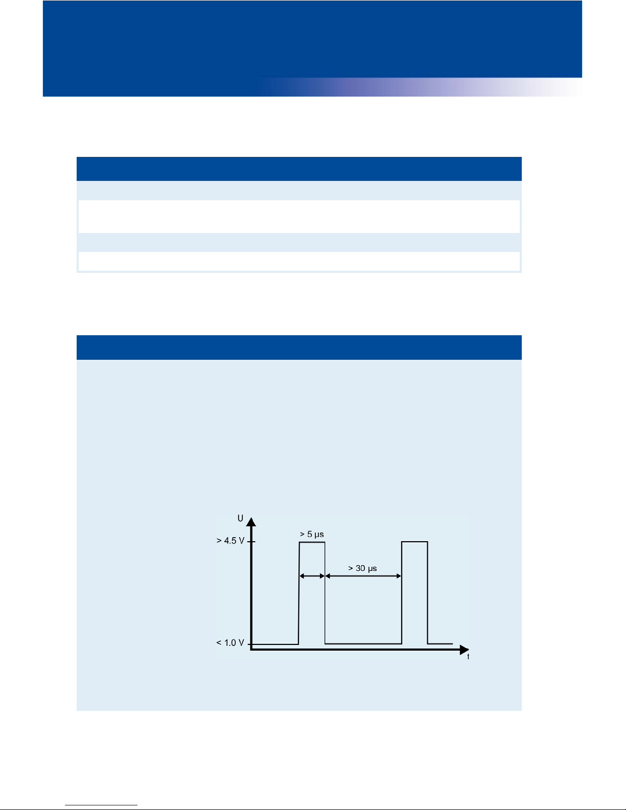
Inputs and outputs Values/characteristics
Digital inputs – Galvanically isolated
– Input voltage up to 32 V DC
– Input current at least 5 mA for high level
– Save low level:
voltages below 1.0 V DC for at least 30 μs
– Save high level:
voltages above 4.5 V DC for at least 5 μs
Diagram of the signal
When the reset signal is given, the high-level must be present
at the relevant input for at least 50 ms before it is possible to
initiate the reset.

Rev. 07/2013 17
Inputs and outputs Values/characteristics
Digital outputs – Galvanically isolated
– Low level: output is high-impedance
– High level: output is low-impedance
– Switching voltage: maximum 32 V
– Current: maximum 500 mA
Analog voltage input (
Ui
n
) Permissible voltage: 0 to 10 V
Input resistance: 12.4 kΩ
Analog current input (
Ii
n
) Permissible current: 0 to 20 mA
Max. difference in potential relative to device ground: +/-15 V
Input resistance: 10 Ω
Analog voltage output
(
Uout
)
Output voltage: 0 to 10 V
Working resistance: min. 300 Ω
Analog current output
(
Iout
)
Output current: 0 to 20 mA
Working resistance: max. 300 Ω
4.1.6 Interfaces
USB
– Compatible with USB 1.1 and USB 2.0
– The connector B version is only suitable for temporary data exchange and not for a
permanent connection.
CAN Bus 2.0B Interface (currently not yet available)
– As per ISO 11898, up to 1 MBit/s
– Transient-proof (automotive classification)
– Max. 110 participants
Modbus Interface (currently not yet available)
– RS485 standard
– Max. 32 participants
– Full duplex (4-pole) or half duplex (2-pole)
4 PRODUCT DESCRIPTION
18 Rev. 07/2013
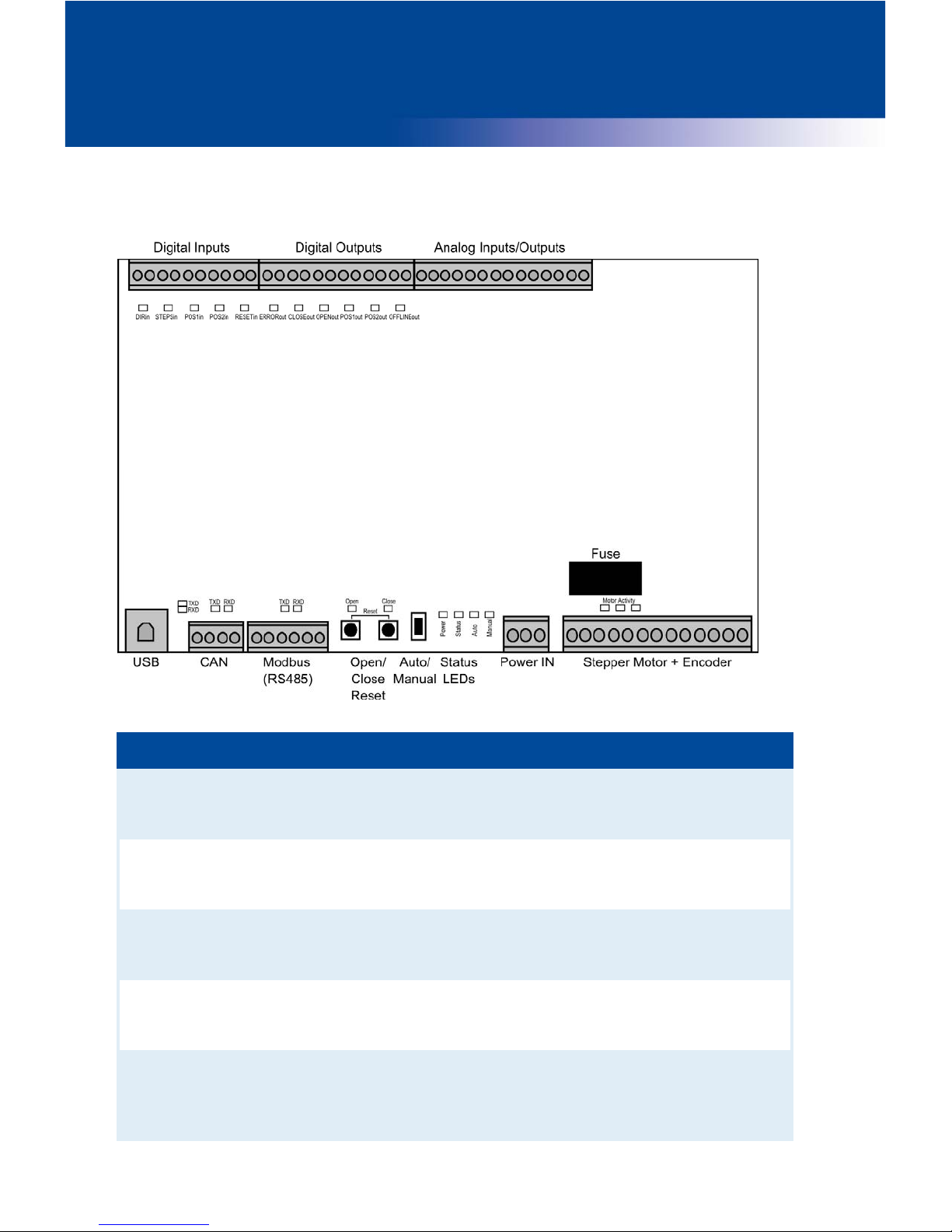
4.1.7 Overview Drawings
Ports/Connections and LEDs
Designation Function
Digital Inputs Digital inputs via which the fuel ring opening can be modified.
There is also a digital input available for a reset signal (refer to
Wiring Digital Inputs
on page 24).
Digital Outputs Digital outputs that signal the position of the stepper motor and the
status of the stepper motor card (refer to
Wiring Digital Outputs
on
page 25).
Analog
Inputs/Outputs
Analog inputs and outputs that are used to modify and return the
position of the stepper motor (refer to
Wiring Analog Inputs and
Outputs
on page 26).
USB Port for the data transmission to the PC. The data transfer is
signaled by means of the LEDs
TXD
and
RXD (TXD
=data being sent,
RXD
=data being received).
CAN
(not yet available)
Port for communication via CAN bus with master control devices
(such as ALL-IN-ONE). The data transfer is signaled by means of the
LEDs
TXD
and
RXD (TXD
=data being sent,
RXD
=data being
received).

Rev. 07/2013 19
Designation Function
Modbus (RS485)
(not yet available)
Port for communication via Modbus with master control devices.
The data transfer is signaled by means of the LEDs
TXD
and
RXD
(
TXD
=data being sent,
RXD
=data being received).
Open/Close;
Reset
The
Ope
n
and
Clos
e
buttons can be used to control the stepper
motor in manual mode (refer to
Manual and Automatic Operation
on
page 31). In the case of an error, the error can be reset followed by a
reference run if you press the two buttons simultaneously.
Auto/Manual Switch used to change between manual and automatic mode (see
Manual and Automatic Operation
on page 31)
Status LEDs –
Powe
r
This LED lights up if there is a sufficient supply voltage present.
–
Status
This LED flashes green if the stepper motor card is working
without any problems. If an error has occurred, this LED will
flash orange (refer to
Runtime Data – Errors
on page 59).
–
Auto
This LED lights up if the stepper motor card is in automatic
mode and is controlled by the signals of the master control.
–
Manual
This LED lights up if the stepper motor card is in manual mode.
Power IN Connection for the supply voltage (refer to
Wiring Power Suppl
y
on
page 21)
Stepper Motor +
Encoder
Port for the stepper motor and the encoder. The
Motor Activit
y
LEDs
flash whenever the stepper motor moves (refer to
Wiring Stepper
Motor and Encoder
on page 22).
Fuse Replaceable fuse (3.15 A)

20 Rev. 07/2013
5.1 Installation Instructions
Unpack the stepper motor without damaging it and ensure that the operating manual is always
within reach of the device and easily accessible. Installation locations where strong vibrations
or ambient temperatures of below -15 °C (5 °F) or above 65 °C (149 °F) are present are not
permissible and result in the warranty being voided.
Risk of damage!
The device must not be installed directly on or at the engine, as vibration
and heat may cause damage to electronic components.
Risk of damage!
Please make sure that the device is not covered and ensure sufficient
circulation of air.
Risk of destruction due to electrostatic discharge!
The VariStep stepper motor card may only be installed by specialized
personnel who has been trained in handling ESD sensitive components and
with due regard to relevant ESD standards. It must be installed into a
control cabinet, and it is necessary to comply with the ESD standard
DIN EN 61340-5-1; VDE 0300-5-1:2008-07.
Damages caused by electrostatic discharge are not covered by the
guarantee.
Scope of Supply
The VariStep stepper motor card as supplied consists of the following components:
– VariStep stepper motor card
– CD-ROM
– USB cable
– Operating manual
Assembly of Control Unit
1. Please install the control unit on the DIN-rail in the control cabinet.
2. Please fix the card using the attachment screws on the sides.
5
INSTALLATION INSTRUCTIONS
Rev. 07/2013 21
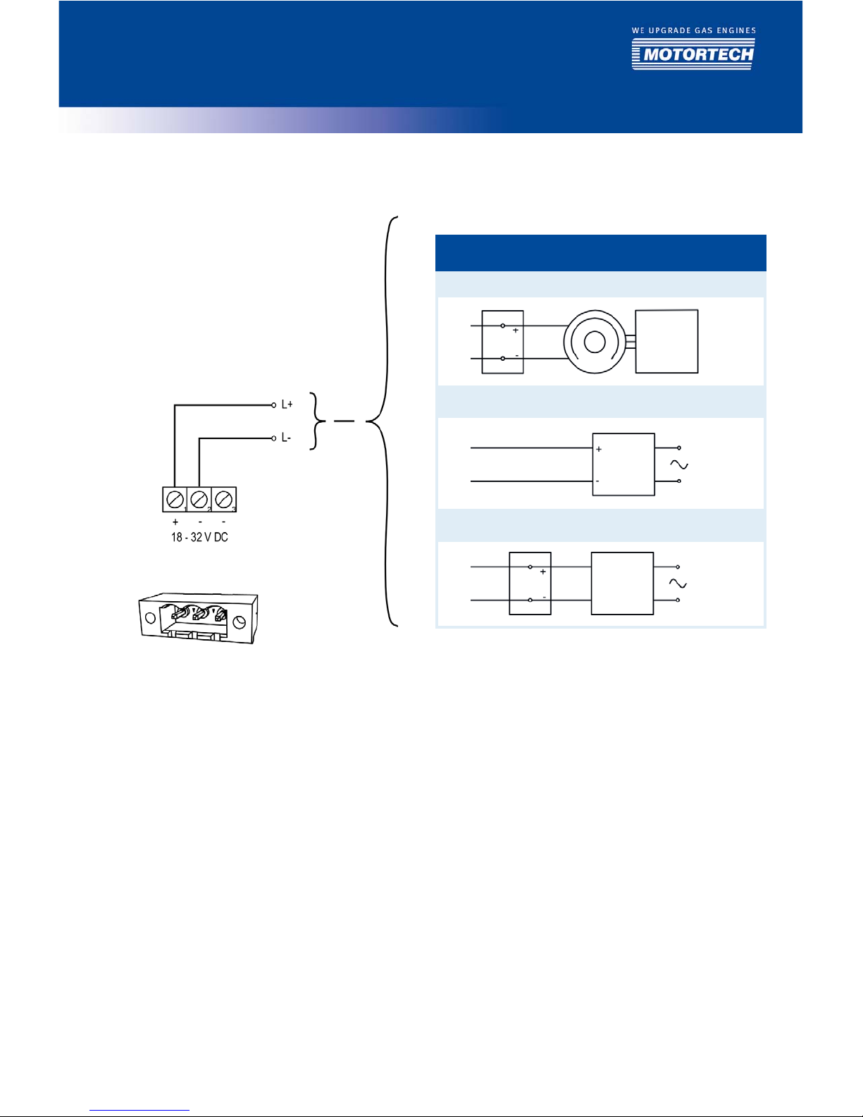
6.1 Wiring Power Supply
The power supply is wired using the 3-pole plug.
Variations
1 Battery Generator Control unit
2
Supply voltage
3
Battery Charger
6 WIRING OF THE CONTROL UNIT
6 WIRING OF THE CONTROL UNIT
22 Rev. 07/2013
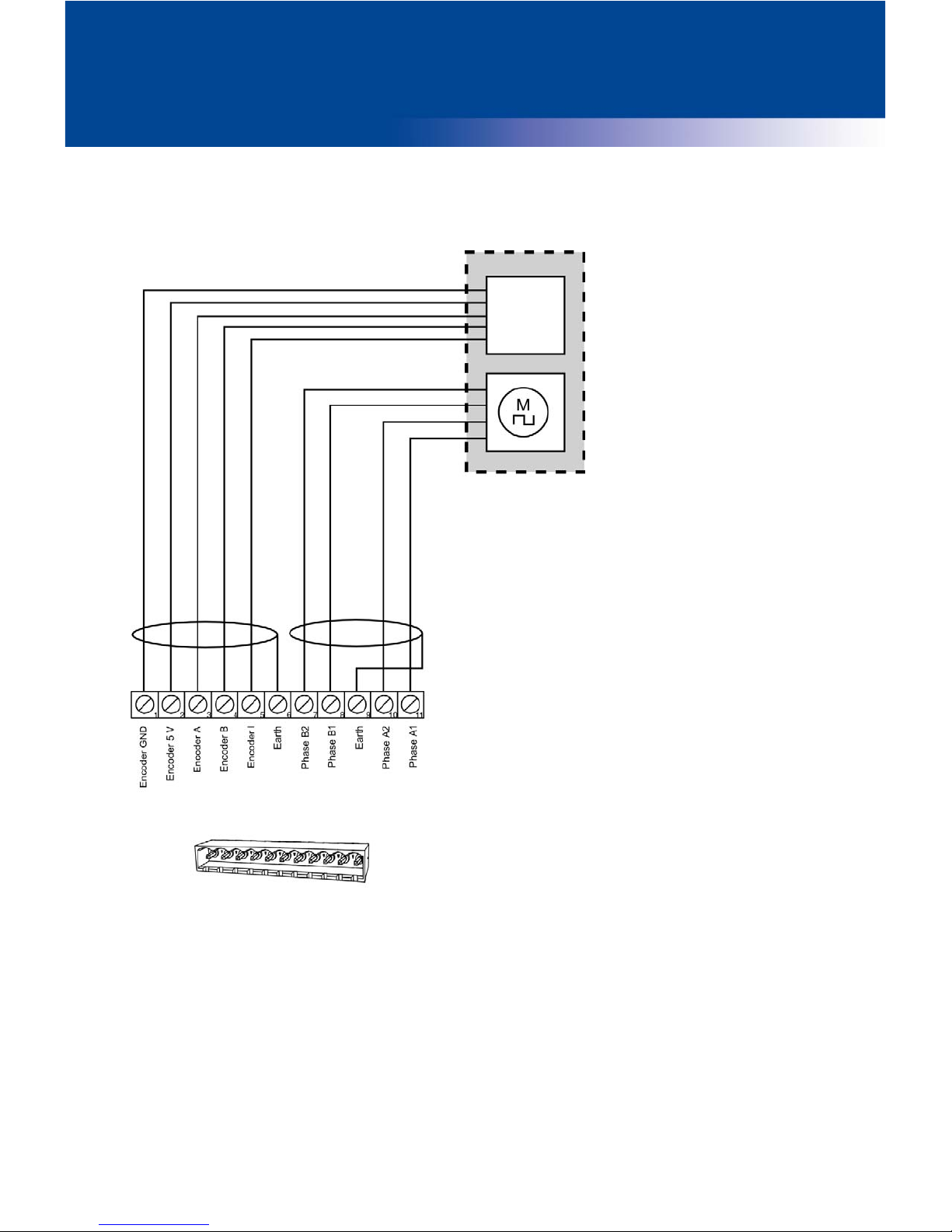
6.2 Wiring Stepper Motor and Encoder
Wiring via the 11-pole plug on the stepper motor card. The length of the connecting cable must
not exceed 10 m (32.8 ft).
Encoder
Stepper motor

Rev. 07/2013 23
Pin assignment when using the original MOTORTECH wiring harness:
Pin stepper motor
card
Description
Pin stepper
motor and
encoder
Wire color/
designation
1 Encoder ground
J
Brown
2 Encoder 5V
supply voltage
I
Y
ellow
3 Encoder A E White
4 Encoder B F Green
5 Encoder I (index) G Grey
6 Encoder earth H Shield
7 Stepper motor phase B2 D 4
8 Stepper motor phase B1 C 3
9 Stepper motor earth H Shield
10 Stepper motor phase A2 B 2
11 Stepper motor phase A1 A 1
 Loading...