

Motortech DetCon, DetCon20, DetCon2 Operating Manual
DetCon –Detonation Controller
Operating Manual
P/N 01.30.002 | Rev. 02/2019

Original instructions
Copyright
© Copyright 2019 MOTORTECH GmbH. All rights reserved.
Distribution and reproduction of this publication or parts thereof, regardless of the specific
purpose and form, are not permissible without express written approval by MOTORTECH.
Information contained in this publication may be changed without prior notice.
Trademarks
MOTORTECH products and the MOTORTECH logo are registered and/or common law trademarks
of the MOTORTECH GmbH. All further trademarks and logos displayed or used in this publication
are the property of the respective entitled person.

Rev. 02/2019 3
1 General Information .................................................................................................... 6
1.1 What Is the Purpose of this Operating Manual? ......................................................... 6
1.2 Who Is this Operating Manual Targeted to? ............................................................... 6
1.3 Which Symbols Are Used in the Operating Manual? ................................................... 6
1.4 Which Abbreviations/Acronyms Are Used in the Operating Manual? ........................... 7
2 Safety Instructions ..................................................................................................... 9
2.1 General Safety Instructions ..................................................................................... 9
2.2 Electrostatic Discharge Hazards ............................................................................ 10
2.3 Special Safety Instructions for the Device ............................................................... 11
2.4 Proper Disposal .................................................................................................... 12
3 Intended Use ............................................................................................................. 13
3.1 Functional Description .......................................................................................... 13
3.2 Applications ......................................................................................................... 17
3.3 Application in hazardous areas ............................................................................. 17
3.3.1 USA, Canada ...................................................................................................... 17
3.3.2 European Union ................................................................................................. 18
4 Product Description ...................................................................................................20
4.1 Technical Data ...................................................................................................... 20
4.1.1 Certifications ..................................................................................................... 20
4.1.2 Mechanical Data ................................................................................................ 28
4.1.3 Warning Notices on the Device ............................................................................ 29
4.1.4 Product Identification - Labels on the Device ........................................................ 30
4.1.5 Electrical Data .................................................................................................... 31
4.1.6 Interfaces .......................................................................................................... 32
4.1.7 Technical Data of the Detonation Sensors ............................................................ 32
4.1.8 Technical Data of the Ignition Sensor Unit (ISU) ................................................... 34
4.1.9 Technical Data of the Camshaft Sensor ................................................................ 34
4.1.10 Requirements for External Equipment ................................................................ 35
4.1.11 Overview Drawings ........................................................................................... 35
5 Installation Instructions ............................................................................................. 41
5.1 Ground Connection / Protective Conductor Connection on ATEX Enclosure ................ 43
5.2 Lead bushings through the enclosure wall on the ATEX enclosure ............................ 45
5.3 Mounting the Detonation Sensors .......................................................................... 49
5.4 Mounting the Ignition Sensor Unit (ISU) ................................................................. 54
5.5 Mounting the Camshaft Sensor .............................................................................. 56
Table of Contents

Table of Contents
4 Rev. 02/2019
6 Wiring of the Device ................................................................................................... 57
6.1 Wiring of the Detonation Sensors .......................................................................... 57
6.2 Wiring for Ignition Controller with ASO Output ....................................................... 58
6.3 Wiring of the Ignition Sensor Unit (ISU) .................................................................. 60
6.4 Wiring of the Camshaft Sensor (for Diesel and Pilot Injection Engines Only) ............. 62
6.5 Wiring of the Binary Outputs ................................................................................. 64
6.6 Wiring of the Analog Outputs for Ignition Timing Reduction ..................................... 65
6.7 Wiring CAN Bus .................................................................................................... 66
7 Functions ................................................................................................................... 67
7.1 Ignition Timing Reduction ...................................................................................... 67
7.2 Load Reduction .................................................................................................... 67
7.3 Engine Stop ......................................................................................................... 67
8 DenEdit Settings ....................................................................................................... 68
8.1 DenEdit System Requirements ............................................................................... 68
8.2 Installation and First Steps in DenEdit ................................................................... 69
8.3 User Interface Overview ........................................................................................ 72
8.4 Menu Bar and Toolbar .......................................................................................... 73
8.5 Display Area of the Analog Output Signal and the Knocking Intensity ....................... 74
8.6 Error and Status Displays ..................................................................................... 74
8.7 Tabs for Process Monitoring .................................................................................. 76
8.7.1 Tab: Actual Knocking Values ............................................................................... 76
8.7.2 Tab: Knocking History ........................................................................................ 77
8.8 Tabs for the Process Parameters ........................................................................... 77
8.8.1 Tab: Mode ......................................................................................................... 78
8.8.2 Tab: Knocking Params ....................................................................................... 79
8.8.3 Tab: Input Gains ................................................................................................ 80
8.8.4 Tab: Firing Sequence ......................................................................................... 80
8.8.5 Tab: Output Options .......................................................................................... 81
8.8.6 Tab: CAN Params ............................................................................................... 82
8.9 Status Bar ........................................................................................................... 83
9 Operation ................................................................................................................. 84
9.1 Start-up ............................................................................................................... 84
9.2 Shutdown ............................................................................................................ 84

Table of Contents
Rev. 02/2019 5
10 Disturbances ............................................................................................................ 85
11 Maintenance ............................................................................................................ 86
11.1 Spare Parts and Accessories ................................................................................. 86
12 Index ....................................................................................................................... 87
6 Rev. 02/2019
Read through this operating manual carefully before use and become familiar with the product.
Installation and start-up should not be carried out before reading and understanding this
document. Keep this manual readily available so that you can reference it as needed.
1.1 What Is the Purpose of this Operating Manual?
This manual serves as an aid for the installation and operation of the product and supports the
technical staff with all operating and maintenance tasks to be performed. Furthermore, this
manual is aimed at preventing dangers to life and health of the user and third parties.
1.2 Who Is this Operating Manual Targeted to?
The operating manual provides a code of conduct for personnel tasked with the setup,
operation, maintenance, and repair of gas engines. A certain level of technical knowledge with
respect to the operation of gas engines and basic knowledge of electronic ignition systems are
necessary. Persons who are only authorized to operate the gas engine shall be trained by the
operating company and shall be expressly instructed concerning potential hazards.
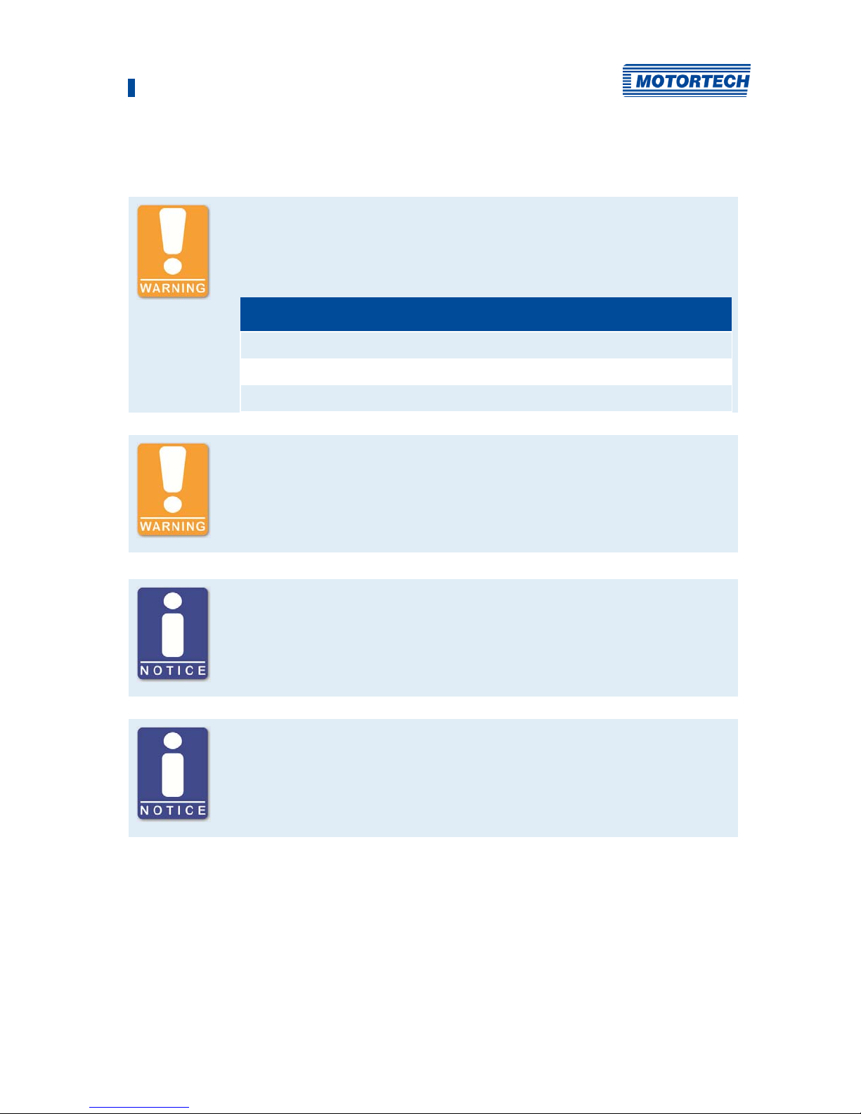
1.3 Which Symbols Are Used in the Operating Manual?
The following symbols are used in this manual and must be observed:
Example
This symbol indicates examples, which point out necessary handling steps
and techniques. In addition, you receive additional information from the
examples, which will increase your knowledge.
Notice
This symbol indicates important notices for the user. Follow these. In
addition, this symbol is used for overviews that give you a summary of the
necessary work steps.
Warning
This symbol indicates warnings for possible risks of property damage or
risks to health. Read these warning notices carefully and take the
mentioned precautionary measures.
1 General Information
1 General Information
Rev. 02/2019 7
Danger
This symbol indicates warnings for danger to life, especially due to high
voltage. Read these warning notices carefully and take the mentioned
precautionary measures.
1.4 Which Abbreviations/Acronyms Are Used in the Operating Manual?
In the manual or the user interface, the following abbreviations / acronyms are used.
Abb. Term Description Explanation
ASO Auxiliary
Synchronization Output
Output of the MOTORTECH
ignition controllers for
synchronization with the
DetCon
CAN
Bus
Controller Area
Network Bus
Bus for control
devices / networks
Asynchronous serial
connection system for
networking control devices
CE Conformité
Européenne
Conformity with EU
directives
Mark based on EU legislation
for certain products in
conjunction with product safety
CSA Canadian Standards
Association
Organization that defines
standards, inspects products
for safety compliance, and
issues pertinent certifications.
DC Direct Current
DetCon
Detonation
Contr
oller
Serves to prevent major engine
damage that can be caused by
knocking combustion.
EMI Electromagnetic
Interference
EMC Electromagnetic
Compatibility
Compatibility of electrical or
electronic equipment items
with their surroundings
HV High Voltage
ISU Ignition Sensor Unit
°KW Crankshaft angle in
degrees
Unit for the rotation angle of
the crankshaft

1 General Information
8 Rev. 02/2019
Abb. Term Description Explanation
LED Light Emitting Diode Light emitting electronic semi-
conductor
MIC MOTORTECH Ignition
Controller
USB Universal Serial Bus Serial wiring system to connect
a computer to external
equipment
9 Rev. 02/2019
2.1 General Safety Instructions
The following safety instructions must be followed in the area in which the device is operated:
High voltage! Danger to life!
While the engine is running, the area around the ignition system especially
holds the risk of danger due to high voltage. The following parts should
therefore not be touched or removed unless explicitly stated otherwise:
– Ignition coils and caps
– Wires of the high voltage circuit
– In- and output wiring of the ignition controller
– Pickups and their wiring
Danger to persons with pacemakers!
Electromagnetic impulses in the wiring of the ignition system may exceed
the permissible limits of pacemakers. Persons with pacemakers must
therefore not be present in the vicinity of the ignition system being
operated. Mark the operating location of the ignition system with the
corresponding standardized warning symbol.
MOTORTECH equipment is manufactured as state of the art and therefore safe and reliable to
operate. Nevertheless the equipment can cause risks or damage can occur, if the following
instructions are not complied with:
– The gas engine must only be operated by trained and authorized personnel.
– Operate the equipment only within the parameters specified in the technical data.
– Use the equipment correctly and for its intended use only.
– Never apply force.
– For all work such as installation, conversion, adaptation, maintenance, and repair, all
equipment must be disconnected from the mains and secured against unintentional
reactivation.
– Perform only such maintenance and repair work as is described in this operating manual,
and follow the instructions given while working.
– Only use spare parts supplied by MOTORTECH for the maintenance of the device.
– Further work must only be performed by personnel authorized by MOTORTECH. Non-
compliance with the instructions will void any warranties for the proper function of the
equipment as well as the responsibility for the validity of the certifications.
– Safety devices must not be dismounted or disabled.
2 Safety Instructions

2 Safety Instructions
10 Rev. 02/2019
– Avoid all activities that can impair the function of the equipment.
– Operate the equipment only while it is in proper condition.
– Investigate all changes detected while operating the gas engine or ignition system.
– Ensure compliance with all laws, directives and regulations applicable to the operation of
your system, including such not expressly stated herein.
– If the system is not entirely tight and sealed, gas may escape and result in explosion hazard.
The inhalation of gas can also lead to death or severe health damages. Therefore, upon
completion of all assembly works, always check the system's tightness.
– Always ensure adequate ventilation of the engine compartment.
– Ensure a safe position at the gas engine.
– There is a risk of burning on hot surfaces. Allow the engine to cool down before starting any
work.
– Personal protective equipment (PPE), e.g. safety shoes and gloves, must be worn during all
work on the engine.
– Your behavior can reduce possible residual risks to a minimum. Pay attention to a
responsible handling of the gas engine and the gas-carrying system.
2.2 Electrostatic Discharge Hazards
Electronic equipment is sensitive to static electricity. To protect these components from damage
caused by static electricity, special precautions must be taken to minimize or prevent
electrostatic discharge.
Observe these safety precautions while you work with the equipment or in its vicinity.
– Before performing maintenance or repair work, ensure that the static electricity inherent to
your body is discharged.
– Do not wear clothing made from synthetic materials to prevent static electricity from
building up. Your clothing should therefore be made of cotton or cotton mix materials.
– Keep plastics such as vinyl and Styrofoam materials as far away from the control system, the
modules, and the work environment as possible.
– Do not remove the circuit boards from the enclosure of the device.
2 Safety Instructions
Rev. 02/2019 11
2.3 Special Safety Instructions for the Device
High voltage! Danger to life!
There is danger to life while the engine is operating due to high voltage. The
following safety instructions must therefore be observed when the engine is
running:
– Do not touch the ignition sensor unit (ISU)
– Do not remove the ignition sensor unit (ISU)
– Do not loosen the wiring
Risk of destruction due to electrostatic discharge!
The DetCon detonation controller may only be installed in a switch cabinet
by qualified personnel trained in the handling of ESD-endangered
components, observing the ESD regulations. The ESD standard IEC 61340-51:2016 must be observed during installation. No warranty is given for
damage due to electrostatic discharge.
Operational safety
The DetCon detonation controller requires high voltage ignition wires
with integrated 5 kΩ resistance, as otherwise interference in the detonation
sensor signals may be caused. Any other ignition wires must be replaced.
Risk of damage
The detonation sensor attachment screws must not be tightened too firmly,
as otherwise the sensors will be damaged and no longer function
properly.Observe the following information for sensor mounting:
– Torque: 20 Nm ± 5 Nm (14.8 ± 3.7 lb-ft) for mounting screws:
– made of cast iron: M8 x 25 mm (0.98"), Strength: 8.8
– made of aluminium: M8 x 30 mm (1.18"), strength: 8.8
– Torque: 15 Nm ± 5 Nm (11 lb-ft ±2.2 lb-ft) for M6 fixing screws, strength
10.9 with sleeve
2 Safety Instructions
12 Rev. 02/2019
Operational safety
Please note that the detonation sensors must be mounted according to the
firing order of the cylinders. Refer to the pertinent section Wiring of the
Detonation Sensors on page 57.
Detonation detection
The DetCon detonation controller detects knocking as far as possible, but
not bindingly.
DetCon only usable in single ignition mode
V-engines can only use the DetCon detonation controller with single
ignition and not in double ignition mode.
The DetCon uses two time windows per cylinder to detect engine knocking.
These time windows are opened in single ignition mode based on the
ignition pulse. In double ignition mode it is not possible to correctly assign
the time windows to all cylinders.
2.4 Proper Disposal
After the expiration of its service life, MOTORTECH equipment can be disposed of with other
commercial waste, or it may be returned to MOTORTECH. We will ensure its environmentally
friendly disposal.
13 Rev. 02/2019
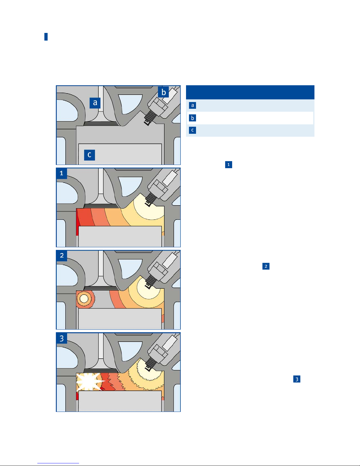
3.1 Functional Description
Pos. Designation
Valve
Spar
k plug
Piston
Normal Comb
ustion
The graphics
show the desired type of
combustion of the gas/air mixture in the
combustion chamber. The ignition spark
ignites the gas/air mixture. The flame front
spreads out evenly in the combustion
chamber with the specific laminar flame
speed of the gas/air mixture. The cylinder
pressure increases slightly during
combustion.
Knocking Combustion
Knocking combustion arises if the gas/air
mixture self-ignites before the actual flame
front, but after the ignition
. This system
does not detect so-called early ignition.
The reason for this is an excessive increase
in pressure and temperature of the as yet
non-combusted mixture due to the pressure
and temperature fronts preceding the normal
flame front. The pressure and temperature
fronts arising from the self-ignition, in turn,
make further self-ignitions possible. Highfrequency pressure waves arise in the
combustion chamber, which are introduced
into the engine structure via the walls of the
combustion chamber and released as airborne noise into the environment. The
knocking becomes audible in this way
.
Compared to normal combustion,
significantly higher peak pressures arise,
which may lead to major engine damage in
addition to the higher thermal load.
3 Intended Use
3 Intended Use
14 Rev. 02/2019
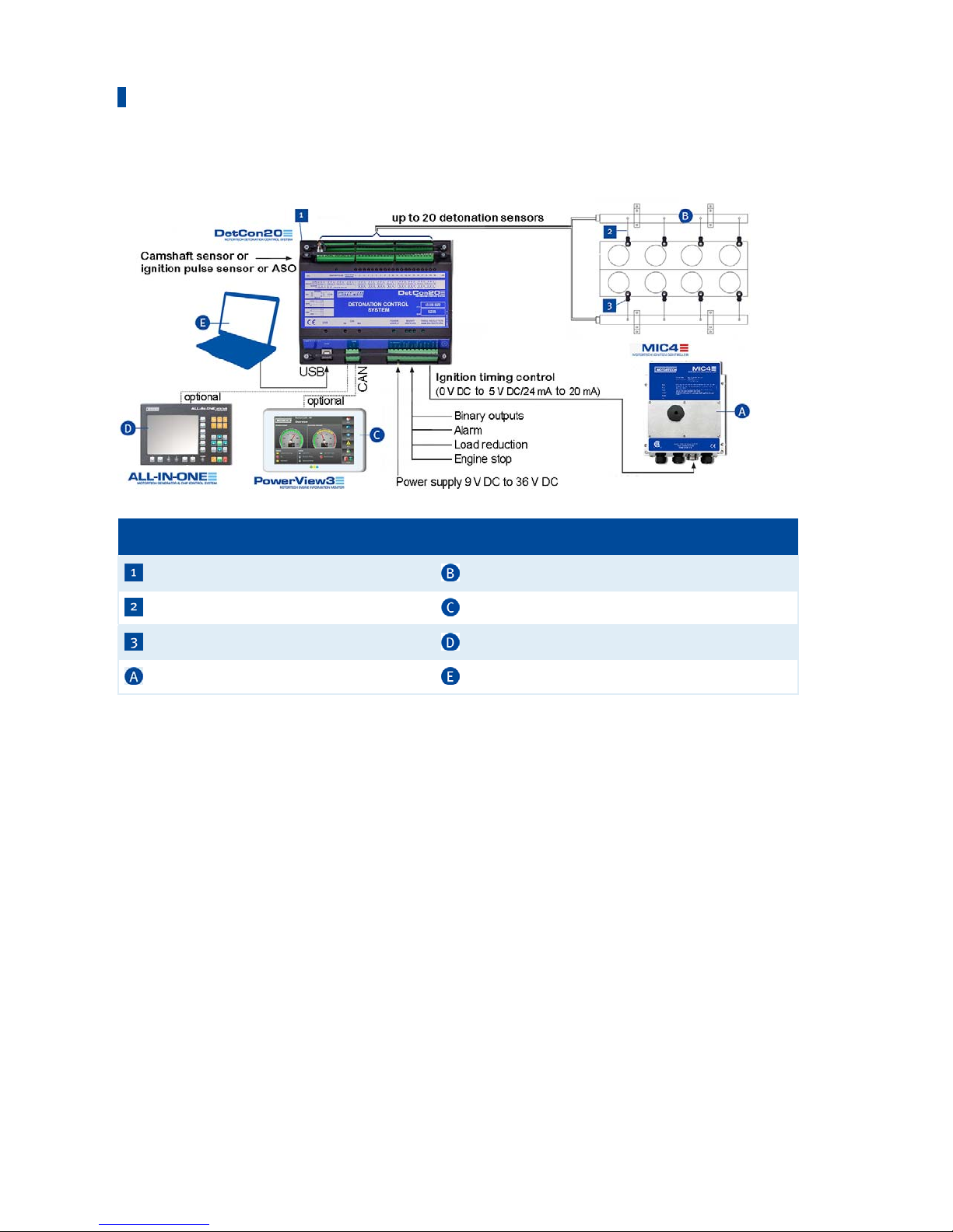
Detonation Control System – Overview
Pos. no Description Pos. no Description
DetCon detonation controller Wiring rail (ignition)
Deto
nation sensor wiring
Po
werView3
Detonation sensor ALL-IN-ONE
Ignitio
n controller
Laptop
Deto
nation Controller
The task of the DetCon detonation controller is to avoid engine damage from knocking
combustion.
Vibration occurs in the engine compartment during the combustion process. These have a
frequency which is characteristic for the engine type. The DetCon measures the vibratory energy
within a narrow frequency range which is typical for the respective engine. The energy measured
is proportional to the knocking level.
Measurement is only carried out within operating cycles in which combustion is possible. This
increases the sensitivity of the measurement and minimizes its reaction to random noises. The
operating cycles are determined according to application and the ignition controller used via an
auxiliary synchronization output, an ignition sensor unit (ISU) or a camshaft sensor.
3 Intended Use
Rev. 02/2019 15
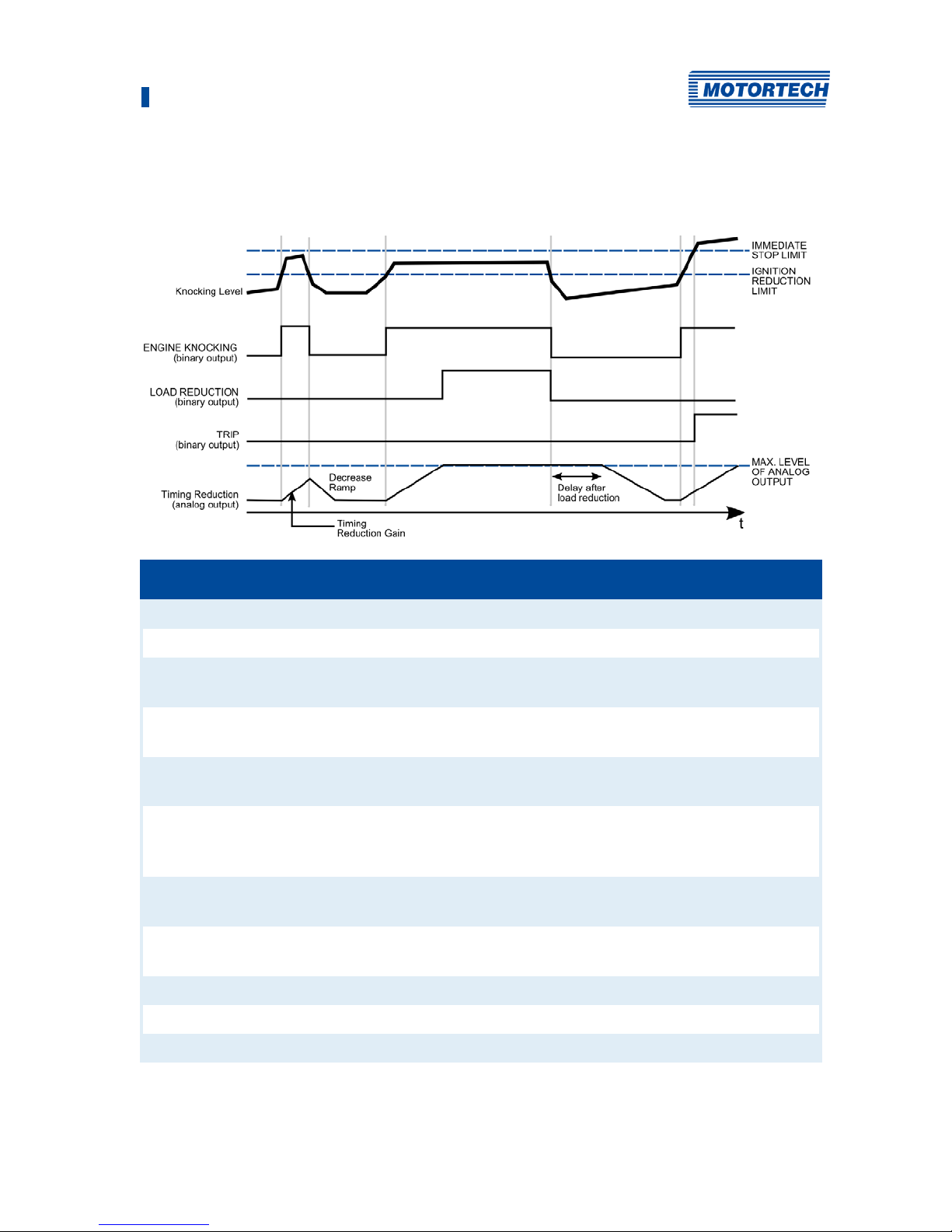
The following diagram and the explanations below it illustrate the basic control process of the
system:
Term used in diagram Description
Knocking Level Example of the progression of knocking energy
IMMEDIATE STOP LIMIT The maximum value at which the engine is stopped
IGNITION REDUCTION LIMIT The maximum value upon which an ignition timing reduction
is performed
ENGINE KNOCKING (binary
output)
Signal on the binary output indicating knocking.
LOAD REDUCTION (binary
output)
Signal on the binary output effecting load reduction.
TRIP (binary output) Signal on the binary output indicating that the IMMEDIATE
STOP LIMIT has been exceeded or that a faulty sensor has
been detected.
Timing Reduction (analog
output)
Curve of the analog signal for timing reduction
MAX. LEVEL OF ANALOG
OUTPUT
Maximum value of the timing reduction
Timing Reduction Gain Speed of the timing reduction
Decrease Ramp Speed of the timing reduction
Delay after load reduction Delay time following a load reduction

3 Intended Use
16 Rev. 02/2019
The measured knocking energy (Knocking Level curve) is compared in every cycle with a preset
maximum value (IGNITION REDUCTION LIMIT). If this maximum value is reached, the binary
output ENGINE KNOCKING is activated. At the same time, the analog outputs change their values
(Timing Reduction curve). The rate at which the value of the signal changes is specified by the
setting Timing Reduction Gain. The analog signals are transmitted to the ignition controller, thus
adjusting the ignition timing. If this causes the knocking energy to fall below the maximum
value, the values at the analog outputs are also reduced. The rate of this reduction is adjusted
according to the preset value Decrease Ramp.
If the ignition timing can no longer be corrected via the analog outputs and the engine is still
knocking, the binary output for load reduction (LOAD REDUCTION) is activated. A master control
(e.g. ALL-IN-ONE) can control load reduction via this output.
LOAD REDUCTION is deactivated again if the engine knocking stops. However, the analog
outputs remain active for a further period which is set via the function Delay after load reduction.
This period must be longer than required for reaching full load.
The third binary output, i.e. TRIP, is activated when the knocking exceeds the maximum value
IMMEDIATE STOP LIMIT. This can be used as an emergency stop signal to force the engine to stop.
Checkbox Enable bad sensor detect
Activate the checkbox so that faulty knock sensors are indicated by the BAD
SENSOR status display. This function only detects sensors that supply
faulty signals. If there is a cable break or a sensor does not supply a signal
at all for any other reason, this is not indicated. If a faulty sensor is
detected, the binary output TRIP is also switched..

3 Intended Use
Rev. 02/2019 17
3.2 Applications
The DetCon detonation controller can analyze two-stroke and four-stroke engines with up to 20
cylinders and up to a maximum 1 kHz ignition frequency. The device is available in two versions:
– DetCon2 for two detonation sensors
– DetCon20 for up to 20 detonation sensors
Both device types are available as a built-in device for a control cabinet or with a CSA certified
enclosure. The following manual applies to both device types. Any differences between the two
versions are clearly identified.
In order to define the time frame for potential knocking, the detonation controller must know the
ignition timing of the first cylinder in the firing sequence. Depending on the application and the
ignition controller used, this can be determined in different ways:
– Gas engines:
– MOTORTECH ignition controllers with auxiliary synchronization output ASO (e. g. MIC6)
The ignition timing is determined via the signal on the ASO output. No other sensor is
required.
– Ignition controllers without ASO output:
The ignition timing is determined using a signal from the ignition sensor unit (ISU)
connected between the ignition output and the ignition coil of the first cylinder
– Diesel and pilot injection engines:
– The fuel injection timing is determined using the signal from an inductive camshaft
sensor.
Any use other than the one described in the operating manual shall be considered improper use
and will result in the voiding of all warranties.
3.3 Application in hazardous areas
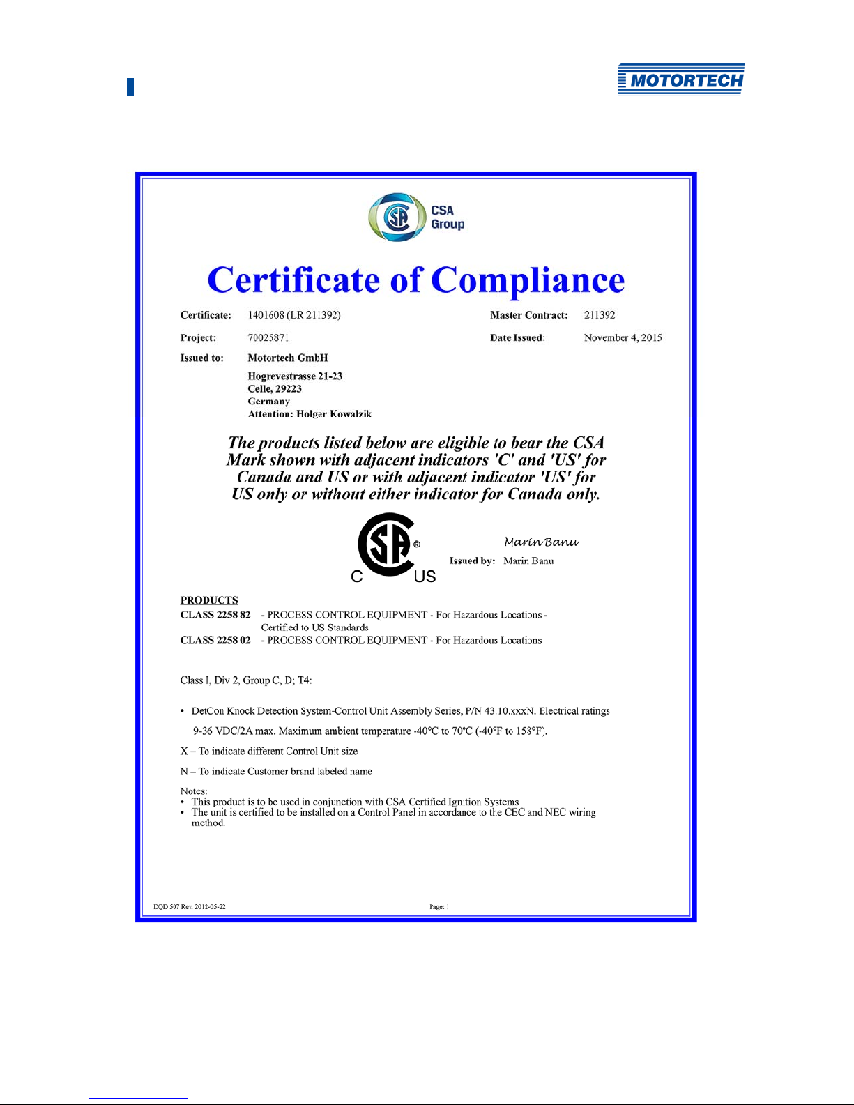
3.3.1 USA, Canada
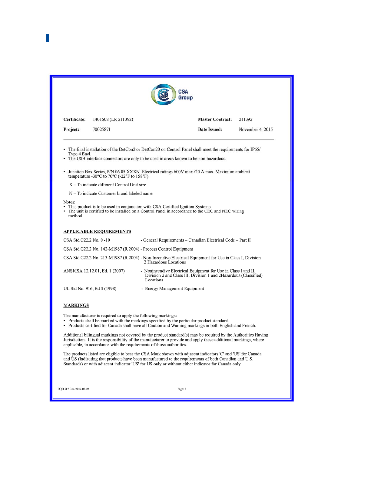
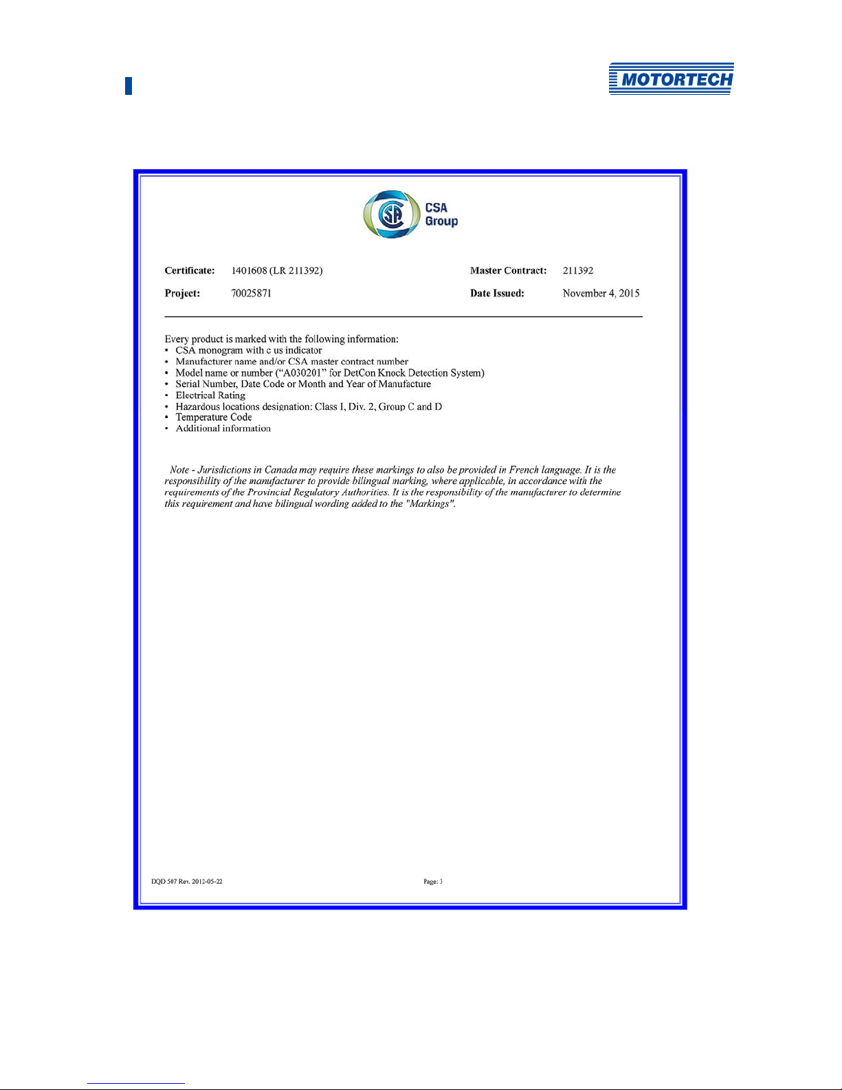
The DetCon detonation controller is certified by the CSA for use in a Class I, Division 2, Groups C
and D, T4 hazardous area in the USA and Canada. It is essential that you observe the
instructions of the CSA certificate 1401608 (LR 211392) (see Certification section).
The DetCon detonation controller can be supplied in a CSA-certified housing (P/N 43.00.102, P/N
43.00.202, P/N 43.00.120, P/N 43.00.220) or installed in an appropriately certified switch
cabinet and thus complies with the guidelines mentioned in the Certification section.
3 Intended Use
18 Rev. 02/2019
3.3.2 European Union
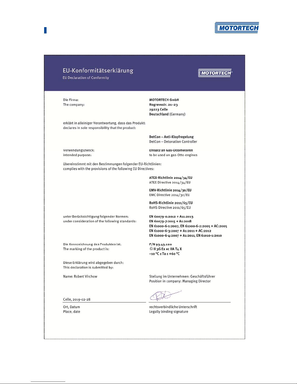
The DetCon detonation controller in ATEX enclosure is certified according to ATEX directive
2014/34/EU for use in a potentially explosive atmosphere in the European Union:
II 3G Ex ec IIA T4
Labeling Description
Symbol for explosion protection, the product complies with ATEX
directive 2014/34/EU
II Device group
II = Ex-areas with the exception of mines at risk of firedamp
3G Equipment category
3 = Ex-hazard rare and short-term
Substance group
G = Gases
Ex Explosion protection according to EN 60079-xx, (-0, -7 )
ec Type of ignition protection
ec = Device protection through increased safety "e"
IIA Subdivision into explosion groups:
II = Gases
A = Gases such as propane
T4 Temperature class
T4 = max. surface temperature ≤ +135 °C (+275 °F)
X X = Special conditions must be observed when using the operating
resources
3 Intended Use
Rev. 02/2019 19
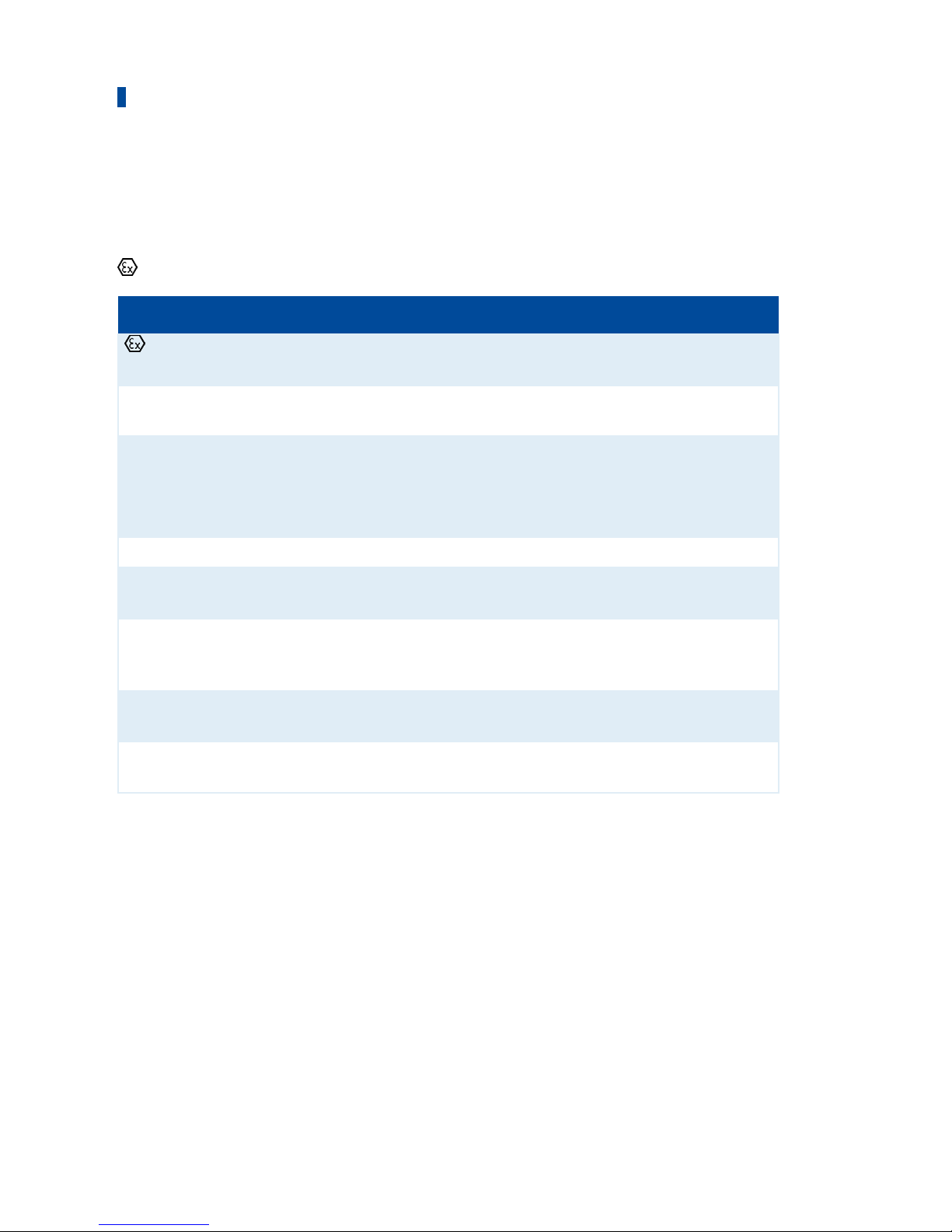
Instructions for handling the DetCon20 detonation controller in hazardous areas
Danger of explosion!
Only use the detonation sensor approved by MOTORTECH and the required
number of blocking capacitor boards for operation in hazardous areas.
P/N Description
43.20.001 Detonation sensor without sensor lead, two-pole
43.30.004-60 Detonation sensor lead, 18 m (59.06 ft)
43.20.029 Blocking capacitor board (ATEX)
Danger of explosion!
The USB interface may only be used in a non-hazardous atmosphere. There
is a danger of sparking.
Sealing of the enclosure to the enclosure cover
The enclosure is sealed against the enclosure cover by a foamed silicone
seal. The overlapping of the foam bead (start point/end point) of the seal
cannot be produced without any joints due to the material, but has no
influence on the specified IP protection class.
Use MOTORTECH detonation sensors
DetCon detonation controller systems are parameterized for operation with
MOTORTECH detonation sensors (piezoelectric acceleration transducers).
The use of other sensors entails a new calibration of the engine.

20 Rev. 02/2019
4.1 Technical Data
4.1.1 Certifications
The detonation controller of the DetCon series are certified as per the following regulations:
CSA
The DetCon detonation controllers can be supplied in a CSA certified enclosure.
The applied requirements are:
– Class I, Div. 2, Group C,D; T4
– CSA Std. C22.2 No. 0-10
– CSA Std. C22.2 No. 142-M1987 (R 2004)
– CSA Std. C22.2 No. 213-M1987 (R 2004)
– ANSI/ISA 12.12.01, Ed. 1 (2007)
– UL Std. No. 916, Ed. 3 (1998)
The corresponding directives are also met if the DetCon detonation controller is installed in a
correspondingly certified switch cabinet.
P/N Device Description
43.00.002 DetCon2 Detonation
Controlle
Two inputs, CSA, IP20, for mounting in a CSAcertified control cabinet
43.00.102 DetCon2 Detonation
Controller
Two inputs, IP 20, built into a CSA-certified
enclosure, including ISU ignition sensor unit P/N
43.20.002
43.00.202 DetCon2 Detonation
Controller
Two inputs, IP 20, built into a CSA-certified
enclosure
43.00.020 DetCon20 Detonation
Controller
20 inputs, CSA, IP20, for mounting in a CSA-certified
control cabinet
43.00.120 DetCon20 Detonation
Controller
20 inputs, IP 20, built into a CSA-certified enclosure,
including ISU Ignition sensor unit P/N 43.20.002
43.00.220 DetCon20 Detonation
Controller
20 inputs, IP 20, built into a CSA-certified enclosure
4 Product Description

4 Product Description
Rev. 02/2019 21
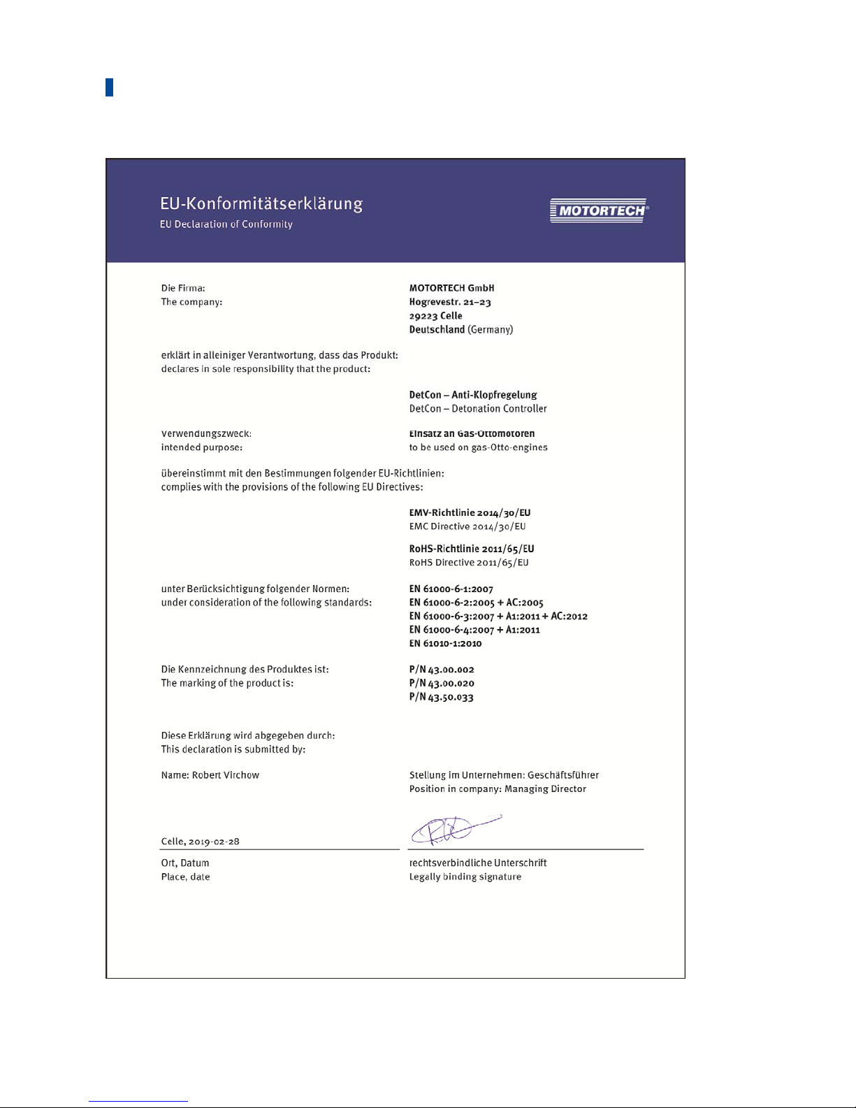
CE
The DetCon detonation controllers P/N 43.00.002, P/N 43.00.020 and P/N 43.50.033 comply
with the following EU directives:
– EMC Directive 2014/30/EU
– EN 61000-6-1:2007
Electromagnetic compatibility (EMC) - Part 6-1: Generic standards –
Immunity to interference for residential, commercial and light-industrial environments
– EN 61000-6-2:2005 + AC:2005
Electromagnetic compatibility (EMC) – Part 6-2: Generic standards –
Immunity for industrial environments
– EN 61000-6-3:2007 + A1:2011 + AC:2012
Electromagnetic compatibility (EMC) – Part 6-3: Generic standards –
Emission for residential, commercial and light-industrial environments
– EN 61000-6-4:2007 + A1:2011
Electromagnetic compatibility (EMC) – Part 6-4: Generic standards –
Emission for industrial environments
– RoHS Directive 2011/65/EU
– Other standards applied:
– EN 61010-1:2010
Safety requirements for electrical equipment for measurement, control, and laboratory
use –
Part 1: General requirements
P/N Device Description
43.00.002 DetCon2 Detonation
Controller
Two inputs, CSA, IP20, in use without control
cabinet only in non-hazardous areas
43.00.020 DetCon20 Detonation
Controller
20 inputs, CSA, IP20, in use without control
cabinet only in non-hazardous areas
43.50.003 DetCon20 Detonation
Controller
20 inputs, IP20, exclusively for use in nonhazardous areas

4 Product Description
22 Rev. 02/2019
The DetCon detonation controller can be supplied in an ATEX-certified enclosure (P/N 93.43.220)
and additionally complies with the following directive:
– ATEX Directive 2014/34/EU
– EN 60079-0:2012 + A11:2013
Potentially explosive atmospheres – Part 0: Equipment – General requirements
– EN 60079-7:2015 + A1:2018
Potentially explosive atmospheres – Part 7: Equipment protection by increased safety "e
P/N Device Description
93.43.220 DetCon20 Detonation
Controller
20 inputs, IP 20, built into an ATEX-certified
enclosure
4 Product Description
Rev. 02/2019 23
4 Product Description
24 Rev. 02/2019
4 Product Description
Rev. 02/2019 25
4 Product Description
26 Rev. 02/2019
4 Product Description
Rev. 02/2019 27
 Loading...