

Page 1
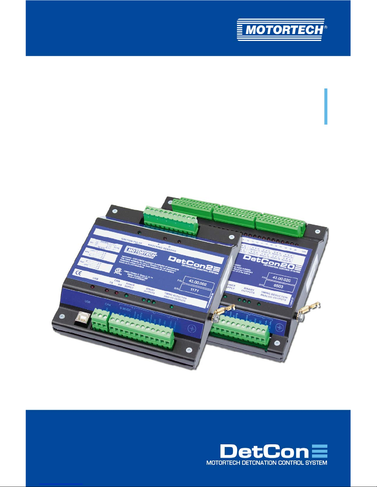
DetCon –Detonation Controller
Operating Manual
P/N 01.30.002 | Rev. 02/2019
Page 2

Original instructions
Copyright
© Copyright 2019 MOTORTECH GmbH. All rights reserved.
Distribution and reproduction of this publication or parts thereof, regardless of the specific
purpose and form, are not permissible without express written approval by MOTORTECH.
Information contained in this publication may be changed without prior notice.
Trademarks
MOTORTECH products and the MOTORTECH logo are registered and/or common law trademarks
of the MOTORTECH GmbH. All further trademarks and logos displayed or used in this publication
are the property of the respective entitled person.
Page 3

Rev. 02/2019 3
1 General Information .................................................................................................... 6
1.1 What Is the Purpose of this Operating Manual? ......................................................... 6
1.2 Who Is this Operating Manual Targeted to? ............................................................... 6
1.3 Which Symbols Are Used in the Operating Manual? ................................................... 6
1.4 Which Abbreviations/Acronyms Are Used in the Operating Manual? ........................... 7
2 Safety Instructions ..................................................................................................... 9
2.1 General Safety Instructions ..................................................................................... 9
2.2 Electrostatic Discharge Hazards ............................................................................ 10
2.3 Special Safety Instructions for the Device ............................................................... 11
2.4 Proper Disposal .................................................................................................... 12
3 Intended Use ............................................................................................................. 13
3.1 Functional Description .......................................................................................... 13
3.2 Applications ......................................................................................................... 17
3.3 Application in hazardous areas ............................................................................. 17
3.3.1 USA, Canada ...................................................................................................... 17
3.3.2 European Union ................................................................................................. 18
4 Product Description ...................................................................................................20
4.1 Technical Data ...................................................................................................... 20
4.1.1 Certifications ..................................................................................................... 20
4.1.2 Mechanical Data ................................................................................................ 28
4.1.3 Warning Notices on the Device ............................................................................ 29
4.1.4 Product Identification - Labels on the Device ........................................................ 30
4.1.5 Electrical Data .................................................................................................... 31
4.1.6 Interfaces .......................................................................................................... 32
4.1.7 Technical Data of the Detonation Sensors ............................................................ 32
4.1.8 Technical Data of the Ignition Sensor Unit (ISU) ................................................... 34
4.1.9 Technical Data of the Camshaft Sensor ................................................................ 34
4.1.10 Requirements for External Equipment ................................................................ 35
4.1.11 Overview Drawings ........................................................................................... 35
5 Installation Instructions ............................................................................................. 41
5.1 Ground Connection / Protective Conductor Connection on ATEX Enclosure ................ 43
5.2 Lead bushings through the enclosure wall on the ATEX enclosure ............................ 45
5.3 Mounting the Detonation Sensors .......................................................................... 49
5.4 Mounting the Ignition Sensor Unit (ISU) ................................................................. 54
5.5 Mounting the Camshaft Sensor .............................................................................. 56
Table of Contents
Page 4

Table of Contents
4 Rev. 02/2019
6 Wiring of the Device ................................................................................................... 57
6.1 Wiring of the Detonation Sensors .......................................................................... 57
6.2 Wiring for Ignition Controller with ASO Output ....................................................... 58
6.3 Wiring of the Ignition Sensor Unit (ISU) .................................................................. 60
6.4 Wiring of the Camshaft Sensor (for Diesel and Pilot Injection Engines Only) ............. 62
6.5 Wiring of the Binary Outputs ................................................................................. 64
6.6 Wiring of the Analog Outputs for Ignition Timing Reduction ..................................... 65
6.7 Wiring CAN Bus .................................................................................................... 66
7 Functions ................................................................................................................... 67
7.1 Ignition Timing Reduction ...................................................................................... 67
7.2 Load Reduction .................................................................................................... 67
7.3 Engine Stop ......................................................................................................... 67
8 DenEdit Settings ....................................................................................................... 68
8.1 DenEdit System Requirements ............................................................................... 68
8.2 Installation and First Steps in DenEdit ................................................................... 69
8.3 User Interface Overview ........................................................................................ 72
8.4 Menu Bar and Toolbar .......................................................................................... 73
8.5 Display Area of the Analog Output Signal and the Knocking Intensity ....................... 74
8.6 Error and Status Displays ..................................................................................... 74
8.7 Tabs for Process Monitoring .................................................................................. 76
8.7.1 Tab: Actual Knocking Values ............................................................................... 76
8.7.2 Tab: Knocking History ........................................................................................ 77
8.8 Tabs for the Process Parameters ........................................................................... 77
8.8.1 Tab: Mode ......................................................................................................... 78
8.8.2 Tab: Knocking Params ....................................................................................... 79
8.8.3 Tab: Input Gains ................................................................................................ 80
8.8.4 Tab: Firing Sequence ......................................................................................... 80
8.8.5 Tab: Output Options .......................................................................................... 81
8.8.6 Tab: CAN Params ............................................................................................... 82
8.9 Status Bar ........................................................................................................... 83
9 Operation ................................................................................................................. 84
9.1 Start-up ............................................................................................................... 84
9.2 Shutdown ............................................................................................................ 84
Page 5

Table of Contents
Rev. 02/2019 5
10 Disturbances ............................................................................................................ 85
11 Maintenance ............................................................................................................ 86
11.1 Spare Parts and Accessories ................................................................................. 86
12 Index ....................................................................................................................... 87
Page 6
6 Rev. 02/2019
Read through this operating manual carefully before use and become familiar with the product.
Installation and start-up should not be carried out before reading and understanding this
document. Keep this manual readily available so that you can reference it as needed.
1.1 What Is the Purpose of this Operating Manual?
This manual serves as an aid for the installation and operation of the product and supports the
technical staff with all operating and maintenance tasks to be performed. Furthermore, this
manual is aimed at preventing dangers to life and health of the user and third parties.
1.2 Who Is this Operating Manual Targeted to?
The operating manual provides a code of conduct for personnel tasked with the setup,
operation, maintenance, and repair of gas engines. A certain level of technical knowledge with
respect to the operation of gas engines and basic knowledge of electronic ignition systems are
necessary. Persons who are only authorized to operate the gas engine shall be trained by the
operating company and shall be expressly instructed concerning potential hazards.
1.3 Which Symbols Are Used in the Operating Manual?
The following symbols are used in this manual and must be observed:
Example
This symbol indicates examples, which point out necessary handling steps
and techniques. In addition, you receive additional information from the
examples, which will increase your knowledge.
Notice
This symbol indicates important notices for the user. Follow these. In
addition, this symbol is used for overviews that give you a summary of the
necessary work steps.
Warning
This symbol indicates warnings for possible risks of property damage or
risks to health. Read these warning notices carefully and take the
mentioned precautionary measures.
1 General Information
Page 7
1 General Information
Rev. 02/2019 7
Danger
This symbol indicates warnings for danger to life, especially due to high
voltage. Read these warning notices carefully and take the mentioned
precautionary measures.
1.4 Which Abbreviations/Acronyms Are Used in the Operating Manual?
In the manual or the user interface, the following abbreviations / acronyms are used.
Abb. Term Description Explanation
ASO Auxiliary
Synchronization Output
Output of the MOTORTECH
ignition controllers for
synchronization with the
DetCon
CAN
Bus
Controller Area
Network Bus
Bus for control
devices / networks
Asynchronous serial
connection system for
networking control devices
CE Conformité
Européenne
Conformity with EU
directives
Mark based on EU legislation
for certain products in
conjunction with product safety
CSA Canadian Standards
Association
Organization that defines
standards, inspects products
for safety compliance, and
issues pertinent certifications.
DC Direct Current
DetCon
Detonation
Contr
oller
Serves to prevent major engine
damage that can be caused by
knocking combustion.
EMI Electromagnetic
Interference
EMC Electromagnetic
Compatibility
Compatibility of electrical or
electronic equipment items
with their surroundings
HV High Voltage
ISU Ignition Sensor Unit
°KW Crankshaft angle in
degrees
Unit for the rotation angle of
the crankshaft
Page 8

1 General Information
8 Rev. 02/2019
Abb. Term Description Explanation
LED Light Emitting Diode Light emitting electronic semi-
conductor
MIC MOTORTECH Ignition
Controller
USB Universal Serial Bus Serial wiring system to connect
a computer to external
equipment
Page 9
9 Rev. 02/2019
2.1 General Safety Instructions
The following safety instructions must be followed in the area in which the device is operated:
High voltage! Danger to life!
While the engine is running, the area around the ignition system especially
holds the risk of danger due to high voltage. The following parts should
therefore not be touched or removed unless explicitly stated otherwise:
– Ignition coils and caps
– Wires of the high voltage circuit
– In- and output wiring of the ignition controller
– Pickups and their wiring
Danger to persons with pacemakers!
Electromagnetic impulses in the wiring of the ignition system may exceed
the permissible limits of pacemakers. Persons with pacemakers must
therefore not be present in the vicinity of the ignition system being
operated. Mark the operating location of the ignition system with the
corresponding standardized warning symbol.
MOTORTECH equipment is manufactured as state of the art and therefore safe and reliable to
operate. Nevertheless the equipment can cause risks or damage can occur, if the following
instructions are not complied with:
– The gas engine must only be operated by trained and authorized personnel.
– Operate the equipment only within the parameters specified in the technical data.
– Use the equipment correctly and for its intended use only.
– Never apply force.
– For all work such as installation, conversion, adaptation, maintenance, and repair, all
equipment must be disconnected from the mains and secured against unintentional
reactivation.
– Perform only such maintenance and repair work as is described in this operating manual,
and follow the instructions given while working.
– Only use spare parts supplied by MOTORTECH for the maintenance of the device.
– Further work must only be performed by personnel authorized by MOTORTECH. Non-
compliance with the instructions will void any warranties for the proper function of the
equipment as well as the responsibility for the validity of the certifications.
– Safety devices must not be dismounted or disabled.
2 Safety Instructions
Page 10

2 Safety Instructions
10 Rev. 02/2019
– Avoid all activities that can impair the function of the equipment.
– Operate the equipment only while it is in proper condition.
– Investigate all changes detected while operating the gas engine or ignition system.
– Ensure compliance with all laws, directives and regulations applicable to the operation of
your system, including such not expressly stated herein.
– If the system is not entirely tight and sealed, gas may escape and result in explosion hazard.
The inhalation of gas can also lead to death or severe health damages. Therefore, upon
completion of all assembly works, always check the system's tightness.
– Always ensure adequate ventilation of the engine compartment.
– Ensure a safe position at the gas engine.
– There is a risk of burning on hot surfaces. Allow the engine to cool down before starting any
work.
– Personal protective equipment (PPE), e.g. safety shoes and gloves, must be worn during all
work on the engine.
– Your behavior can reduce possible residual risks to a minimum. Pay attention to a
responsible handling of the gas engine and the gas-carrying system.
2.2 Electrostatic Discharge Hazards
Electronic equipment is sensitive to static electricity. To protect these components from damage
caused by static electricity, special precautions must be taken to minimize or prevent
electrostatic discharge.
Observe these safety precautions while you work with the equipment or in its vicinity.
– Before performing maintenance or repair work, ensure that the static electricity inherent to
your body is discharged.
– Do not wear clothing made from synthetic materials to prevent static electricity from
building up. Your clothing should therefore be made of cotton or cotton mix materials.
– Keep plastics such as vinyl and Styrofoam materials as far away from the control system, the
modules, and the work environment as possible.
– Do not remove the circuit boards from the enclosure of the device.
Page 11
2 Safety Instructions
Rev. 02/2019 11
2.3 Special Safety Instructions for the Device
High voltage! Danger to life!
There is danger to life while the engine is operating due to high voltage. The
following safety instructions must therefore be observed when the engine is
running:
– Do not touch the ignition sensor unit (ISU)
– Do not remove the ignition sensor unit (ISU)
– Do not loosen the wiring
Risk of destruction due to electrostatic discharge!
The DetCon detonation controller may only be installed in a switch cabinet
by qualified personnel trained in the handling of ESD-endangered
components, observing the ESD regulations. The ESD standard IEC 61340-51:2016 must be observed during installation. No warranty is given for
damage due to electrostatic discharge.
Operational safety
The DetCon detonation controller requires high voltage ignition wires
with integrated 5 kΩ resistance, as otherwise interference in the detonation
sensor signals may be caused. Any other ignition wires must be replaced.
Risk of damage
The detonation sensor attachment screws must not be tightened too firmly,
as otherwise the sensors will be damaged and no longer function
properly.Observe the following information for sensor mounting:
– Torque: 20 Nm ± 5 Nm (14.8 ± 3.7 lb-ft) for mounting screws:
– made of cast iron: M8 x 25 mm (0.98"), Strength: 8.8
– made of aluminium: M8 x 30 mm (1.18"), strength: 8.8
– Torque: 15 Nm ± 5 Nm (11 lb-ft ±2.2 lb-ft) for M6 fixing screws, strength
10.9 with sleeve
Page 12
2 Safety Instructions
12 Rev. 02/2019
Operational safety
Please note that the detonation sensors must be mounted according to the
firing order of the cylinders. Refer to the pertinent section Wiring of the
Detonation Sensors on page 57.
Detonation detection
The DetCon detonation controller detects knocking as far as possible, but
not bindingly.
DetCon only usable in single ignition mode
V-engines can only use the DetCon detonation controller with single
ignition and not in double ignition mode.
The DetCon uses two time windows per cylinder to detect engine knocking.
These time windows are opened in single ignition mode based on the
ignition pulse. In double ignition mode it is not possible to correctly assign
the time windows to all cylinders.
2.4 Proper Disposal
After the expiration of its service life, MOTORTECH equipment can be disposed of with other
commercial waste, or it may be returned to MOTORTECH. We will ensure its environmentally
friendly disposal.
Page 13
13 Rev. 02/2019
3.1 Functional Description
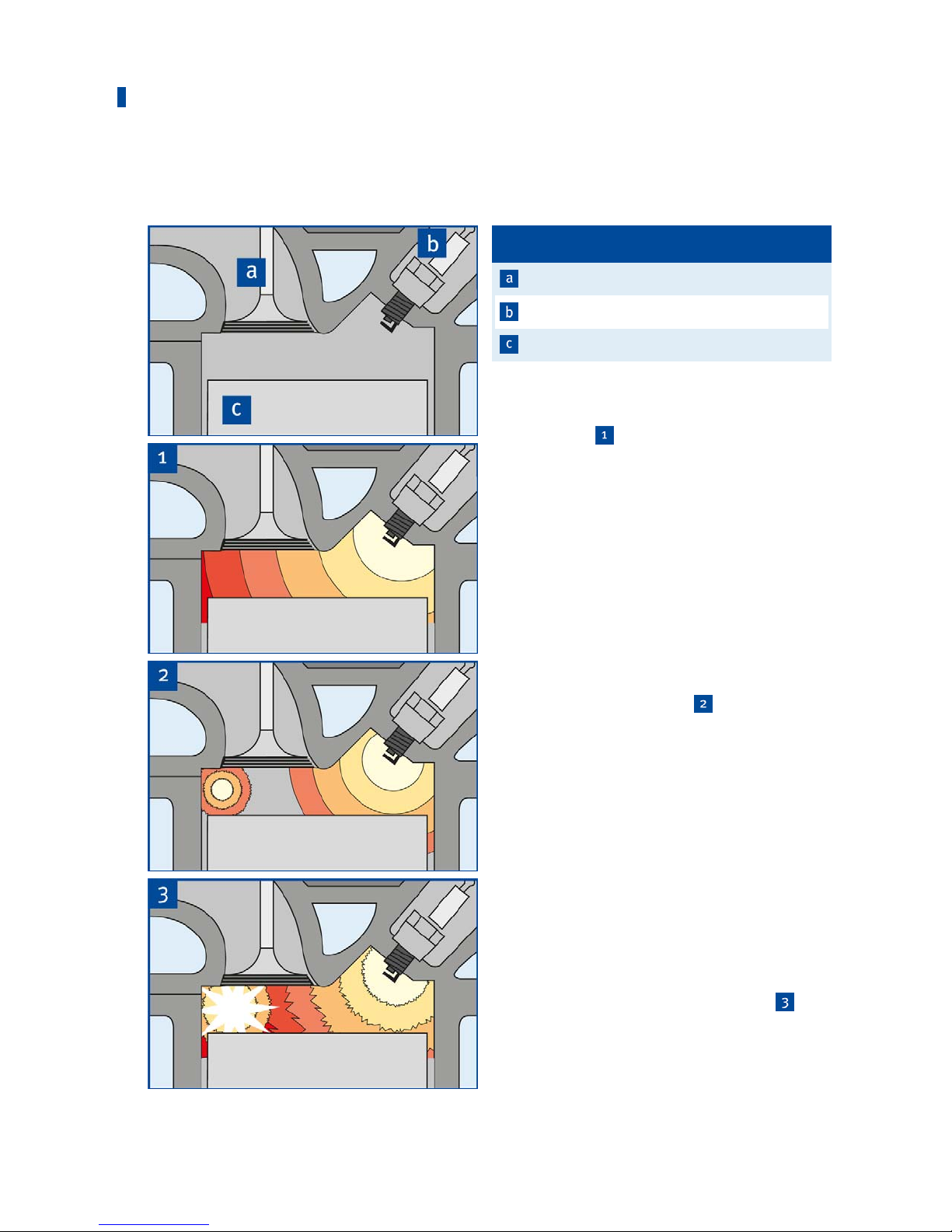
Pos. Designation
Valve
Spar
k plug
Piston
Normal Comb
ustion
The graphics
show the desired type of
combustion of the gas/air mixture in the
combustion chamber. The ignition spark
ignites the gas/air mixture. The flame front
spreads out evenly in the combustion
chamber with the specific laminar flame
speed of the gas/air mixture. The cylinder
pressure increases slightly during
combustion.
Knocking Combustion
Knocking combustion arises if the gas/air
mixture self-ignites before the actual flame
front, but after the ignition
. This system
does not detect so-called early ignition.
The reason for this is an excessive increase
in pressure and temperature of the as yet
non-combusted mixture due to the pressure
and temperature fronts preceding the normal
flame front. The pressure and temperature
fronts arising from the self-ignition, in turn,
make further self-ignitions possible. Highfrequency pressure waves arise in the
combustion chamber, which are introduced
into the engine structure via the walls of the
combustion chamber and released as airborne noise into the environment. The
knocking becomes audible in this way
.
Compared to normal combustion,
significantly higher peak pressures arise,
which may lead to major engine damage in
addition to the higher thermal load.
3 Intended Use
Page 14
3 Intended Use
14 Rev. 02/2019
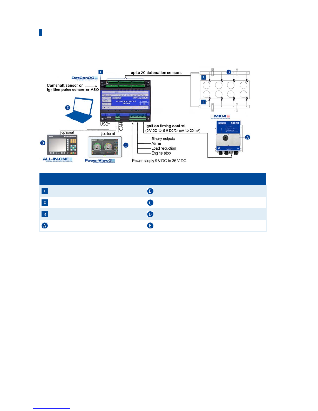
Detonation Control System – Overview
Pos. no Description Pos. no Description
DetCon detonation controller Wiring rail (ignition)
Deto
nation sensor wiring
Po
werView3
Detonation sensor ALL-IN-ONE
Ignitio
n controller
Laptop
Deto
nation Controller
The task of the DetCon detonation controller is to avoid engine damage from knocking
combustion.
Vibration occurs in the engine compartment during the combustion process. These have a
frequency which is characteristic for the engine type. The DetCon measures the vibratory energy
within a narrow frequency range which is typical for the respective engine. The energy measured
is proportional to the knocking level.
Measurement is only carried out within operating cycles in which combustion is possible. This
increases the sensitivity of the measurement and minimizes its reaction to random noises. The
operating cycles are determined according to application and the ignition controller used via an
auxiliary synchronization output, an ignition sensor unit (ISU) or a camshaft sensor.
Page 15
3 Intended Use
Rev. 02/2019 15
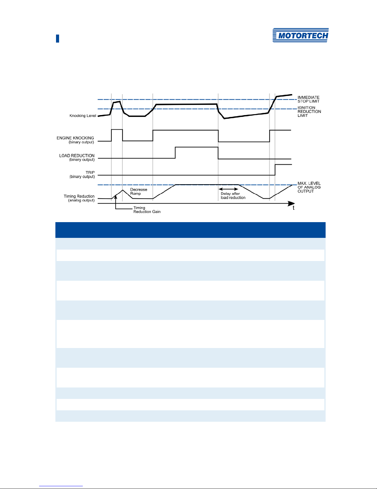
The following diagram and the explanations below it illustrate the basic control process of the
system:
Term used in diagram Description
Knocking Level Example of the progression of knocking energy
IMMEDIATE STOP LIMIT The maximum value at which the engine is stopped
IGNITION REDUCTION LIMIT The maximum value upon which an ignition timing reduction
is performed
ENGINE KNOCKING (binary
output)
Signal on the binary output indicating knocking.
LOAD REDUCTION (binary
output)
Signal on the binary output effecting load reduction.
TRIP (binary output) Signal on the binary output indicating that the IMMEDIATE
STOP LIMIT has been exceeded or that a faulty sensor has
been detected.
Timing Reduction (analog
output)
Curve of the analog signal for timing reduction
MAX. LEVEL OF ANALOG
OUTPUT
Maximum value of the timing reduction
Timing Reduction Gain Speed of the timing reduction
Decrease Ramp Speed of the timing reduction
Delay after load reduction Delay time following a load reduction
Page 16

3 Intended Use
16 Rev. 02/2019
The measured knocking energy (Knocking Level curve) is compared in every cycle with a preset
maximum value (IGNITION REDUCTION LIMIT). If this maximum value is reached, the binary
output ENGINE KNOCKING is activated. At the same time, the analog outputs change their values
(Timing Reduction curve). The rate at which the value of the signal changes is specified by the
setting Timing Reduction Gain. The analog signals are transmitted to the ignition controller, thus
adjusting the ignition timing. If this causes the knocking energy to fall below the maximum
value, the values at the analog outputs are also reduced. The rate of this reduction is adjusted
according to the preset value Decrease Ramp.
If the ignition timing can no longer be corrected via the analog outputs and the engine is still
knocking, the binary output for load reduction (LOAD REDUCTION) is activated. A master control
(e.g. ALL-IN-ONE) can control load reduction via this output.
LOAD REDUCTION is deactivated again if the engine knocking stops. However, the analog
outputs remain active for a further period which is set via the function Delay after load reduction.
This period must be longer than required for reaching full load.
The third binary output, i.e. TRIP, is activated when the knocking exceeds the maximum value
IMMEDIATE STOP LIMIT. This can be used as an emergency stop signal to force the engine to stop.
Checkbox Enable bad sensor detect
Activate the checkbox so that faulty knock sensors are indicated by the BAD
SENSOR status display. This function only detects sensors that supply
faulty signals. If there is a cable break or a sensor does not supply a signal
at all for any other reason, this is not indicated. If a faulty sensor is
detected, the binary output TRIP is also switched..
Page 17

3 Intended Use
Rev. 02/2019 17
3.2 Applications
The DetCon detonation controller can analyze two-stroke and four-stroke engines with up to 20
cylinders and up to a maximum 1 kHz ignition frequency. The device is available in two versions:
– DetCon2 for two detonation sensors
– DetCon20 for up to 20 detonation sensors
Both device types are available as a built-in device for a control cabinet or with a CSA certified
enclosure. The following manual applies to both device types. Any differences between the two
versions are clearly identified.
In order to define the time frame for potential knocking, the detonation controller must know the
ignition timing of the first cylinder in the firing sequence. Depending on the application and the
ignition controller used, this can be determined in different ways:
– Gas engines:
– MOTORTECH ignition controllers with auxiliary synchronization output ASO (e. g. MIC6)
The ignition timing is determined via the signal on the ASO output. No other sensor is
required.
– Ignition controllers without ASO output:
The ignition timing is determined using a signal from the ignition sensor unit (ISU)
connected between the ignition output and the ignition coil of the first cylinder
– Diesel and pilot injection engines:
– The fuel injection timing is determined using the signal from an inductive camshaft
sensor.
Any use other than the one described in the operating manual shall be considered improper use
and will result in the voiding of all warranties.
3.3 Application in hazardous areas
3.3.1 USA, Canada
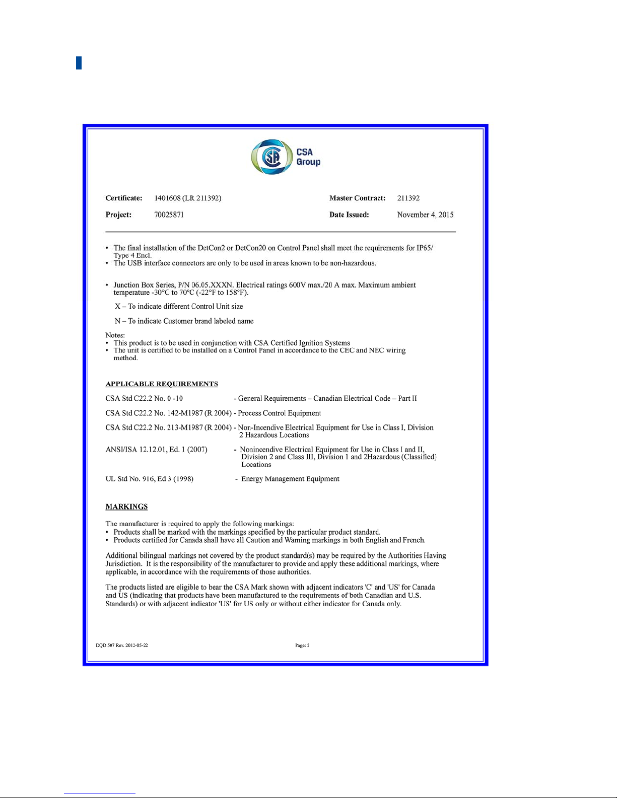
The DetCon detonation controller is certified by the CSA for use in a Class I, Division 2, Groups C
and D, T4 hazardous area in the USA and Canada. It is essential that you observe the
instructions of the CSA certificate 1401608 (LR 211392) (see Certification section).
The DetCon detonation controller can be supplied in a CSA-certified housing (P/N 43.00.102, P/N
43.00.202, P/N 43.00.120, P/N 43.00.220) or installed in an appropriately certified switch
cabinet and thus complies with the guidelines mentioned in the Certification section.
Page 18
3 Intended Use
18 Rev. 02/2019
3.3.2 European Union
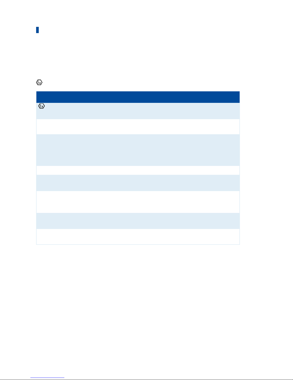
The DetCon detonation controller in ATEX enclosure is certified according to ATEX directive
2014/34/EU for use in a potentially explosive atmosphere in the European Union:
II 3G Ex ec IIA T4
Labeling Description
Symbol for explosion protection, the product complies with ATEX
directive 2014/34/EU
II Device group
II = Ex-areas with the exception of mines at risk of firedamp
3G Equipment category
3 = Ex-hazard rare and short-term
Substance group
G = Gases
Ex Explosion protection according to EN 60079-xx, (-0, -7 )
ec Type of ignition protection
ec = Device protection through increased safety "e"
IIA Subdivision into explosion groups:
II = Gases
A = Gases such as propane
T4 Temperature class
T4 = max. surface temperature ≤ +135 °C (+275 °F)
X X = Special conditions must be observed when using the operating
resources
Page 19
3 Intended Use
Rev. 02/2019 19
Instructions for handling the DetCon20 detonation controller in hazardous areas
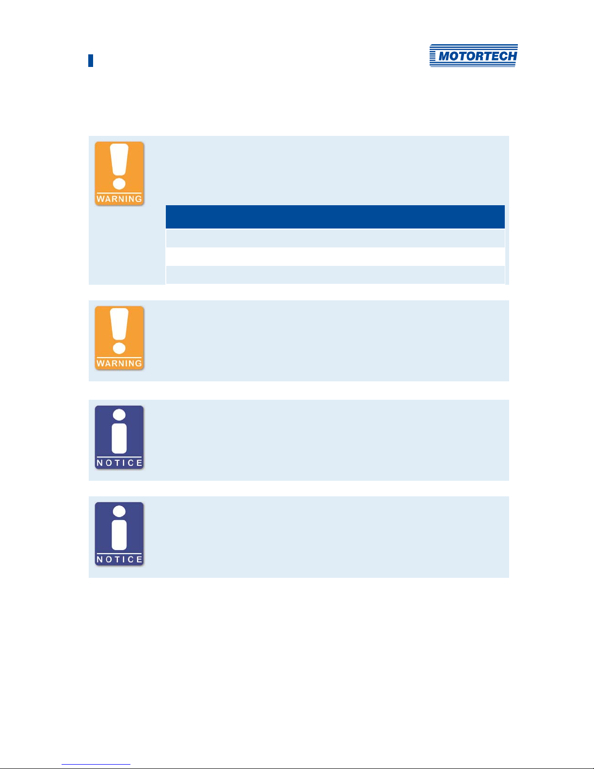
Danger of explosion!
Only use the detonation sensor approved by MOTORTECH and the required
number of blocking capacitor boards for operation in hazardous areas.
P/N Description
43.20.001 Detonation sensor without sensor lead, two-pole
43.30.004-60 Detonation sensor lead, 18 m (59.06 ft)
43.20.029 Blocking capacitor board (ATEX)
Danger of explosion!
The USB interface may only be used in a non-hazardous atmosphere. There
is a danger of sparking.
Sealing of the enclosure to the enclosure cover
The enclosure is sealed against the enclosure cover by a foamed silicone
seal. The overlapping of the foam bead (start point/end point) of the seal
cannot be produced without any joints due to the material, but has no
influence on the specified IP protection class.
Use MOTORTECH detonation sensors
DetCon detonation controller systems are parameterized for operation with
MOTORTECH detonation sensors (piezoelectric acceleration transducers).
The use of other sensors entails a new calibration of the engine.
Page 20

20 Rev. 02/2019
4.1 Technical Data
4.1.1 Certifications
The detonation controller of the DetCon series are certified as per the following regulations:
CSA
The DetCon detonation controllers can be supplied in a CSA certified enclosure.
The applied requirements are:
– Class I, Div. 2, Group C,D; T4
– CSA Std. C22.2 No. 0-10
– CSA Std. C22.2 No. 142-M1987 (R 2004)
– CSA Std. C22.2 No. 213-M1987 (R 2004)
– ANSI/ISA 12.12.01, Ed. 1 (2007)
– UL Std. No. 916, Ed. 3 (1998)
The corresponding directives are also met if the DetCon detonation controller is installed in a
correspondingly certified switch cabinet.
P/N Device Description
43.00.002 DetCon2 Detonation
Controlle
Two inputs, CSA, IP20, for mounting in a CSAcertified control cabinet
43.00.102 DetCon2 Detonation
Controller
Two inputs, IP 20, built into a CSA-certified
enclosure, including ISU ignition sensor unit P/N
43.20.002
43.00.202 DetCon2 Detonation
Controller
Two inputs, IP 20, built into a CSA-certified
enclosure
43.00.020 DetCon20 Detonation
Controller
20 inputs, CSA, IP20, for mounting in a CSA-certified
control cabinet
43.00.120 DetCon20 Detonation
Controller
20 inputs, IP 20, built into a CSA-certified enclosure,
including ISU Ignition sensor unit P/N 43.20.002
43.00.220 DetCon20 Detonation
Controller
20 inputs, IP 20, built into a CSA-certified enclosure
4 Product Description
Page 21

4 Product Description
Rev. 02/2019 21
CE
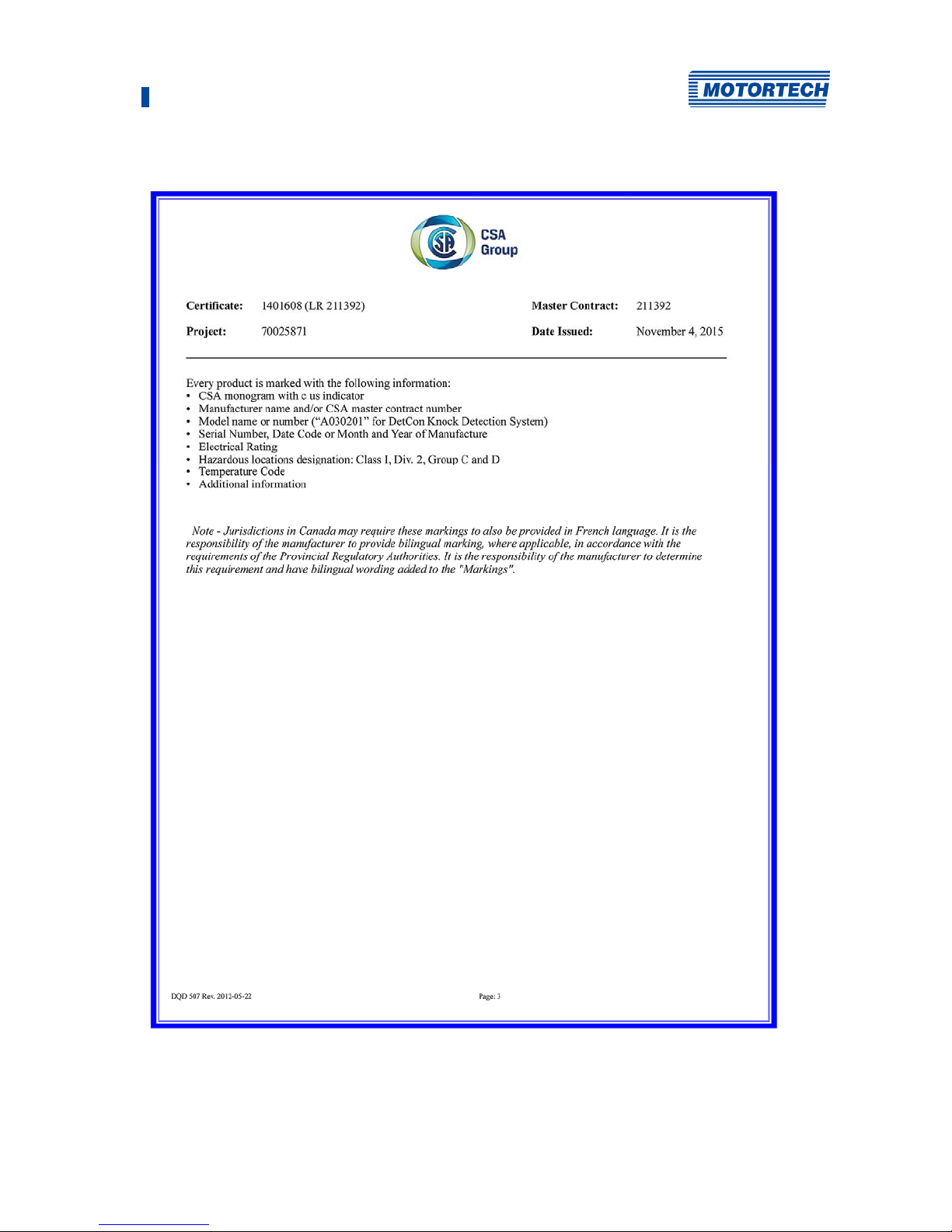
The DetCon detonation controllers P/N 43.00.002, P/N 43.00.020 and P/N 43.50.033 comply
with the following EU directives:
– EMC Directive 2014/30/EU
– EN 61000-6-1:2007
Electromagnetic compatibility (EMC) - Part 6-1: Generic standards –
Immunity to interference for residential, commercial and light-industrial environments
– EN 61000-6-2:2005 + AC:2005
Electromagnetic compatibility (EMC) – Part 6-2: Generic standards –
Immunity for industrial environments
– EN 61000-6-3:2007 + A1:2011 + AC:2012
Electromagnetic compatibility (EMC) – Part 6-3: Generic standards –
Emission for residential, commercial and light-industrial environments
– EN 61000-6-4:2007 + A1:2011
Electromagnetic compatibility (EMC) – Part 6-4: Generic standards –
Emission for industrial environments
– RoHS Directive 2011/65/EU
– Other standards applied:
– EN 61010-1:2010
Safety requirements for electrical equipment for measurement, control, and laboratory
use –
Part 1: General requirements
P/N Device Description
43.00.002 DetCon2 Detonation
Controller
Two inputs, CSA, IP20, in use without control
cabinet only in non-hazardous areas
43.00.020 DetCon20 Detonation
Controller
20 inputs, CSA, IP20, in use without control
cabinet only in non-hazardous areas
43.50.003 DetCon20 Detonation
Controller
20 inputs, IP20, exclusively for use in nonhazardous areas
Page 22

4 Product Description
22 Rev. 02/2019
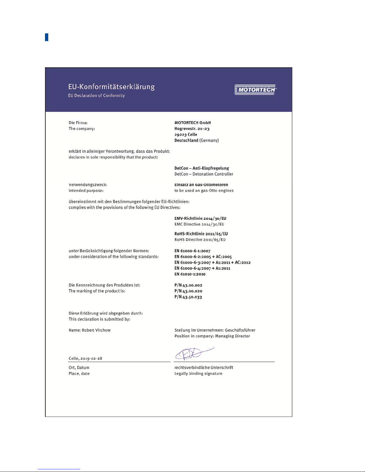
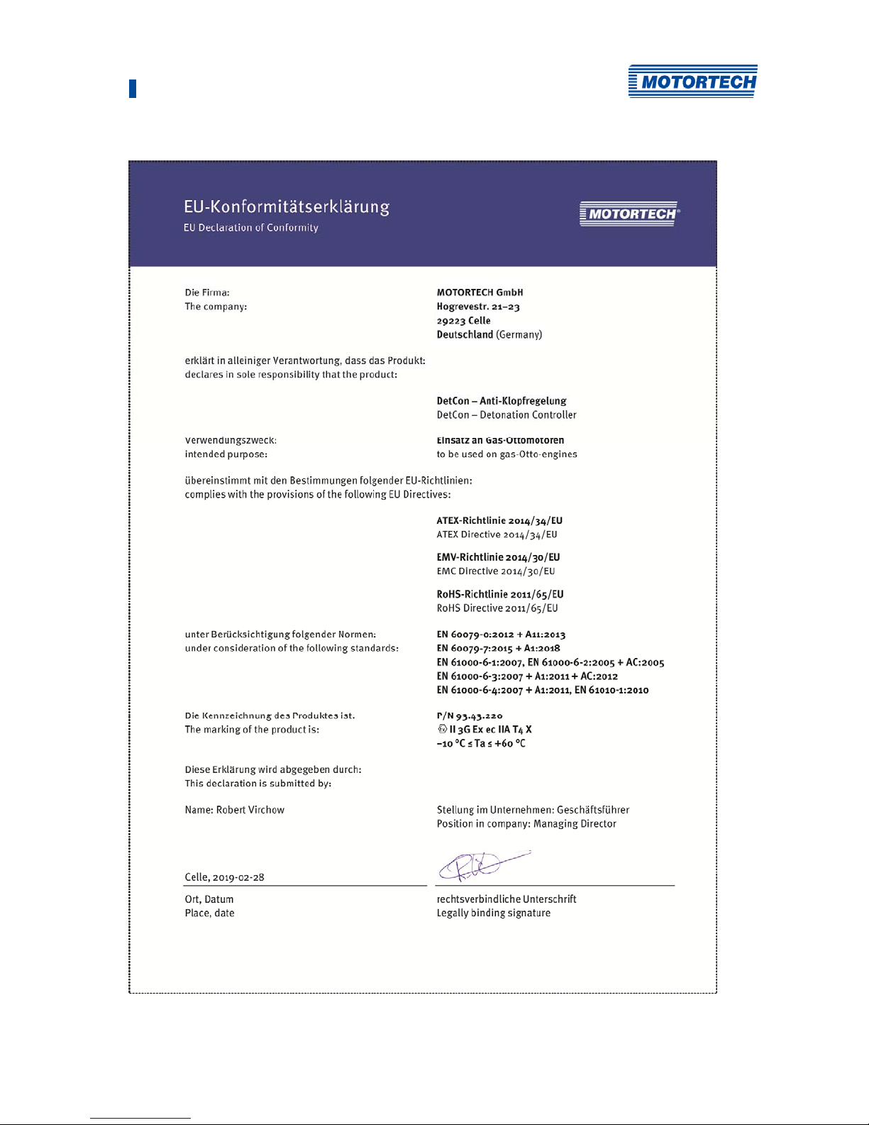
The DetCon detonation controller can be supplied in an ATEX-certified enclosure (P/N 93.43.220)
and additionally complies with the following directive:
– ATEX Directive 2014/34/EU
– EN 60079-0:2012 + A11:2013
Potentially explosive atmospheres – Part 0: Equipment – General requirements
– EN 60079-7:2015 + A1:2018
Potentially explosive atmospheres – Part 7: Equipment protection by increased safety "e
P/N Device Description
93.43.220 DetCon20 Detonation
Controller
20 inputs, IP 20, built into an ATEX-certified
enclosure
Page 23

4 Product Description
Rev. 02/2019 23
Page 24
4 Product Description
24 Rev. 02/2019
Page 25
4 Product Description
Rev. 02/2019 25
Page 26
4 Product Description
26 Rev. 02/2019
Page 27
4 Product Description
Rev. 02/2019 27
Page 28

4 Product Description
28 Rev. 02/2019
4.1.2 Mechanical Data
The DetCon has the following mechanical characteristics:
Feature Value
Dimensions of the electric unit
(incl. DIN rail clamps)
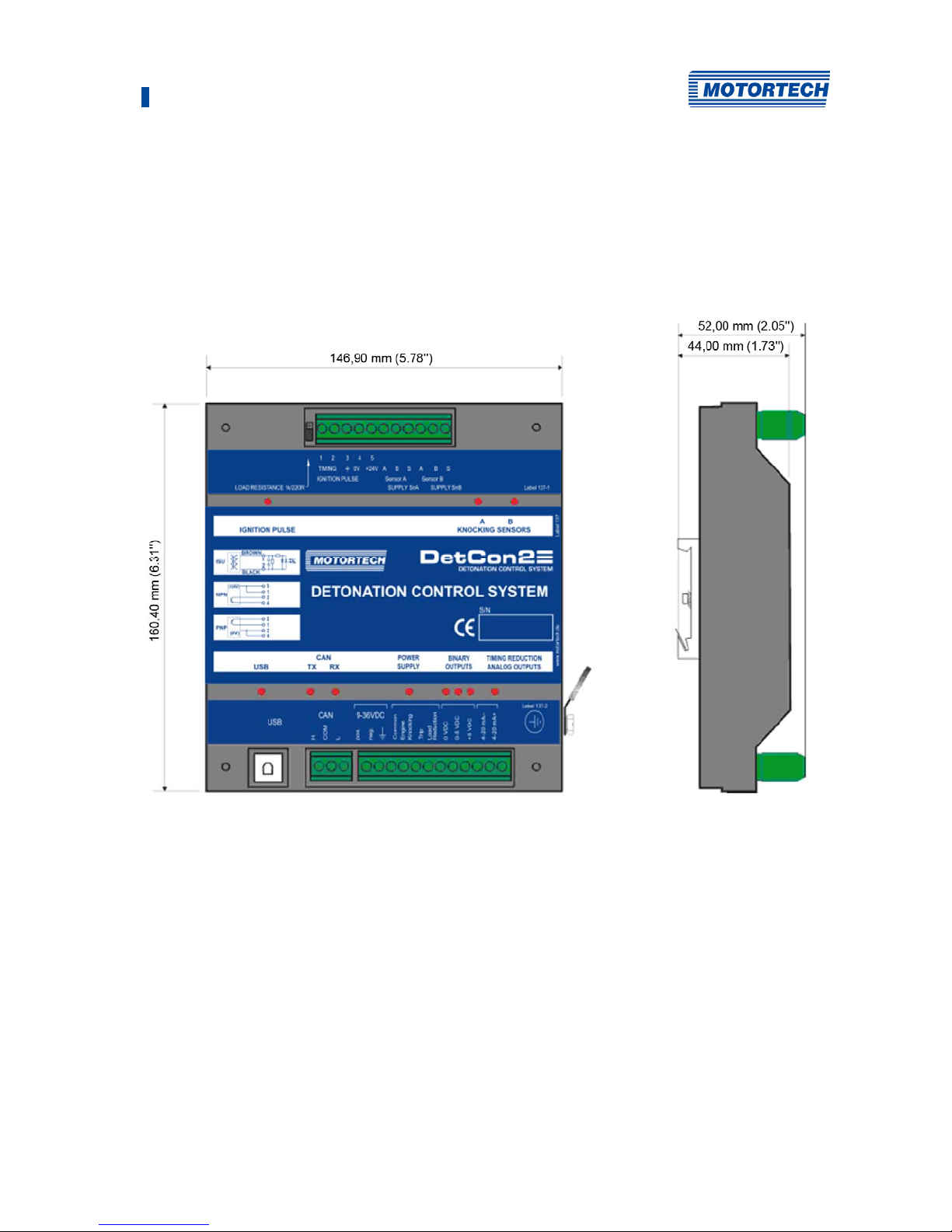
DetCon2
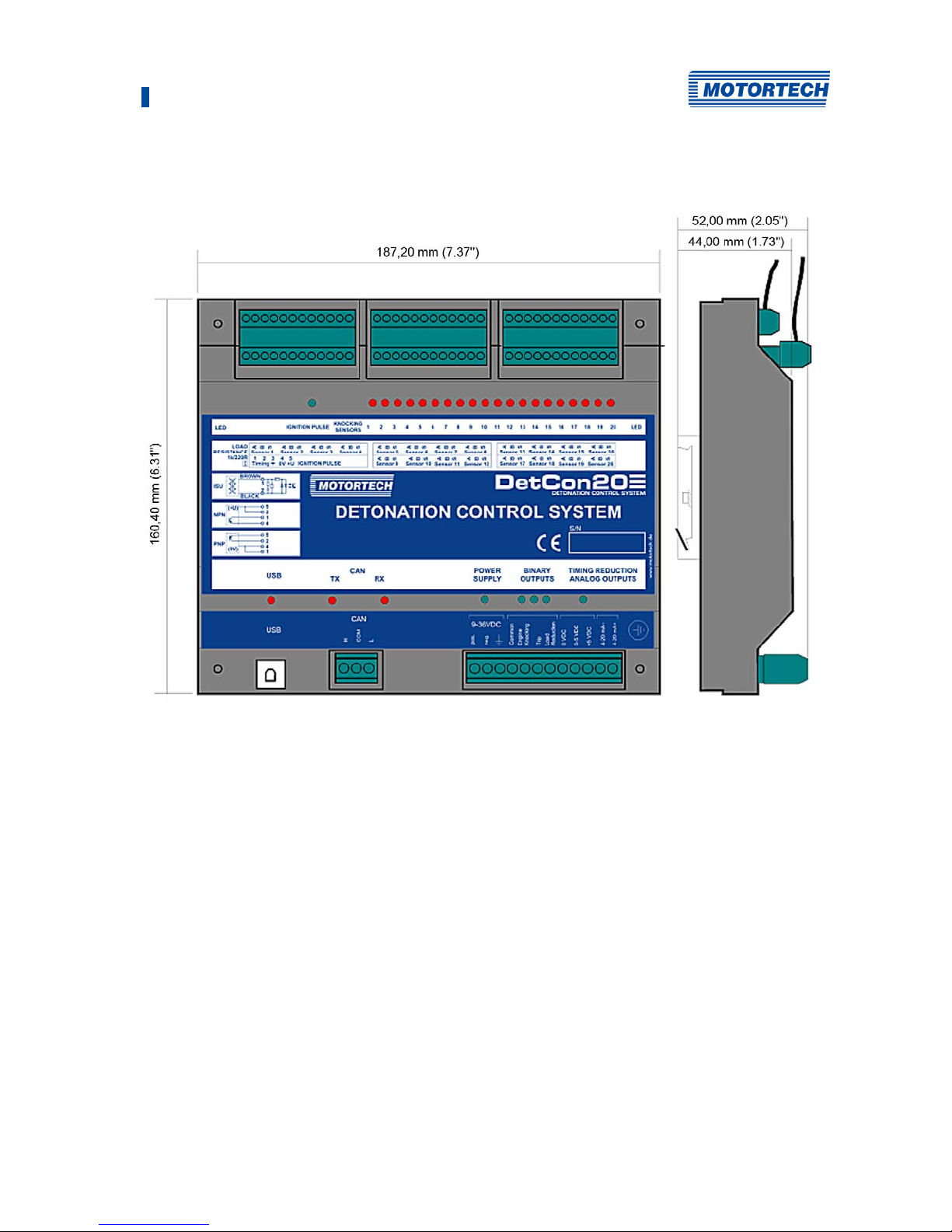
160 mm x 147 mm x 52 mm (6.3" x 7.36" x 2.05")
(length x width x height)
DetCon20
160 mm x 187 mm x 52 mm (6.3" x 5.78" x 2.05")
(length x width x height)
Device in certified enclosure (CSA, ATEX)
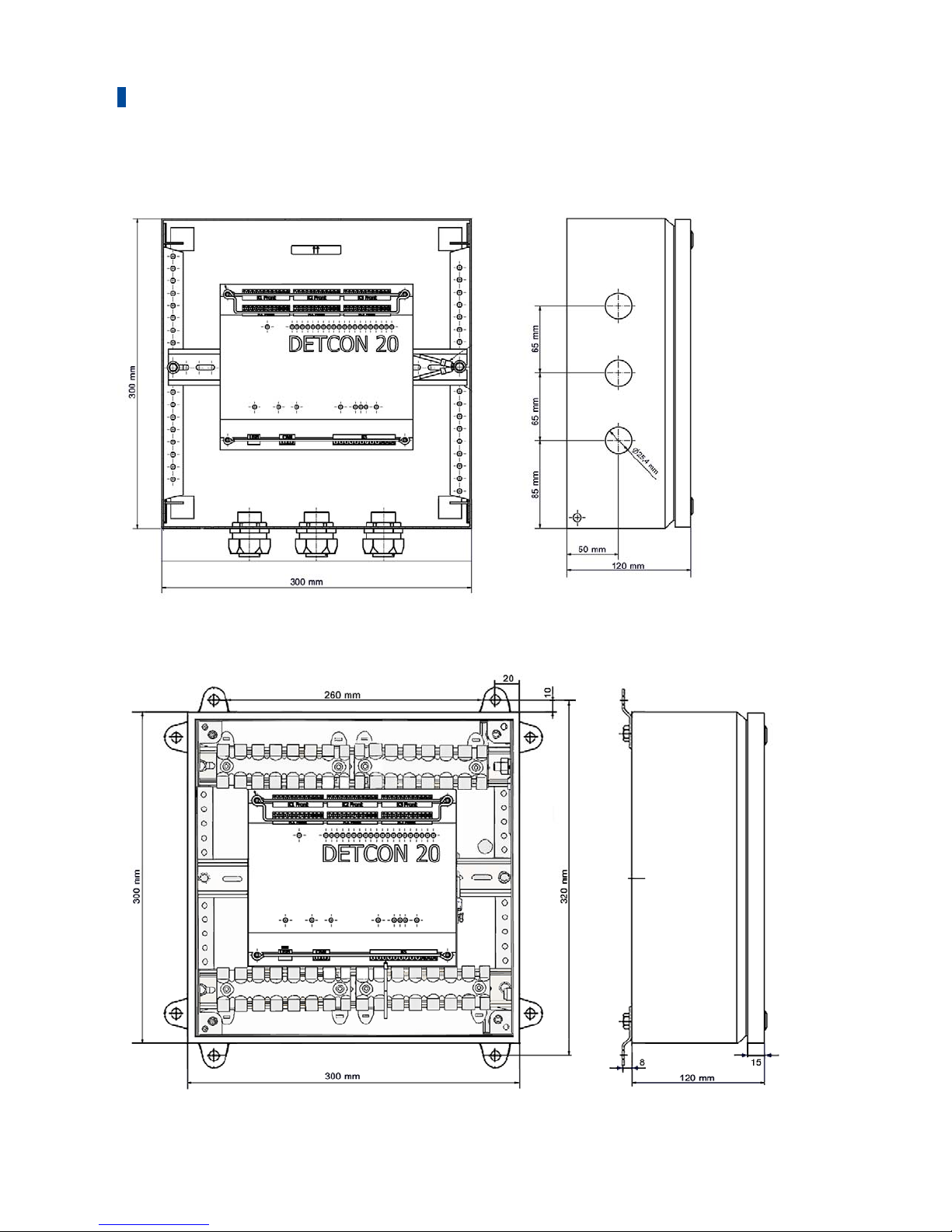
300 mm x 300 mm x 300 mm x 120 mm (11.81" x 11.81" x
4.92")
(length x width x height)
For details, see chapter Overview Drawings on page 35
Mounting for the electric unit DIN rail mounting
Weight DetCon2: 0.59 kg (1.30 lbs)
DetCon20: 0.74 kg (1.63 lbs)
Shape of device See chapter Overview Drawings on page 35
Mechanical Environmental
Conditions
Protection: IP 20
Protection class in potentially hazardous areas ( enclosure
variants): IP 66
Climatic Environmental
Conditions
DetCon without enclosure
Ambient temperature: –10 °C to +60 °C (+14 °F to +140 °F)
Storage temperature; –40 °C to +80 °C (–40 °F to +176 °F)
Device in certified enclosure (CSA, ATEX)
Ambient temperature: –10 °C to +60 °C (+14 °F to +140 °F)
Storage temperature (CSA): –20 °C to +80 °C (–4 °F to +176
°F)
Storage temperature (ATEX): –30 °C to +80 °C (–22 °F to
+176 °F)
max. 95% humidity without condensation
Page 29

4 Product Description
Rev. 02/2019 29
4.1.3 Warning Notices on the Device
The safety instructions on the device or on the enclosure are valid for the DetCon and all
connected components.
Variant Information text
A
TEX and CSA WARNING – EXPLOSION HAZARD – Substitution of components may
impair suitability for Class I, Division 2. Do not disconnect equipment
unless power has been switched off or the area is known to be nonhazardous.
A
ll WARNING! Read and understand the installation and operation manuals
prior to installing or making any adjustments.
ATEX
EXPLOSION HAZARD – Do not open enclosure or disconnect while circuit
is live unless area is known to be non-hazardous. For wiring details
please refer to operation manual.
ATEX
The device must be installed and operated only in an environment that
ensures a pollution degree 2 (or better) according to IEC/EN 60664-1.
A
ll CAUTION – Do not pressure wash this ignition module. Damage to
electronic components may result.
CSA EXPLOSION HAZARD – Do not disconnect while circuit is live unless area
is known to be non-hazardous. For wiring details please refer to
operation manual
Page 30
4 Product Description
30 Rev. 02/2019
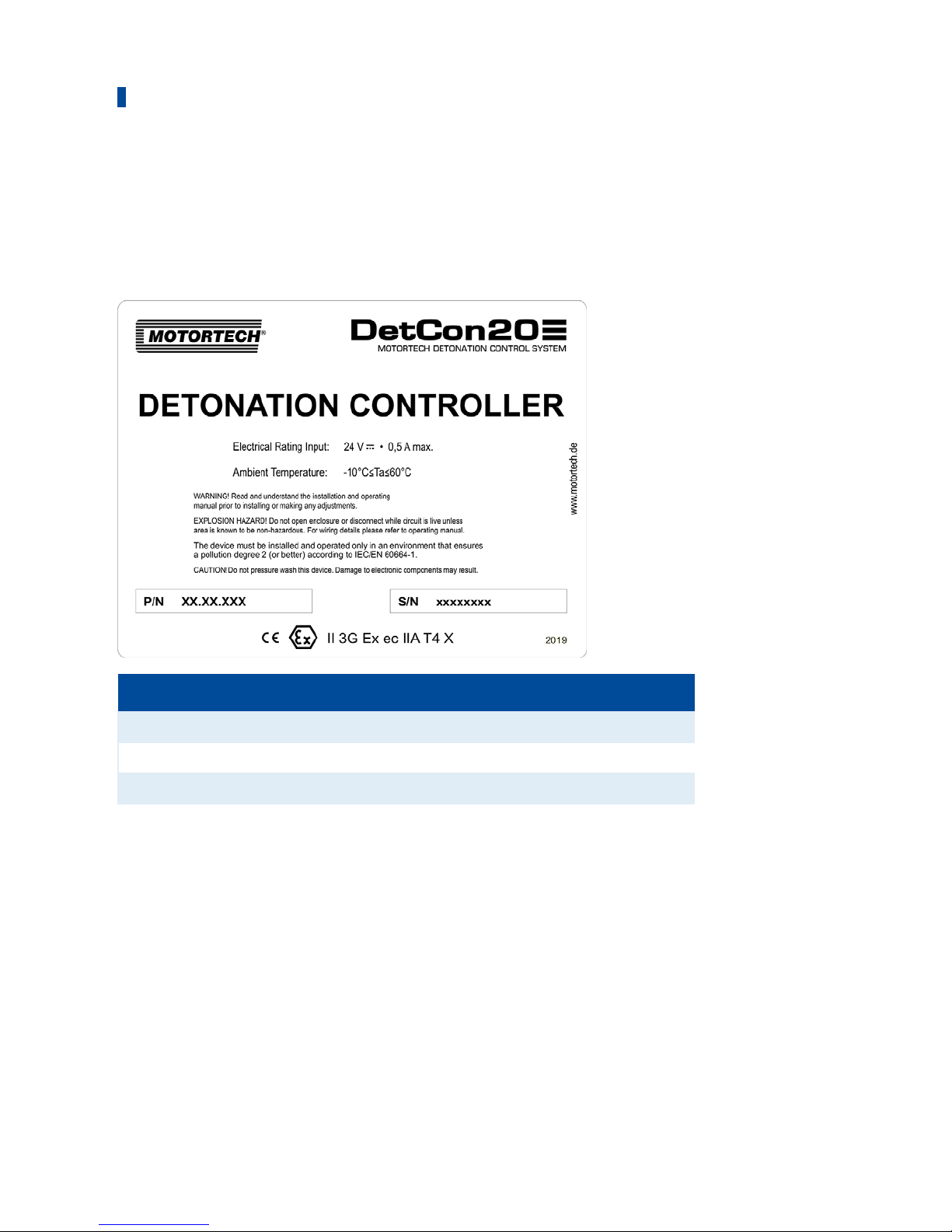
4.1.4 Product Identification - Labels on the Device
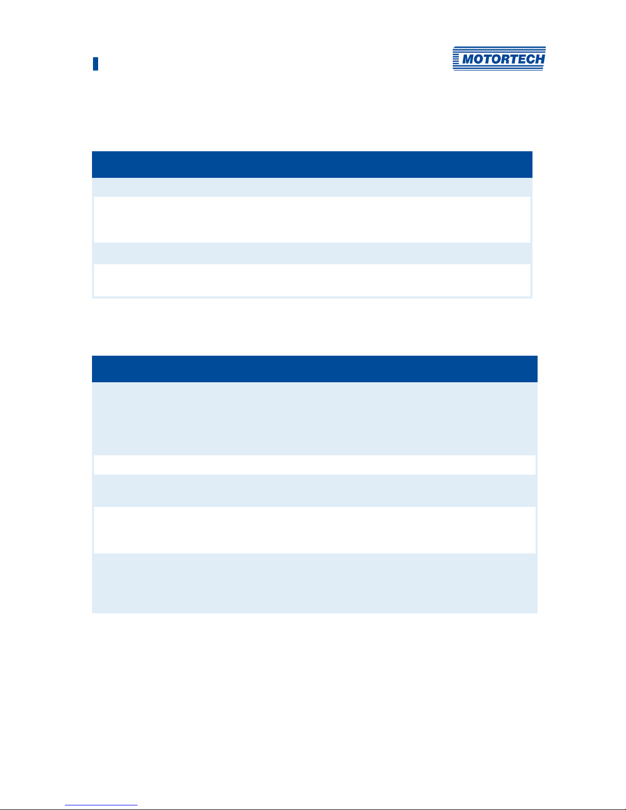
On the device you will find the necessary numbers for a clear product identification:
Example:
DetCon in ATEX-certified enclosure
Abbreviation Description
P/N Part number of the device
S/N Serial number of the device
2019
Y
ear of construction of the device
Page 31
4 Product Description
Rev. 02/2019 31
4.1.5 Electrical Data
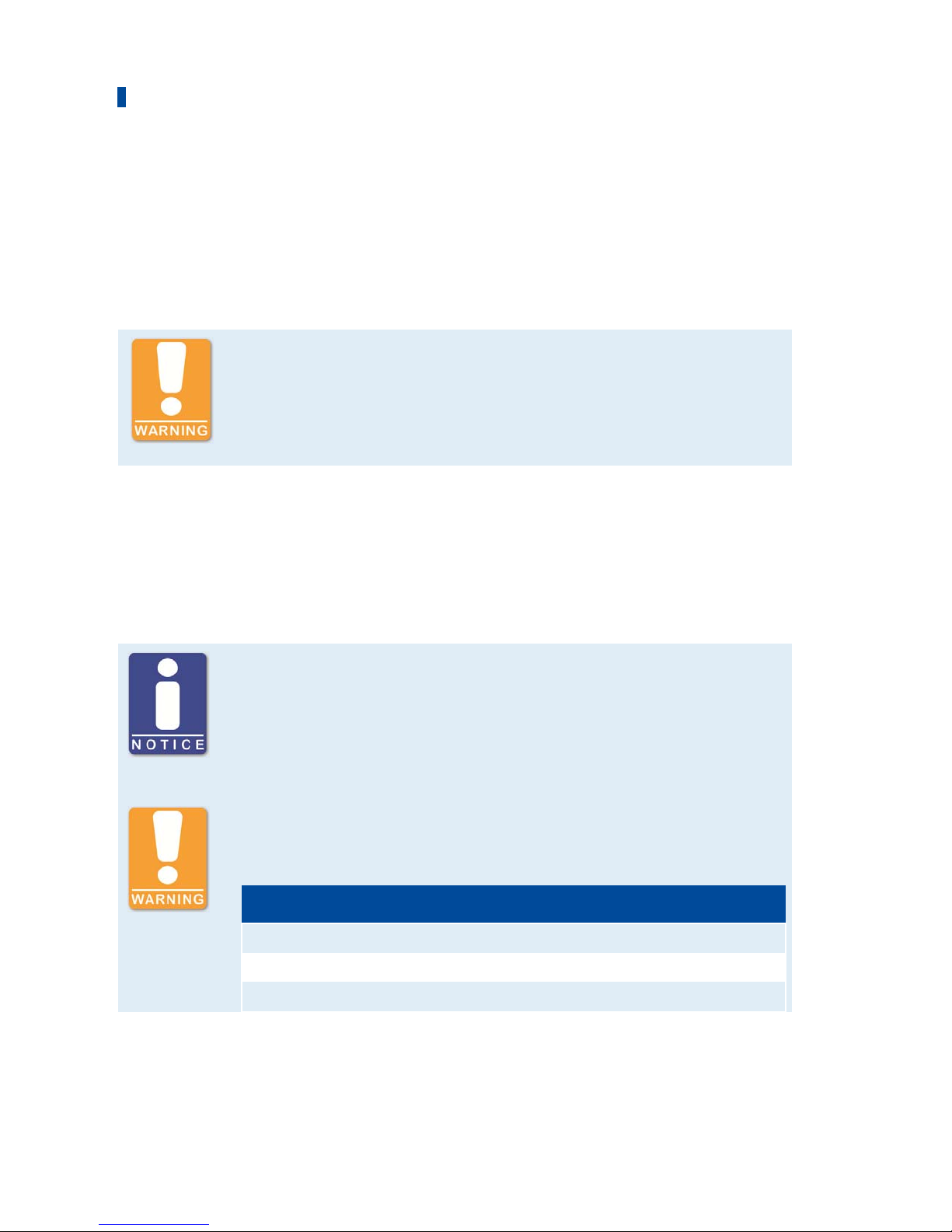
The DetCon has the following electrical characteristics:
Feature Value
Rated current 0.1 A to 0,3 A
Power consumption 0.1 A at 24 V
0.1 A at 36 V
0.3 A at 9 V
Supply voltag 9 V DC to 36 V DC
ATEX: Protective conductor crosssection
4 mm2 to 35 mm2 ( observe EN 60079-0:2014-06, 15.3)
Electrical Data for Inputs and Outputs
The inputs and outputs have the following electrical data:
Inputs and outputs Values
Ignition pulse input Input resistance 220 /1 k
Max. input voltage:
24 V at a load resistance of 220
36 V at a load resistance of 1 k
Max. frequency 800 Hz
Detonation sensor input Input resistance > 1 M
4-20 mA output Max. voltage 30 V
Current accuracy ± 2%
0-5 V output Max. current 2 mA
Voltage accuracy ± 2%
Auxiliary power 5 V DC required
Binary outputs All three outputs share a single connection and are potential-
free (galvanically separated optocouplers).
Max. voltage 33 V
Max. current 50 mA
Page 32
4 Product Description
32 Rev. 02/2019
4.1.6 Interfaces
USB Interface
– Compatible with USB 1.1
– Connector B version
– Transfer rate 1 MBit/s
Danger of explosion!
The USB interface may only be used in a non-hazardous atmosphere. There
is a danger of sparking.
CAN Bus Interface
– Galvanically isolated
– Baud rate 250 kBd
4.1.7 Technical Data of the Detonation Sensors
Use MOTORTECH detonation sensors
DetCon detonation controller systems are parameterized for operation with
MOTORTECH detonation sensors (piezoelectric acceleration transducers).
The use of other sensors entails a new calibration of the engine.
Danger of explosion!
Only use the detonation sensor approved by MOTORTECH and the required
number of blocking capacitor boards for operation in hazardous areas.
P/N Description
43.20.001 Detonation sensor without sensor lead, two-pole
43.30.004-60 Detonation sensor lead, 18 m (59.06 ft)
43.20.029 Blocking capacitor board (ATEX)
Page 33

4 Product Description
Rev. 02/2019 33
The MOTORTECH detonation sensors have the following technical data:
Feature Value
Sensor principle Piezoelectric acceleration transducer
Sensor type MOTORTECH
Frequency range 1 kHz to 20 kHz
Resonance frequency > 20 kHz
Temperature range –40 °C to +130 °C (–40 °F to +266 °F)
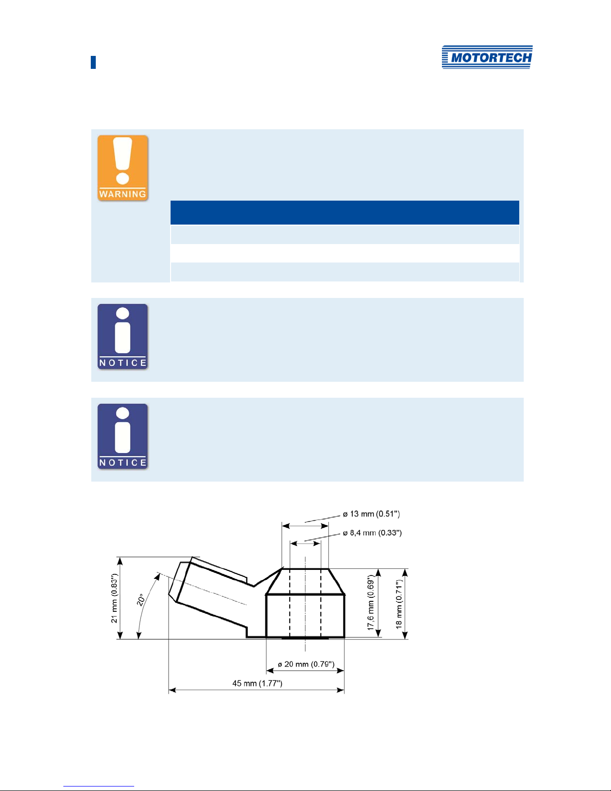
Dimensions, Sensor 45 mm x 20 mm x 21 mm (1,77'' x 0,79'' x 0,83'')
(see Mounting the Knocking Sensors)
Sensor mount Torque: 20 Nm ± 5 Nm (14.8 lb-ft ± 3.7 lb-ft) for the following
fixing screws:
– Cast iron: M8 x 25 mm (0.98"), strength 8.8
– Aluminium: M8 x 30 mm (1.18") , Strength 8.8
Torque: 15 Nm ± 5 Nm (11 lb-ft ±2.2 lb-ft) for the following fixing
screws:
– M6, strength 10.9 with sleeve for fixing to the cylinder head
screw.
If necessary, the material of the cylinder head screw on which
the sensor is mounted should also be taken into account
Blocking capacitor board for use in potentially explosive atmospheres
The blocking capacitor board serves as a safety barrier between the DetCon20 and the
Knock sensors, which makes the use of knock sensors in potentially explosive areas
is made possible.
The blocking capacitor board has the following technical data:
Feature Value
Temperature range –10 °C to +60 °C (+14 °F to +140 °F)
Dimensions (mm) 40 mm x 47 mm x 12 mm (1.57" x 1.85" x 0.019 ")
Flammability class UL 94-V2
Article number P/N 43.20.029
Page 34
4 Product Description
34 Rev. 02/2019
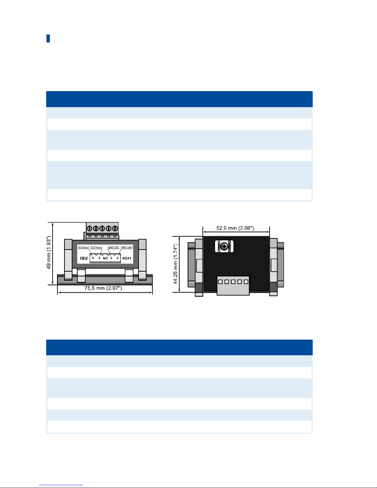
4.1.8 Technical Data of the Ignition Sensor Unit (ISU)
The ignition sensor unit has the following technical data:
Feature Value
Sensor principle Signal transducer
Sensor type MOTORTECH
Voltage
supply
90 V DC to 300 V DC
Temperature range –25 °C to +70 °C (–13 °F to +158 °F)
Dimensions, Sensor 75.5 mm x 44.25 mm x 49 mm (2.97" x 1.74" x 1.93") incl. DIN
rail
(see Mounting the Ignition Sensor Unit (ISU) on page 53)
Sensor mount DIN rail mounting
4.1.9 Technical Data of the Camshaft Sensor
The camshaft sensor has the following technical data:
Feature Value
Sensor principle active, inductive proximity switching sensor
Sensor type MOTORTECH
Voltage
supply
15 to 34 V DC
Temperature range –25 °C to +85 °C (–13 °F to +185 °F)
Dimensions, Sensor M12 x 1 thread; length 60 mm (2.36") or 100 mm (3.94")
Sensor mount Nut M12 x 1
Page 35
4 Product Description
Rev. 02/2019 35
4.1.10 Requirements for External Equipment
External equipment shall fulfill the input and output specifications of the DetCon.
4.1.11 Overview Drawings
DetCon2 – Dimensions
Page 36
4 Product Description
36 Rev. 02/2019
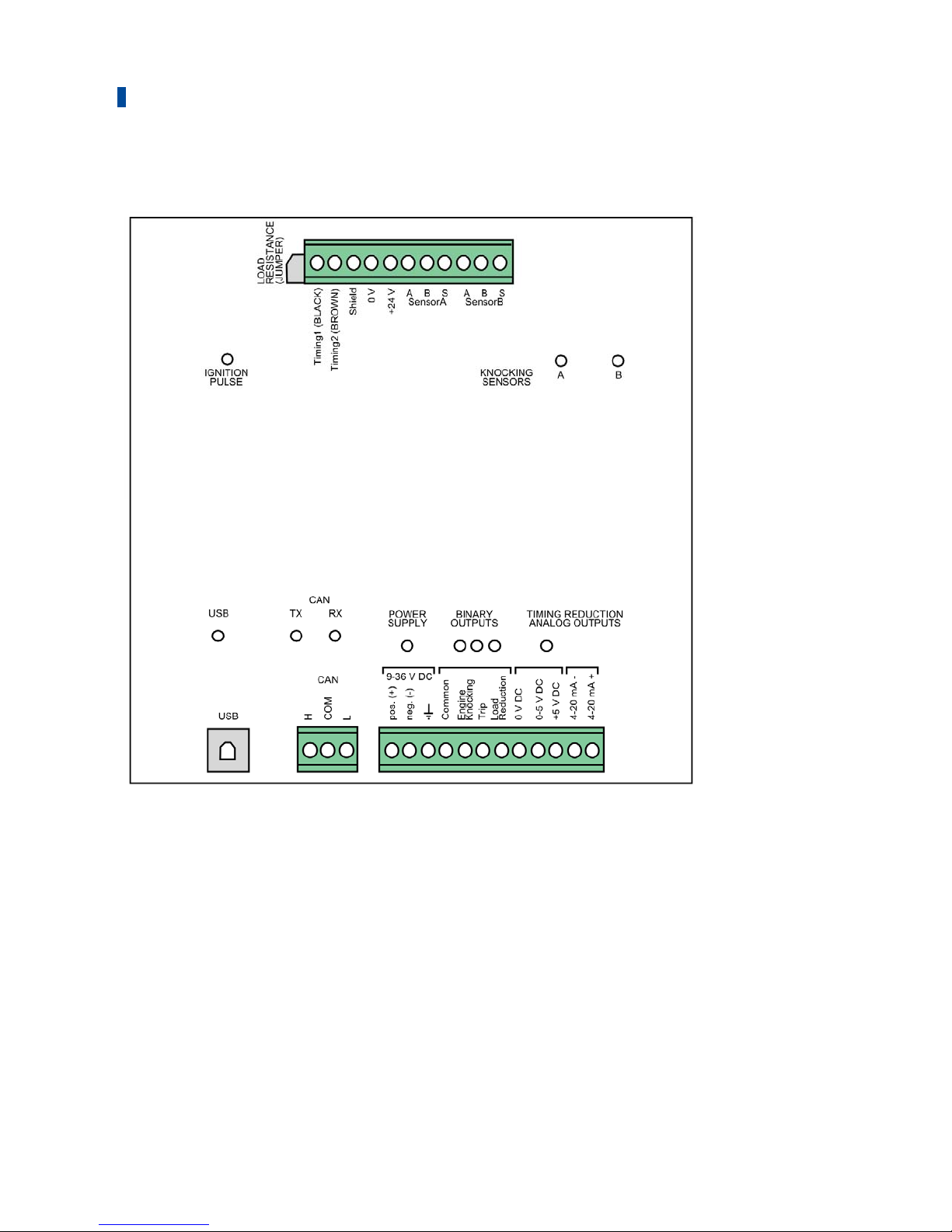
DetCon2 – Ports/Connections and LEDs
For the functions of the individual ports/connections and LEDs, please refer to the table
following the drawings accompanying the DetCon20.
Page 37
4 Product Description
Rev. 02/2019 37
DetCon20 – Dimensions
Page 38
4 Product Description
38 Rev. 02/2019
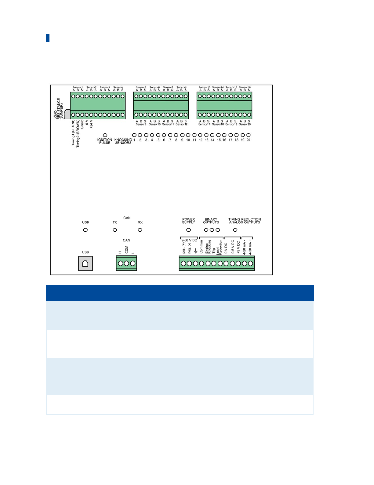
DetCon20 – Ports/Connections and LEDs
Labeling Function
LOAD RESISTANCE Jumper which must be removed if no ignition sensor unit (ISU) is
used (when using a camshaft sensor or MOTORTECH ignition
controllers with ASO output)
Sensor A-B (DetCon2)
Sensor 1-20
(DetCon20)
Connections of the detonation sensors (A=white, B=brown,
S=shield) (see Wiring of the Detonation Sensors on page 57)
Timing1, Timing2,
Shield 0 V, +24 V
Connections for the ignition sensor unit (ISU) or the camshaft
sensor (see Wiring of the Ignition Sensor Unit (ISU) on page 59 or
Wiring of the Camshaft Sensor (for Diesel and Pilot Injection Engines
Only) on page 62)
IGNITION PULSE (LED) This LED flashes when an ignition pulse is transmitted to the
DetCon.
Page 39

4 Product Description
Rev. 02/2019 39
Labeling Function
KNOCKING SENSORS
(LEDs)
The LEDs flash if knocking has been detected on the associated
cylinders. If the checkbox Enable knock LED latch (switch ON/OFF to
reset) is activated in the Output options tab, the LEDs light up
permanently as soon as a knock has occurred, instead of flashing.
In this case the LEDs must also be reset manually (see Tab: Output
Options on page 81 )
USB (LED) This LED flashes when data is being transferred via the USB
connection.
CAN TX and RX (LEDs) These LEDs flash when data is being transferred via the CAN bus
(RX=data is being received, TX=data is being transmitted).
POWER SUPPLY (LED) This LED lights up if the supply voltage is available.
BINARY OUTPUTS
(LEDs)
These LEDs light up if the respective binary output (Engine
Knocking, Trip, Load Reduction) has been activated.
TIMING REDUCTION
ANALOG OUTPUTS
(LED)
This LED lights up if an ignition timing reduction has been executed
via one of the two analog outputs (0-5 V or 4-20 mA).
USB Port for the data transmission to the PC.
CAN (H, COM, L) Port for communication via CAN bus with master control devices
(such as ALL-IN-ONE).
9-36 V DC (pos., neg.,
ground)
Connection for the voltage supply
Common Reference potential for the binary outputs (+ or –)
Engine Knocking, Trip,
Load Reduction
Connections of the binary outputs
0 V DC, 0-5 V DC,
+5 V DC
Connections of the analog 0-5 V output (see Wiring of the Analog
Outputs for Ignition Timing Reduction on page 64)
4-20 mA-, 4-20 mA+ Connections of the analog 4-20 mA output (see Wiring of the Analog
Outputs for Ignition Timing Reduction on page 64)
Page 40
4 Product Description
40 Rev. 02/2019
DetCon Model in Enclosure – Dimensions (CSA Certified)
DetCon variant in ATEX enclosure – Dimensions
Page 41
41 Rev. 02/2019
Unpack the equipment, taking care not to damage it, and ensure that the operating manual is
always stored with the equipment and is easily accessible. Check the contents for completeness
and verify that the device type meets your application requirements.
Scope of Supply
The supply scope of the device consists of the following components:
– DetCon detonation controller
– CD-ROM with software for configuring the device
– USB interface lead for connecting the device to a PC/laptop
– Operating Manual
– additionally provided for the model with enclosure: screw set and screw joints
Installation locations where strong vibrations or ambient temperatures of below –40 °C (–40 °F)
or above +70 °C (+158 °F) are present are not permissible and result in the warranty being
voided.
Danger of explosion!
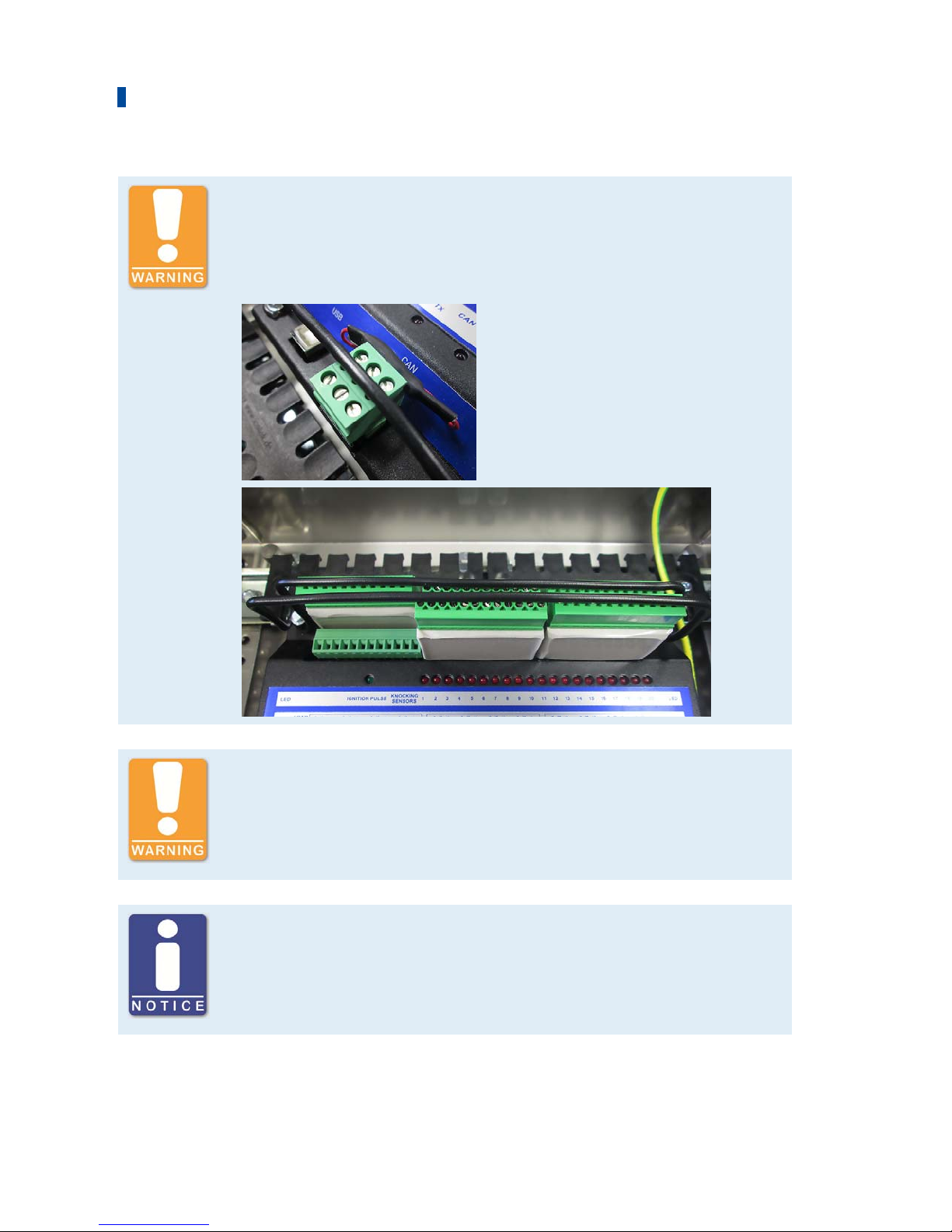
In order to prevent the connection terminals from falling out or loosening,
brackets must be mounted on the DetCon detonation controller in
potentially explosive areas which are screwed over the connection
terminals before commissioning and thus fix them in place. There is a
danger of sparking.
Danger of explosion!
The device may only be installed and operated in hazardous areas in an
environment that ensures pollution degree 2 (or better, danger of leakage
currents) according to IEC/EN 60664-1. There is a danger of sparking
Danger of explosion!
Do not disconnect connections as long as the circuit is active unless the
environment is classified as non-explosive. Refer to the operating
instructions for wiring instructions. There is a danger of sparking.
5 Installation Instructions
Page 42
5 Installation Instructions
42 Rev. 02/2019
ATEX Protection!
Some versions of the ATEX-certified DetCon20 have an external ATEX
protection connected to the CAN bus and the inputs. This external ATEX
protection must not be removed in order to prevent possible flying sparks.
If you do not see this protection externally, it is installed internally.
Risk of Destruction!
When mounting the device, it must be ensured that no vibrations occur
during operation and that temperatures are not exceeded. Otherwise
electronic components can be destroyed. Please read the section
Mechanical data.
Use of wire end sleeves
When connecting the cables to the DetCon detonation controller, use wire
end sleeves to protect the stripped ends.
Page 43
5 Installation Instructions
Rev. 02/2019 43
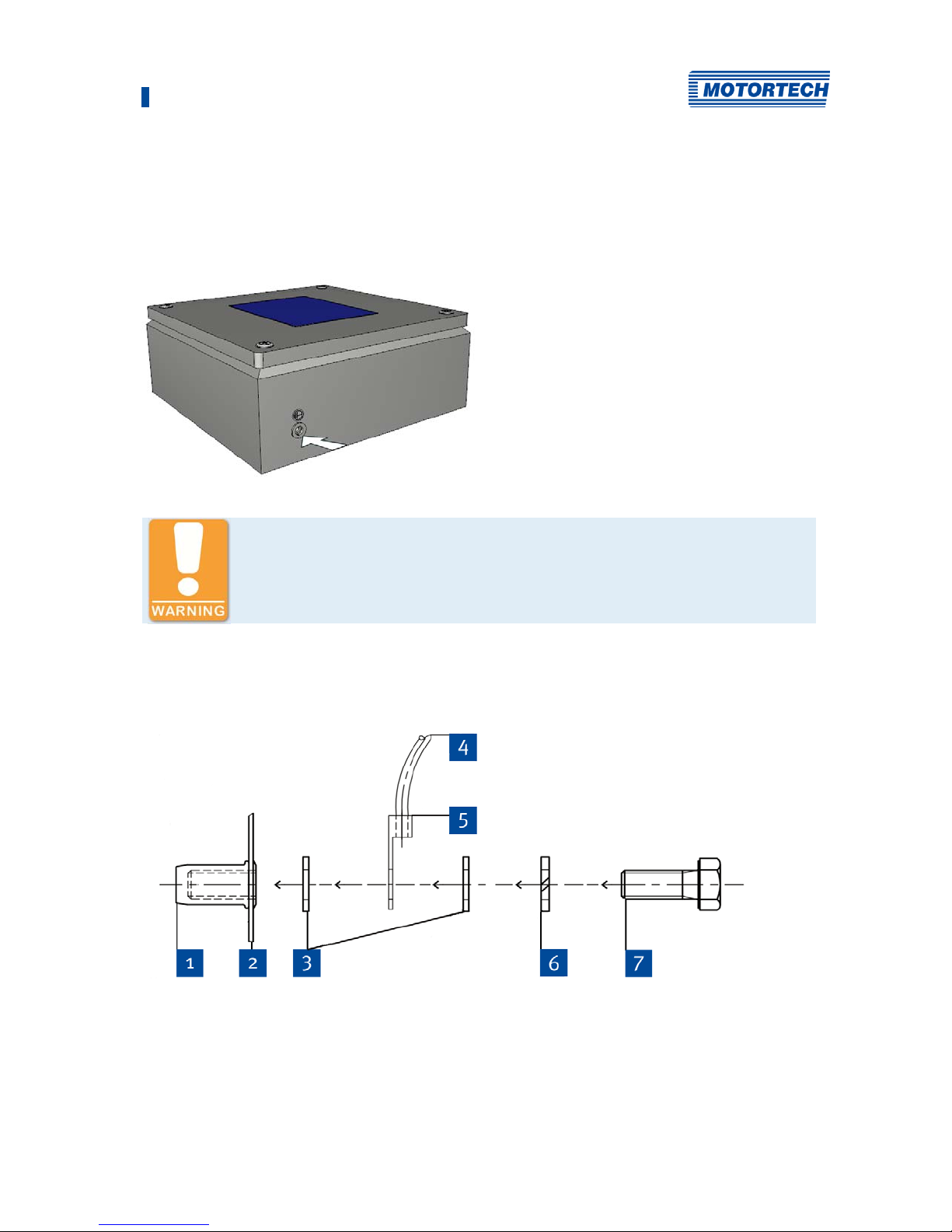
5.1 Ground Connection / Protective Conductor Connection on ATEX Enclosure
The external protective conductor connection is located on the outside of the DetCon20
detonation controller enclosure.
Requirements EN 60439-1:2014-06, 15.3 to be observed!
The external protective conductor must always be connected.
1. Connect the external protective conductor to the corresponding connection as shown in the
following figure.
Page 44
5 Installation Instructions
44 Rev. 02/2019
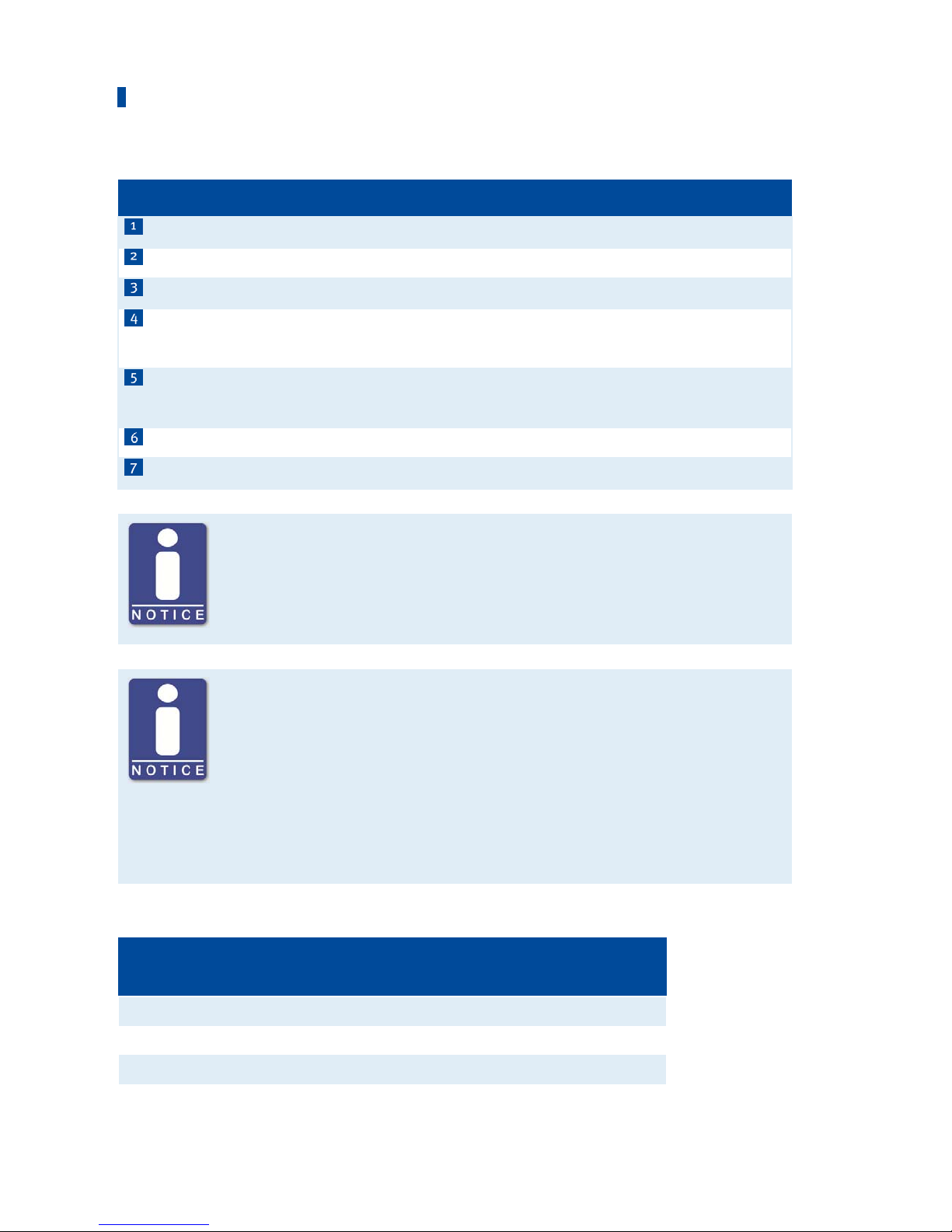
Pos. no Description
Blind rivet nut for M8
Enclosure
Washer ISO 7092-8.4
External protective conductor: Minimum cross section is 4 mm2,
Observe EN 60079-0:2014-06, 15.3!
Ring lead lugs DIN 46234, nominal cross section > 2.5 mm2-35 mm2
Tubular lead lugs DIN 46235, nominal cross section 10 mm2 - 35 mm2
Spring washer DIN 127-B8
Hexagon nut ISO 4017-M8x20
Protective conductor connections of the ATEX enclosure
All protective conductor connections of the ATEX enclosure are designed in
M 8.
Connection of external protective conductor
The external protective conductor is connected with the enclosed stainless
steel screws, nuts, washers and lock washers. The external protective
conductor must be provided with a commercially available lead lug of
suitable cross-section and ring diameter. The lead lugs selected must
comply with one of the following standards:
– DIN 46234 for lead lug
– DIN 46235 for tubular lead lugs
The cross-section for the protective conductor must be dimensioned as follows:
Cross section of phase
conductor S [mm2]
Minimum cross section of corresponding
protective conductor Sp [mm2]
S 16 S
16 < S 35 16
S > 35 0.5 x S
Page 45
5 Installation Instructions
Rev. 02/2019 45
Observe requirements EN 60439-0
– The protective conductor connection parts are designed for a minimum
cross-section of 4 mm2.
– When installing the external protective conductor connection, care
must be taken to ensure that the conductors are secured against
twisting and loosening. This is achieved by professionally and firmly
laying the protective conductors close to the enclosure body.
– Applying a torque of 10 Nm to the screw connection ensures sufficient
contact pressure in conjunction with the enclosed spring washer.
– The choice of materials for the protective conductor connection is such
that electrochemical corrosion is not to be expected. Protective
conductors must be adequately protected against mechanical,
electrodynamic and thermodynamic influences and forces.
– Mechanical connections of protective conductors must be accessible
for inspection and testing.
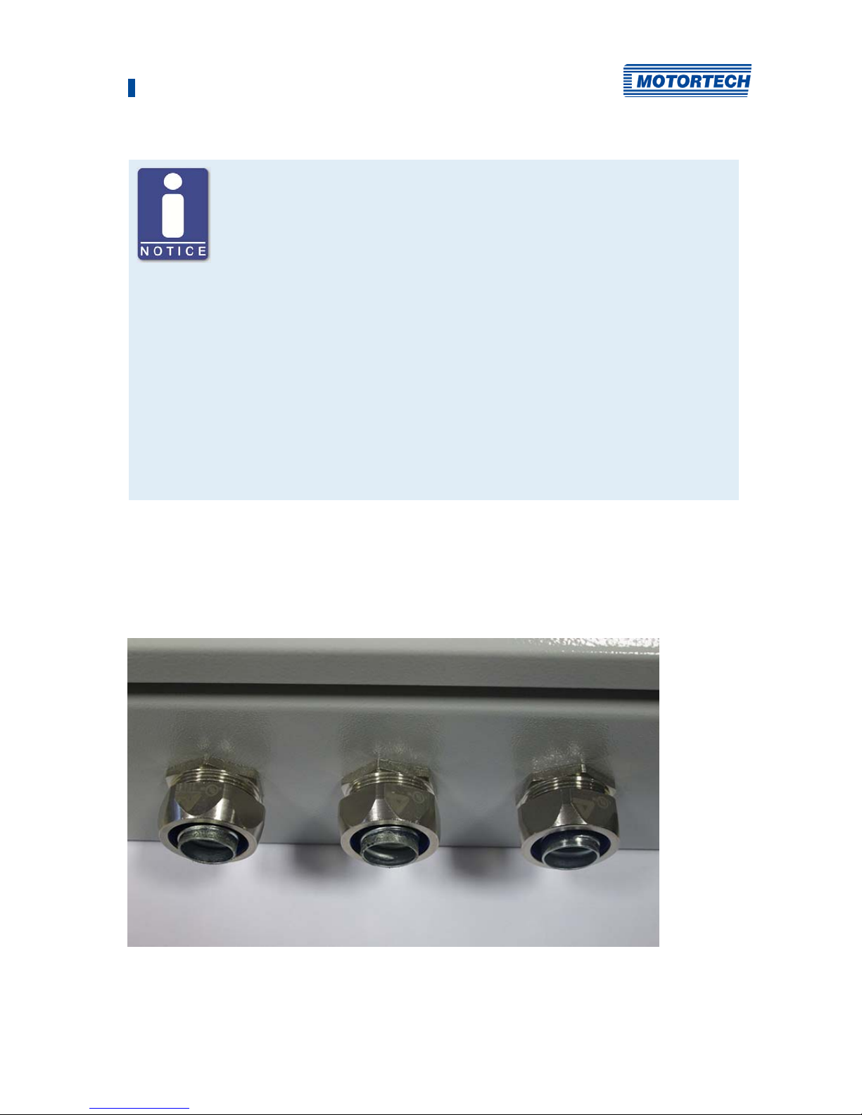
5.2 Lead bushings through the enclosure wall on the ATEX enclosure
In order to be able to connect the DetCon-detonation controller to other devices, the leads must
be conducted through openings in the enclosure wall. This is possible in the form of screw
connections.
Page 46
5 Installation Instructions
46 Rev. 02/2019
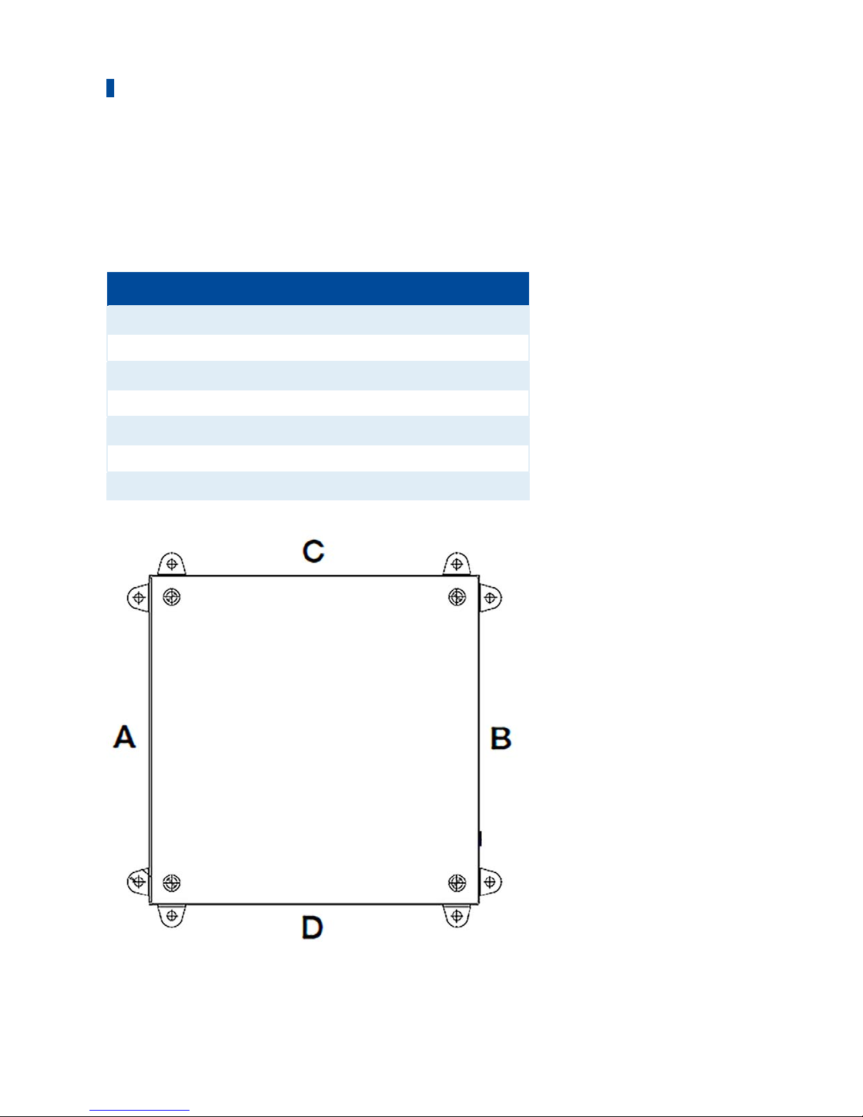
Maximum number of lead bushings
The maximum number of lead bushings depends on their size.
The maximum number for each side of the enclosure is selected according to the following table
so that the side walls are not weakened and the stability of the enclosure is not impaired.
Screw size Side A Side B Side C Side D
M 12 33 31 33 33
M 16 19 17 29 29
M 20 16 14 16 16
M 25 13 11 13 13
M 32 4 2 9 9
M 40 3 1 3 3
M 50 2 1 2 2
Page 47
5 Installation Instructions
Rev. 02/2019 47
Type examination certificate
All lead bushings and cable bushings must have a separate EC type
examination certificate.
Dummy plugs used require a separate EC type examination certificate.
Operational safety
All lead bushings must be mounted with a metal locknut.
When using lead bushings with strain relief and bending protection, the
number of possible standard lead glands is reduced.
Mixed fitting of lead bushings is possible. Areas for intrinsically safe
circuits must be marked separately.
Unused openings for lead bushings must be closed with blind plugs made
of cold impact resistant plastic or metal.
The lead bushings must be mounted in such a way that independent
loosening is prevented and permanent sealing of the lead and lead entry
points can be guaranteed. Lead ties are used for lead fixing.
The spacing of the lead bushings must be selected so that a torque wrench
can be used to tighten the lead bushings and cap nuts. .
Page 48

5 Installation Instructions
48 Rev. 02/2019
Tightening torques
The tightening torques must be observed when installing the cable bushings. If no specific
information is available, the following values must be used.
Size Tightening torque
of connecting piece
[Nm (lb-ft)]
Tightening torque of
cap nuts [Nm (lb-ft)]
Tightening torque of
locknut [Nm (lb-ft)]
Coreperforateddiameter
[mm]
Brass Polyamide Brass Polyamide Brass Polyamide
M 12x1.5 2.5
(1.8)
2.5
(1.8)
2.0
(1.48)
2.0
(1.48)
2.5
(1.8)
2.5
(1.8)
12.5
M 16x1.5 4.0
(2.95)
4.0
(2.95)
2.5
(1.8)
2.5
(1.8)
4.0
(2.95)
4.0
(2.95)
16.5
M 20x1.5 4.0
(2.95)
4.0
(2.95)
2.5
(1.8)
3.5
(2.58)
4.0
(2.95)
4.0
(2.95)
20.5
M 25x1.5 7.5
(5.53)
7.5
(5.53)
12.0
(8.85)
5.0
(3.69)
7.5
(5.53)
7.5
(5.53)
25.5
M 32x1.5 7.5
(5.53)
7.5
(5.53)
12.0
(8.85)
12.0
(8.85)
7.5
(5.53)
7.5
(5.53)
32.5
M 40x1.5 7.5
(5.53)
7.5
(5.53)
12.0
(8.85)
12.0
(8.85)
7.5
(5.53)
7.5
(5.53)
40.5
M 50x1.5 7.5
(5.53)
7.5
(5.53)
12.0
(8.85)
12.0
(8.85)
7.5
(5.53)
7.5
(5.53)
50.5
Page 49
5 Installation Instructions
Rev. 02/2019 49
5.3 Mounting the Detonation Sensors
Danger of explosion!
Only use the detonation sensor approved by MOTORTECH and the required
number of blocking capacitor boards for operation in hazardous areas.
P/N Description
43.20.001 Detonation sensor without sensor lead, two-pole
43.30.004-60 Detonation sensor lead, 18 m (59.06 ft)
43.20.029 Blocking capacitor board (ATEX)
Use MOTORTECH detonation sensors
DetCon detonation controller systems are parameterized for operation with
MOTORTECH detonation sensors (piezoelectric acceleration transducers).
The use of other sensors entails a new calibration of the engine.
Observe the instructions of the engine manufacturer
The following mounting instructions are for orientation only. In any case,
observe the instructions of the respective engine manufacturer for the
installation of detonation sensors and the installation of detonation
controllers.
Dimensions of the Sensor
Page 50
5 Installation Instructions
50 Rev. 02/2019
Dimensions of the Required Bore
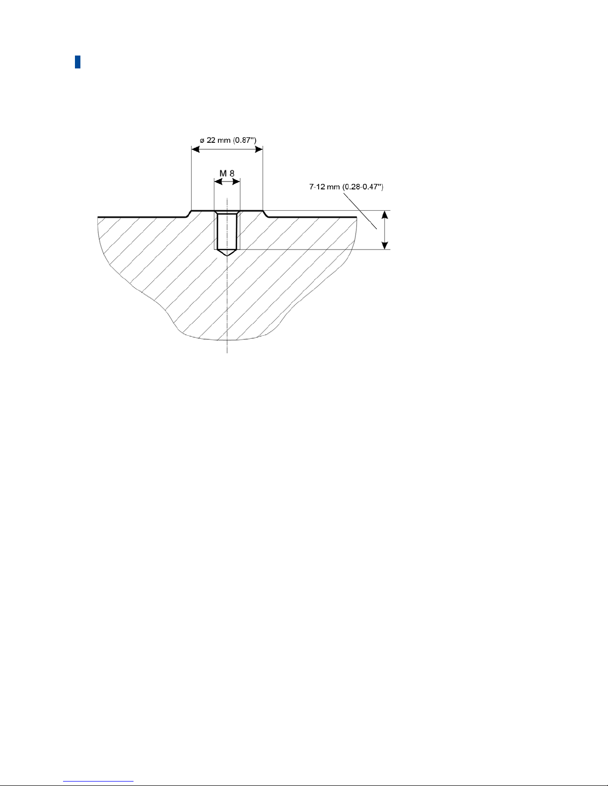
An M6 screw can also be used as an alternative to M8 screw for the mounting of the detonation
sensor. In this case, however
, an adapter sleeve must be used in the sensor to close in the
resultant hollow space, thus ensuring optimal signal transmission.
Mounting
In order to ensure the best functioning of the DetCon detonation controller, it is mandatory to
install the sensors as follows:
– There must be a direct connection to the engine block.
– Installations without a direct connection to the engine block (e. g. with sealings) are
unsuitable.
– Only the metal surface of the sensor may rest on the engine.
– Do not use washers, spring washers, or toothed washers.
– The knocking sensors may not come into contact with liquids (e. g. oil, coolant, water) over a
longer period of time
Page 51
5 Installation Instructions
Rev. 02/2019 51
Risk of Destruction!
The fastening screws of the knock sensors must not be tightened too much,
otherwise the sensors will be damaged and will no longer function properly.
Observe the following information for sensor mounting:
– Torque: 20 Nm ± 5 Nm (14.8 ± 3.7 lb-ft) for mounting screws:
– made of cast iron: M8 x 25 mm (0.98"), Strength: 8.8
– aluminium: M8 x 30 mm (1.18"), strength: 8.8
– Torque: 15 Nm ± 5 Nm (11 lb-ft ±2.2 lb-ft) for M6 fixing screws, strength
10.9 with sleeve .
The torque for mounting in the case of mounting with M8 screws (strength 8.8) is 20 Nm ±5 Nm
(14.8 lb-ft ±3.7 lb-ft) and with M6 screws (strength 12.9) with sleeve 15 Nm ±3 Nm (11 lb-ft ±
2,2 lb-ft).
Also, lay the sensor cables in such a way that no resonance vibrations can occur on the cable.
Otherwise, there is a risk of breakage.
The required mounting of the knocking sensors may vary depending on the engine type used.
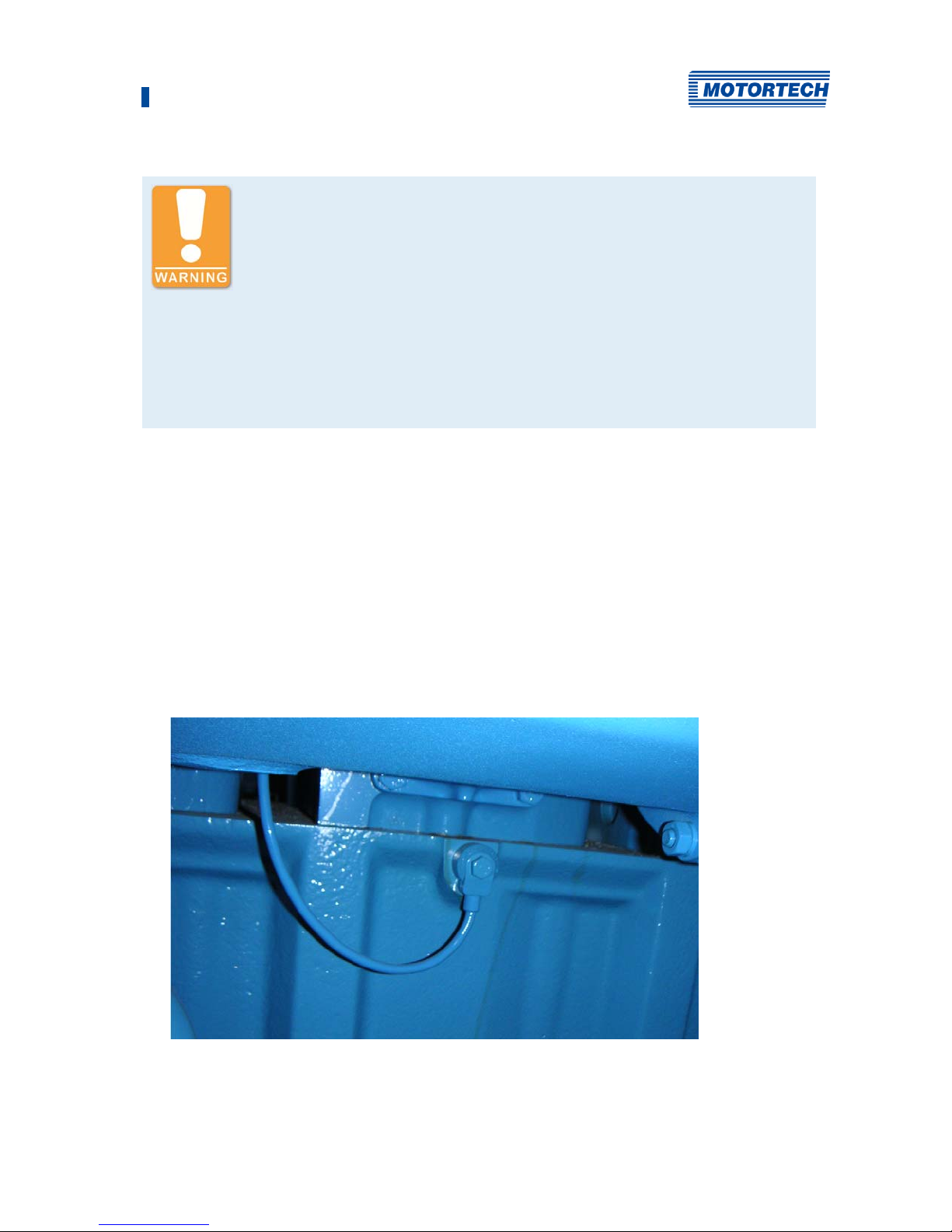
The following locations are, in principle, possible for fitting the knocking sensors taking into
account the aforementioned specifications
– On the engine block
For mounting on the engine block use screws of the type M 8x30-8.8 (AL-engine block) or
M 8x25-8.8 (CI-engine block).
Page 52
5 Installation Instructions
52 Rev. 02/2019
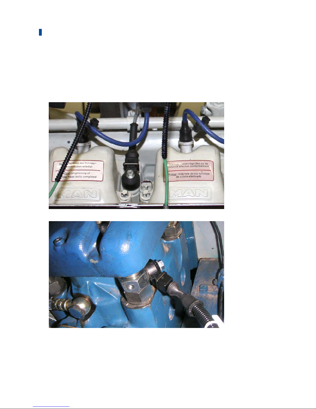
– On the cylinder head screws
Especially when it comes to engine conversions, it has proven to be worthwhile to attach the
knocking sensors on cylinder head screws or -bolts.
Drill an M6-hole with a maximu
m depth of 12 mm (0.47") in the cylinder head screw and fix
the detonation sensor with a screw of type M 6x25-10.9 and an adapter sleeve to fill the
hollow space
– On the nuts o
f the cylinder head studs
Contact the engine manufacturer if
you are not sure whether the cylinder head screw is suitable
for the installation.
Page 53
5 Installation Instructions
Rev. 02/2019 53
Mounting the blocking capacitor board for use in hazardous areas
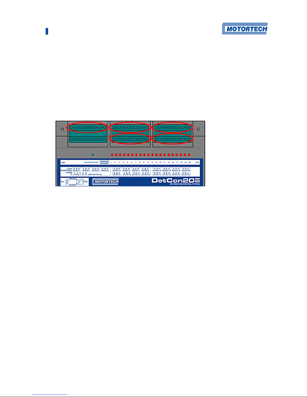
A blocking capacitor board has four outputs. If all 20 possible knock sensor inputs are used with
a DetCon20, then five blocking capacitor boards are required.
One blocking capacitor board is used for each of the four knock sensors required.
1. Plug the required blocking capacitor boards into the connectors (marked red in the figure)
for the knock sensors on the DetCon20.
2. The wiring of the knock sensors has to be done as described above, with the difference that
you now use the connector plug on the blocking capacitor board.
Page 54
5 Installation Instructions
54 Rev. 02/2019
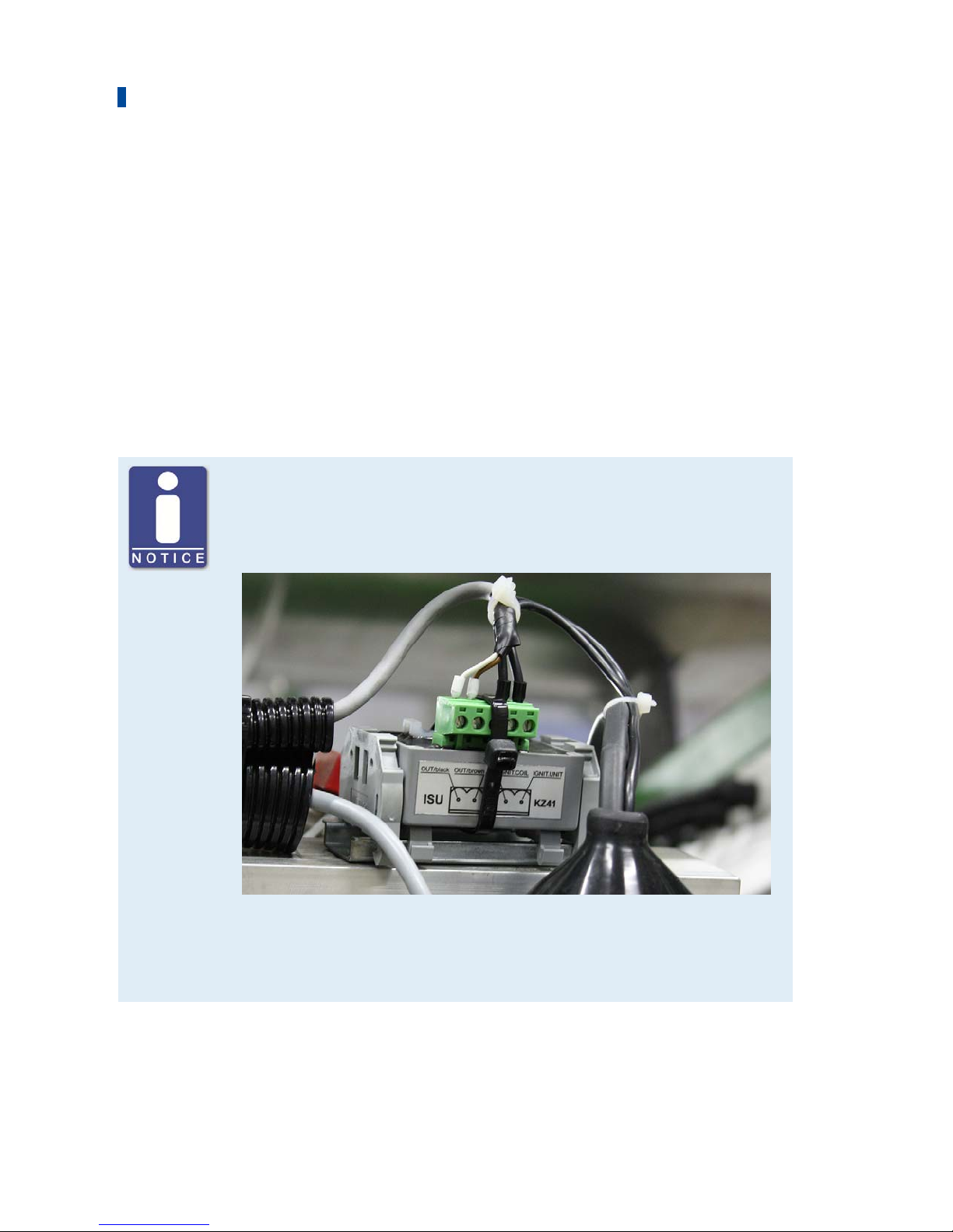
5.4 Mounting the Ignition Sensor Unit (ISU)
The ignition sensor unit is mounted on a DIN rail on the engine in direct proximity to the ignition
coil of the first cylinder in the firing order, which is equipped with a detonation sensor or in the
vicinity of the ignition controller.
For information on wiring connections, please refer to section Wiring of the Ignition Sensor Unit
(ISU) on page 59.
For diesel and pilot injection engines, a camshaft sensor is used instead of an ignition sensor
unit (ISU). Refer to the section Mounting the Camshaft Sensor on page 55. No ignition sensor
unit is needed when using a MOTORTECH ignition sensor unit with ASO (e. g. MIC6) output
either. You can find information in the section Wiring for Ignition Controller with ASO Output on
page 58.
Mounting on the engine
The ignition sensor unit is fully sealed and therefore resistant to vibrations.
When mounting on the engine or in an environment in which vibrations
arise, only the connector must be secured e.g. by means of a cable tie.
Please note that the contacts of the connector are bare and must be
protected against moisture and contamination. If the engine should be in
such a location, the ignition sensor unit can be, for example, mounted in a
junction box or housed in a control cabinet.
Page 55
5 Installation Instructions
Rev. 02/2019 55
No ignition sensor unit is required for the ASO output
If you use a MOTORTECH ignition controller (e. g. MIC6) with auxiliary
synchronization output (ASO), you do not need any ignition sensor unit
(ISU). In this case, the ignition pulse is transmitted to the DetCon via the
ASO output.
Overview of Use: Ignition Sensor Unit and Load Resistance Jumper
The following table provides an overview of the applications for which you
must use the ignition sensor unit (ISU) and when the jumper Load
Resistance on the DetCon device must be removed:
Pilot injection
or diesel engine
Gas engines
Without ASO
output (e. g.
MIC500)
With ASO output
(e. g. MIC850,
MIC6)
Ignition sensor unit (ISU)
required
No
Y
es No
Jumper Load
Resistance
Remove jumper Jumper set Remove jumper
Page 56
5 Installation Instructions
56 Rev. 02/2019
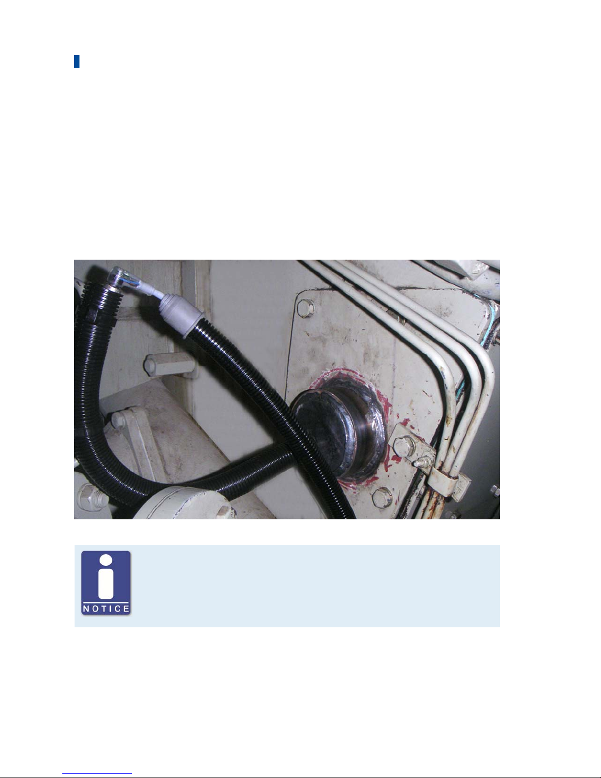
5.5 Mounting the Camshaft Sensor
In diesel and pilot injection engines, camshaft sensors are used to determine the fuel injection
timing instead of the ignition sensor units used for gas engines. The camshaft must be prepared
in such a way that the inductive camshaft sensor receives the rising signal at the injection point
(+/- 5°). Mounting possibilities allowing for the reception of the required signal differ according
to the engine type. It may be necessary, for example, to insert a screw or drill a hole into the
camshaft or install a trigger wheel.
It is possible to install PNP and NPN sensors. In both cases, the input resistance must be 1 k
(i. e. the Load Resistance jumper is removed). The following photo shows an example of such an
installation.
Calibration for diesel and pilot injection engines
For diesel and pilot injection engines, calibration must be performed by
MOTORTECH service personnel.
Page 57

57 Rev. 02/2019
Tightening torque of the connection terminals
The tightening torque for the connection terminals in the DetCon is 0.5 Nm.
6.1 Wiring of the Detonation Sensors
Mount the detonation sensors in accordance with the firing order of the cylinders. To do this,
enter the firing order of your engine in the following table and connect the sensors with the
assigned cylinders and the corresponding inputs on the DetCon according to the resulting
sequence.
If all cylinders are not fitted with detonation sensors, the first detonation sensor is assigned to
the first cylinder used in the firing order. For example, if only the 3rd and 5th cylinders in the
firing order are provided with detonation sensors, the first detonation sensor is mounted on the
3rd cylinder and the first detonation sensor input is connected to the DetCon.
Sensor/ Input
on DetCon
Firing order
of cylinders
Sensor/ Input
on DetCon
Firing order
of cylinders
1
11
2
12
3
13
4
14
5
15
6
16
7
17
8
18
9
19
10
20
6 Wiring of the Device
Page 58
6 Wiring of the Device
58 Rev. 02/2019
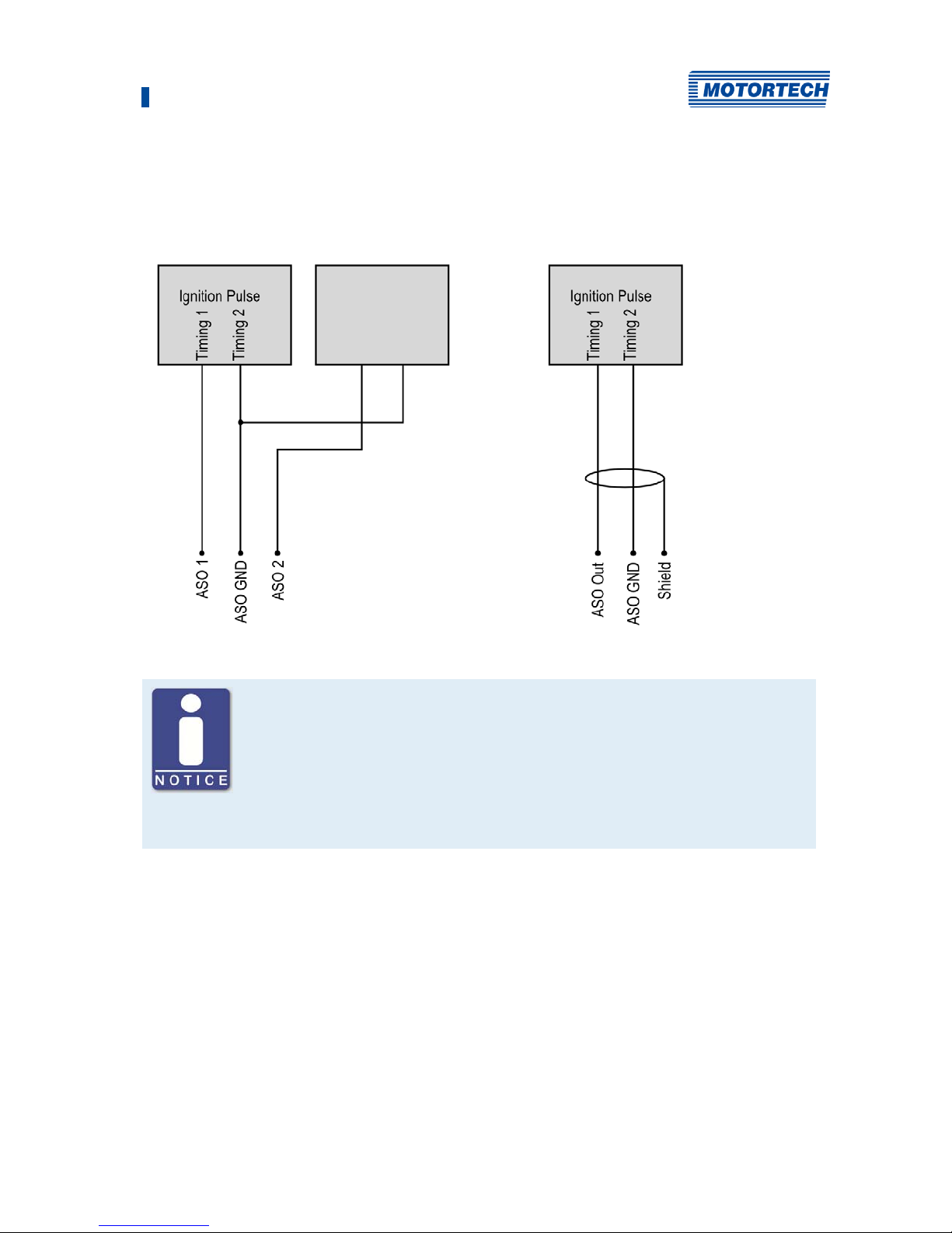
6.2 Wiring for Ignition Controller with ASO Output
No ignition sensor unit (ISU) is required when you use the ignition controller with ASO output
from MOTORTECH (e. g. MIC6). In this case, the ignition pulse is transmitted to the DetCon via
the auxiliary synchronization output (ASO). The jumper identified with Load Resistance must be
removed.
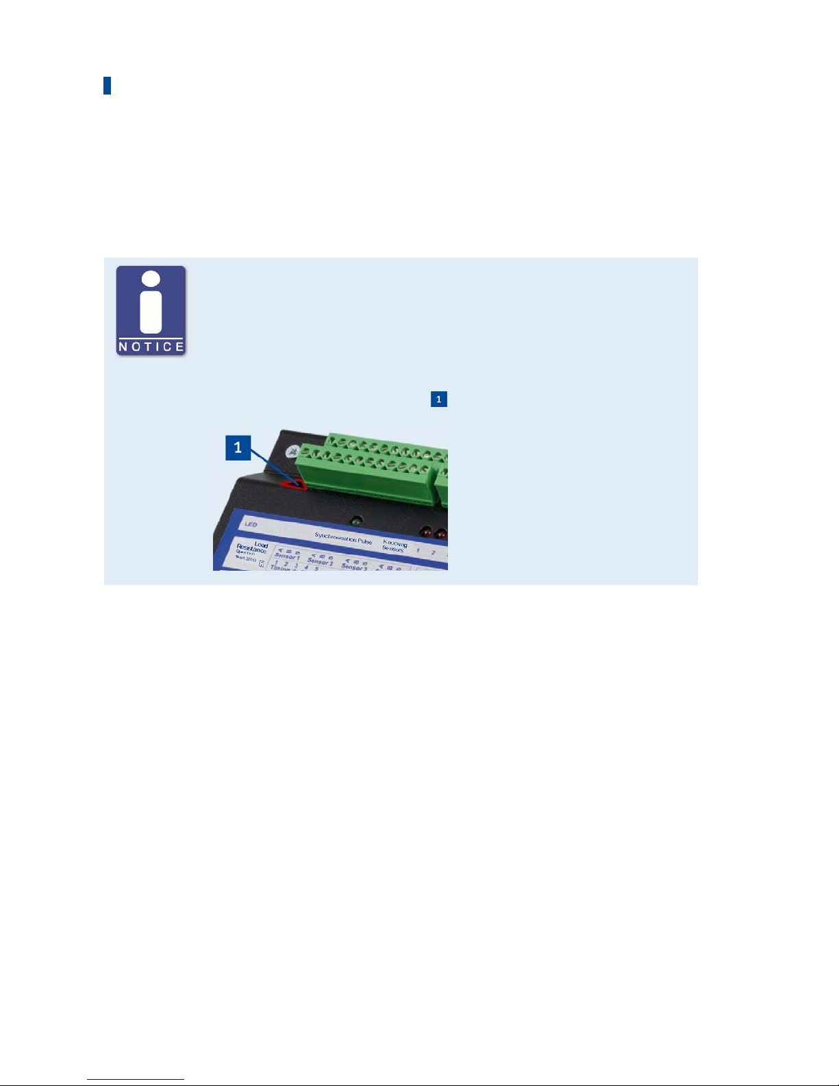
Position Load Resistance Jumper
The jumper Load Resistance changes the input resistance of the ignition
input.
– Jumper set: 220
– Jumper removed: 1 k
It is on the upper left of the device .
Page 59
6 Wiring of the Device
Rev. 02/2019 59
The connection between DetCon and the ignition controllers with ASO output is established as
follows:
DetCon other equipment DetCon
MIC850 connection MIC3, MIC4, MIC5, MIC6 connection
Configuration of the ignition controller
In the configuration software (MICT) for the MOTORTECH ignition controllers
with ASO output, the adjustments for the DetCon can be easily made using
the button Configuration for DetCon2/20. This can be found on the
configuration page Input/Outputs – ASO1 (auxiliary synchronization
output). Further information can be found in the operating manual of your
ignition controller.
Page 60
6 Wiring of the Device
60 Rev. 02/2019
6.3 Wiring of the Ignition Sensor Unit (ISU)
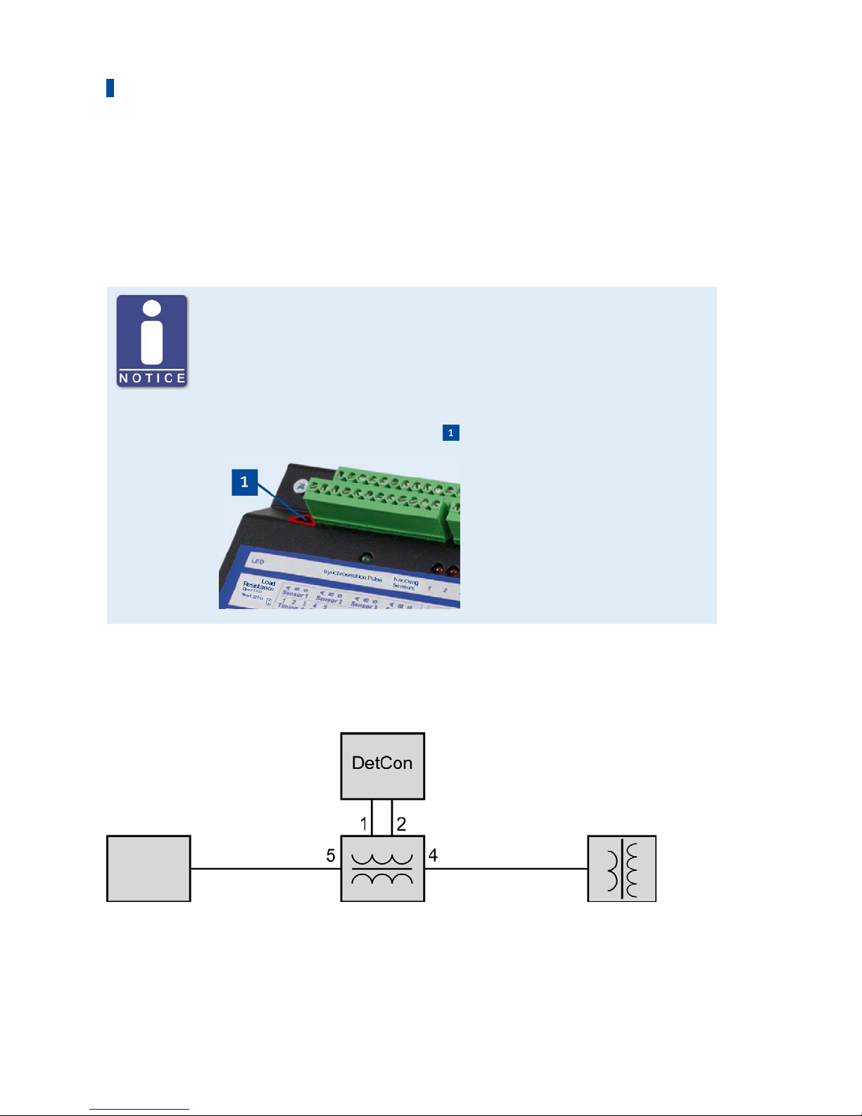
In order to transfer the ignition pulse of the first cylinder in the firing order to the ignition input
of the DetCon, the ignition sensor unit (ISU) is installed between the ignition output of the first
cylinder and the primary side of the ignition coil of the first cylinder. The jumper with the
designation Load Resistance must not have been removed.
Position Load Resistance Jumper
The jumper Load Resistance changes the input resistance of the ignition
input.
– Jumper set: 220
– Jumper removed: 1 k
It is on the upper left of the device .
If not all cylinders are fitted with detonation sensors, the ignition sensor unit is mounted on the
cylinder on which the first detonation sensor is mounted.
Principle Circuit Diagram
Ignition
controller
Ignition output
1st cylinder
Ignition sensor unit (ISU)
Primary side of
ignition coil
1st cylinder
Ignition coil
1st cylinder
Page 61
6 Wiring of the Device
Rev. 02/2019 61
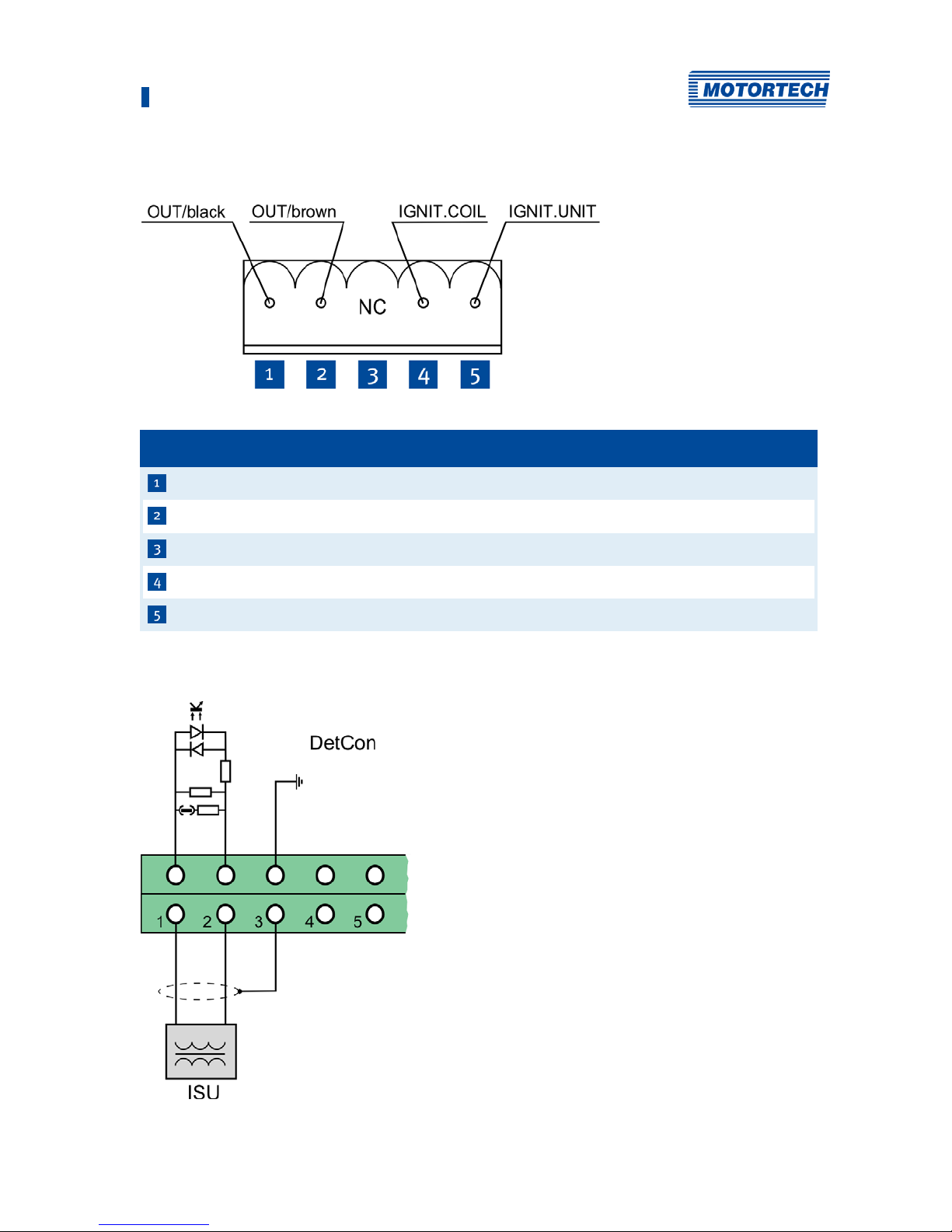
Connections on the Ignition Sensor Unit
No. Connection
DetCon ignition input (Timing1, black)
DetCon ignition input (Timing2, brown)
Not used
Primary side of ignition coil of first cylinder
Ignition controller ignition output of the first cylinder
Connections on the DetCon
The ignition sensor unit is connected to the DetCon via the connector Ignition Pulse.
Page 62
6 Wiring of the Device
62 Rev. 02/2019
6.4 Wiring of the Camshaft Sensor (for Diesel and Pilot Injection Engines Only)
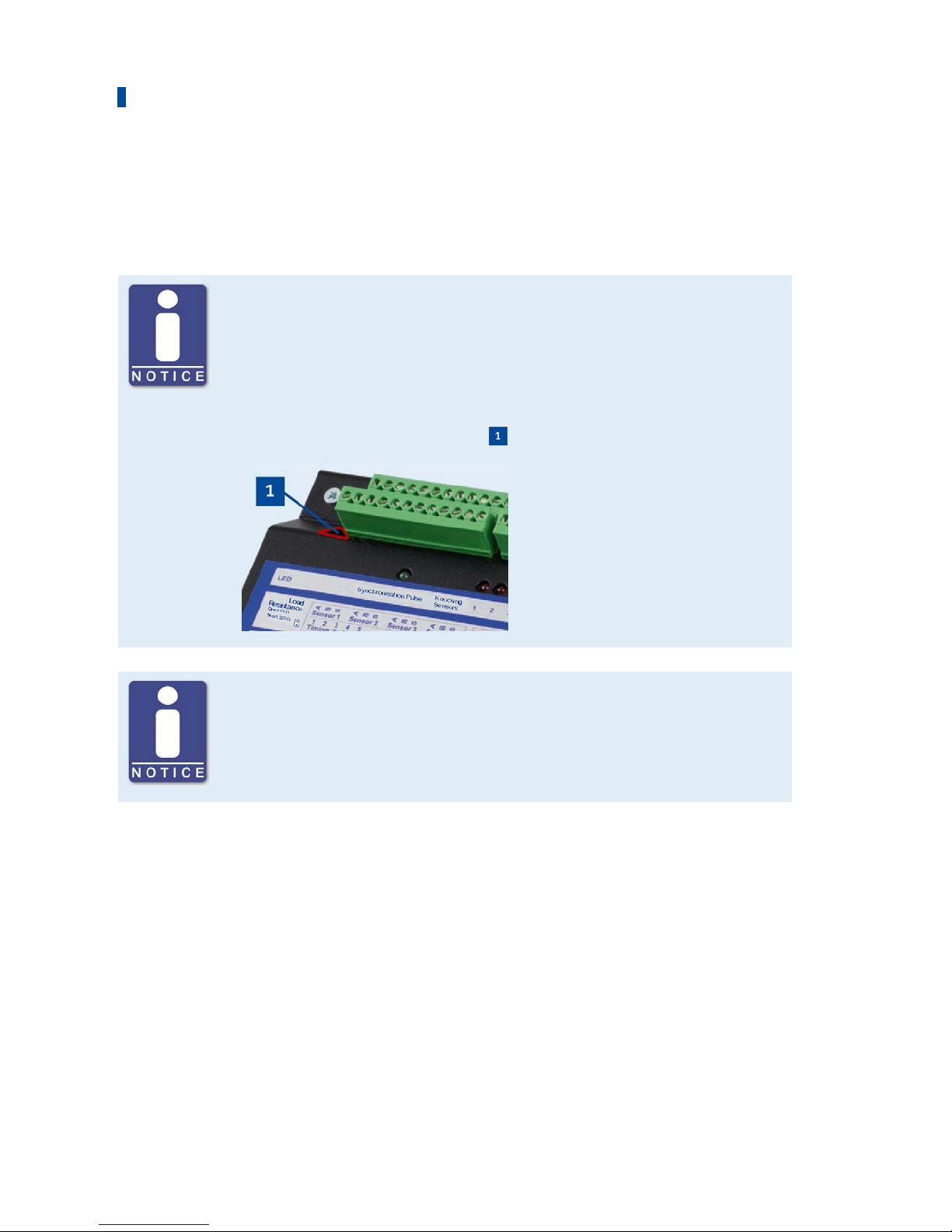
When using a camshaft sensor, the jumper with the designation Load Resistance must be
removed.
Position Load Resistance Jumper
The jumper Load Resistance changes the input resistance of the ignition
input.
– Jumper set: 220
– Jumper removed: 1 k
It is on the upper left of the device .
Calibration for diesel and pilot injection engines
For diesel and pilot injection engines, calibration must be performed by
MOTORTECH service personnel.
Page 63

6 Wiring of the Device
Rev. 02/2019 63
Connections on the DetCon
The ignition sensor unit is connected to the DetCon via the connector Ignition Pulse.
– NPN sensor connection
– PNP sensor connection
Page 64
6 Wiring of the Device
64 Rev. 02/2019
6.5 Wiring of the Binary Outputs
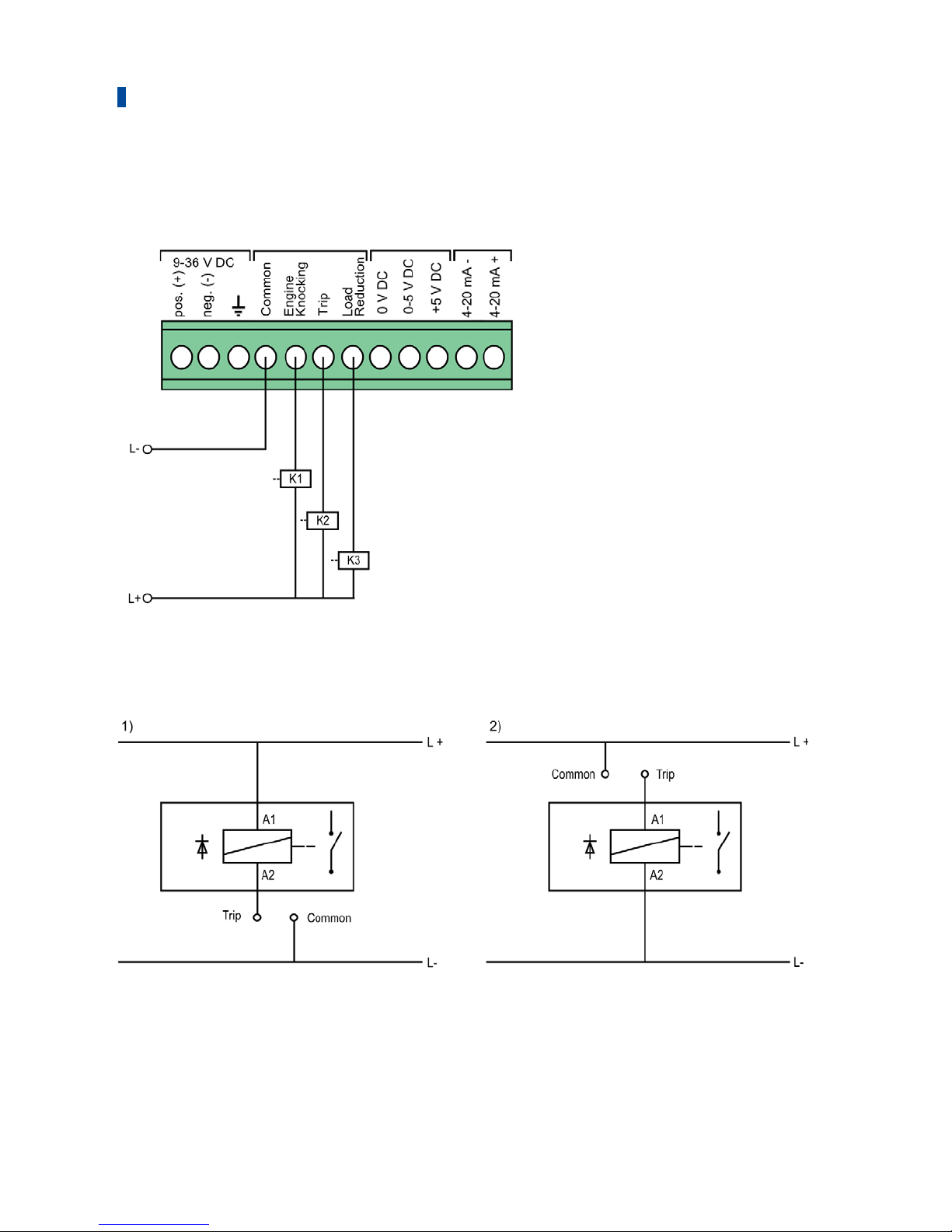
Example Configuration
K1 = Relay Engine Knocking (Knocking
Warning)
K2 = Relay Trip (Engine Stop)
K3 = Relay Load Reduction
The following illustrations show examples of two alternatives for wiring the output Trip.
Page 65
6 Wiring of the Device
Rev. 02/2019 65
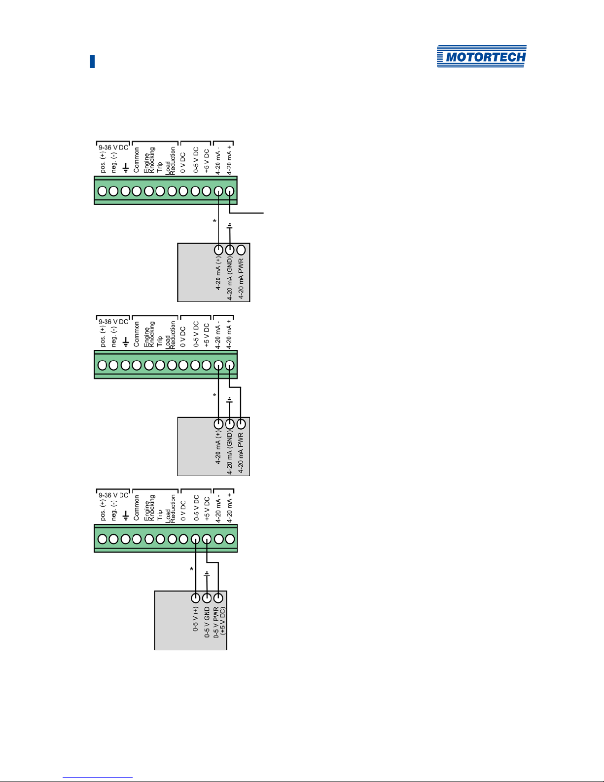
6.6 Wiring of the Analog Outputs for Ignition Timing Reduction
4-20 mA
Output co
nnector on the DetCon
+24 V DC supply voltage
Connection on the Ignition Controller
* 4–20 mA signal
Alternative
Output co
nnector on the DetCon
Connection on the Ignition Controller
* 4–20 mA signal
0-5 V
Output co
nnector on the DetCon
Connection on the Ignition Controller
* 0–5 V signal
The precise connection assignment on the ignition controller can be found in section Input
Wiring – Ignition Timing & Safety Devices in the operating manual for your MOTORTECH ignition
controller.
Page 66
6 Wiring of the Device
66 Rev. 02/2019
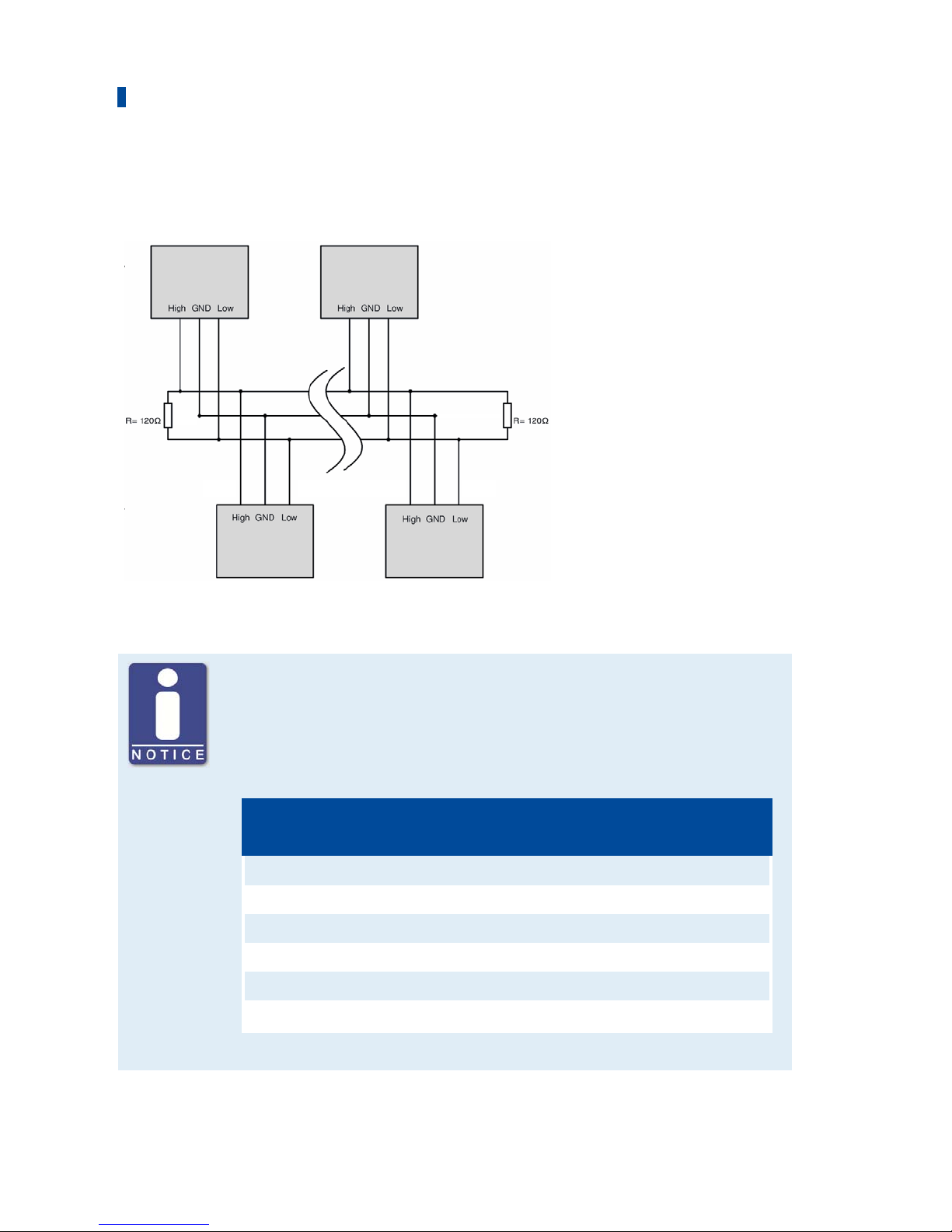
6.7 Wiring CAN Bus
First device Second-to-last device
Second device Last device
CAN bus wiring
Note the following when connecting the CAN bus:
– Each bus end must be fitted with a terminating resistor of 120 Ω (see
drawing).
– The maximum wire length depends on the bit rate:
Bit rate Maximum wire
length
Maximum length
of a stub
Maximum length of
all stubs
1 Mbit/s 25 m (82') 1.5 m (5') 7.5 m (25')
800 kbit/s 50 m (164') 2.5 m (8') 12.5 m (41')
500 kbit/s 100 m (328') 5.5 m (18') 27.5 m (90')
250 kbit/s 250 m (820') 11 m (36') 55 m (180')
125 kbit/s 500 m (1,640') 22 m (72') 110 m (360')
50 kbit/s 1,000 m (3,280') 55 m (180') 275 m (902')
– Only use cables that are specified by the manufacturer for CAN bus.
Page 67

67 Rev. 02/2019
7.1 Ignition Timing Reduction
The DetCon has two analog outputs for ignition timing reduction:
– 4-20 mA current loop
– 0-5 V voltage output
Both analog outputs operate simultaneously. Use the output designated for ignition timing
reduction for the ignition controller you are using (if necessary, ask the manufacturer of the
ignition system).
The analog outputs change their values and thereby retards the ignition timing as soon as the
IGNITION REDUCTION LIMIT has been exceeded. This limit is specified via the DenEdit software.
In addition, the software is used to determine the extent to which the ignition timing is retarded
(Timing reduction gain) and how quickly the ignition timing retarding is reset when knocking is
not longer detected (Decrease ramp). The retarding of the ignition timing can be limited using
the analog outputs via the Maximum output value.
7.2 Load Reduction
If the ignition timing can no longer be corrected via the analog outputs and the engine is still
knocking, the binary output for load reduction (LOAD REDUCTION) is activated. A master control
(e.g. ALL-IN-ONE) can control the engine power via this output.
LOAD REDUCTION is deactivated again if the engine knocking stops.
7.3 Engine Stop
The binary output TRIP is activated when engine knocking exceeds the maximum value
Immediate stop limit. This value is specified via the DenEdit software. The output can be used as
an emergency stop signal.
Checkbox Enable bad sensor detect
Activate the checkbox so that faulty knock sensors are indicated by the BAD
SENSOR status display. This function only detects sensors that supply
faulty signals. If there is a cable break or a sensor does not supply a signal
at all for any other reason, this is not indicated. If a faulty sensor is
detected, the binary output TRIP is also switched..
7 Functions
Page 68

68 Rev. 02/2019
You can configure the DetCon detonation controller and display the current knocking values of
the engine using the DenEdit software application. The device can be operated via the software
in three different basic modes:
– Measurement mode
– Interface diagnostics mode
– Knock detection mode
Measurement Mode
The measurement mode is used for engine calibration. Calibration is only required for engine
types for which a parameter file has not yet been created and is executed by MOTORTECH service
personnel.
Interface Diagnostics Mode
The interface diagnostics mode can be used to test the output signals at the binary and analog
inputs. The values set in the area Diagnose in the tab Mode are transmitted to the outputs of the
device. Knocking analysis is not carried out.
Knock Detection Mode
Knock detection mode is the operation mode of the detonation controller. After synchronization,
the signals of the knocking sensors are analyzed and output signals are generated accordingly
for the binary and analog outputs. The condition of the outputs are indicated via LEDs and the
signals of the detonation sensors are displayed in the tabs for process monitoring. Error
monitoring is also performed, for example, for registering faulty detonation sensor signals.
8.1 DenEdit System Requirements
For the installation of DenEdit, the following minimum requirements must be fulfilled:
– Operating system: Microsoft Windows XP, Windows 7, Windows 8 and Windows 10
– Approx. 10 MB free disc space
– Interface compatible to USB 1.1, required minimum speed 90 kBit/s (44.1 kHz, 16 Bit),
connector type B
8 DenEdit Settings
Page 69
8 DenEdit Settings
Rev. 02/2019 69
8.2 Installation and First Steps in DenEdit
Install DenEdit
The software you need for installing DenEdit is located on the CD-ROM included with the device.
To install the program, proceed as follows:
1. Start the installation.
Copy the executable file to your PC. The installation is started by executing the file.
2. Perform the installation.
Follow the instructions of the installation routine. Please note that the license agreement
terms must be accepted before using DenEdit. If the terms are not accepted, the installation
cannot continue.
Set up the Virtual Communication Port
The PC communicates logically with the DetCon via the communication port (COM), but
physically via USB. For this reason, it may be necessary with some operating systems to install
the virtual communication port (VCP) and assign it to the USB port.
You automatically receive the command to install the driver if
– the DetCon has been connected to the PC via USB and turned on and
– the virtual communication port (VCP) driver has not been installed already
It is recommended first to download the driver from http://www.ftdichip.com/Drivers/VCP.htm
and unpack it. As an alternative, you can install the driver offline according to your
requirements.
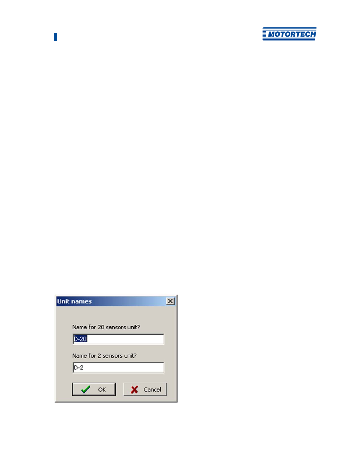
Set the dDevice Name
When the program is first started, the window Unit names opens.
Page 70
8 DenEdit Settings
70 Rev. 02/2019
1. Set the name for your device by changing the entry in the field corresponding to your device
type.
2. Accept the input with OK.
▸ The name is now displayed in the status bar of the software.
Assign the Communication Port
In order to establish communication between the PC and the device, you must first set the
communication port to be assigned to the USB interface.
Proceed as follows:
1. Open the device manager of your PC via the control panel.
2. You can see which COM port was assigned to the USB interface under the entry Ports .
3. Note that only COM ports 1-16 can be set in DenEdit. Change the port assignment if
necessary.
4. Open DenEdit.
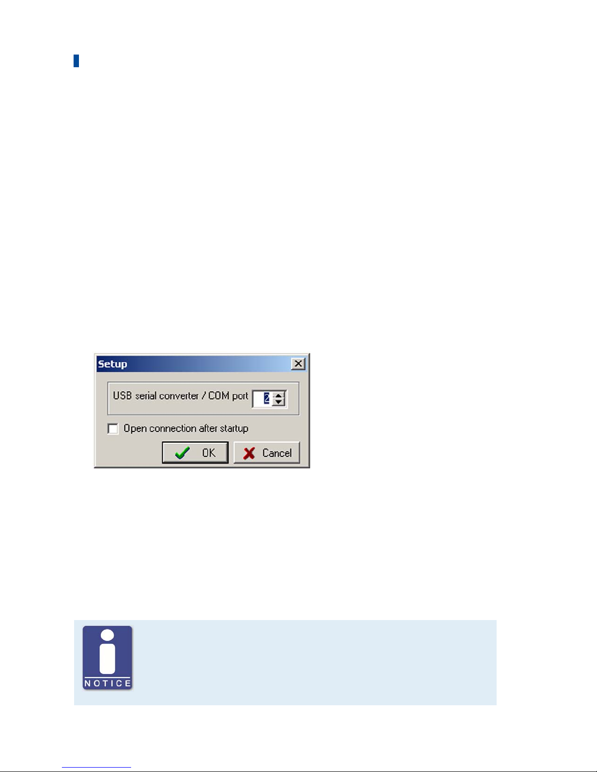
5. Open the window Setup via the menu entry Connection -> Setup.
6. In the field USB serial converter / COM port, enter the number of the COM port set on the PC.
7. If you activate the checkbox Open connection after startup, the software automatically
connects with the connected device after startup if the USB connection is active.
8. Accept the input with OK.
Establish a Connection to the Device and Load the Parameter File
The parameter file of the respective engine must be loaded to the device prior to start-up. The
CD-ROM supplied with the device contains files for engines which have already been calibrated.
If there is no parameter file for the desired engine, a calibration must be performed. This can
only be carried out by MOTORTECH service personnel.
Calibration for diesel and pilot injection engines
For diesel and pilot injection engines, calibration must be performed by
MOTORTECH service personnel.
Page 71

8 DenEdit Settings
Rev. 02/2019 71
Proceed as follows:
1. Connect the device to the PC with the USB cable.
2. Start up DenEdit.
3. Establish a connection between the software and the device via the menu entry Connection -
> Connect USB.
4. Load the parameter file corresponding to your engine via the menu entry Connection -> Open
Parameters.
The file name indicates which file corresponds to which DetCon device type and to which
engine. See also the following example.
Name of the parameter file
The file name of the parameter file indicates the engine associated with the
file. The file extension indicates the DetCon device type for which the file
must be used. For example:
– File: 0824.de2
Engine: MAN E0824E
DetCon: DetCon2
– File: 2842E.den
Engine: MAN E2842E
DetCon: DetCon20
Page 72
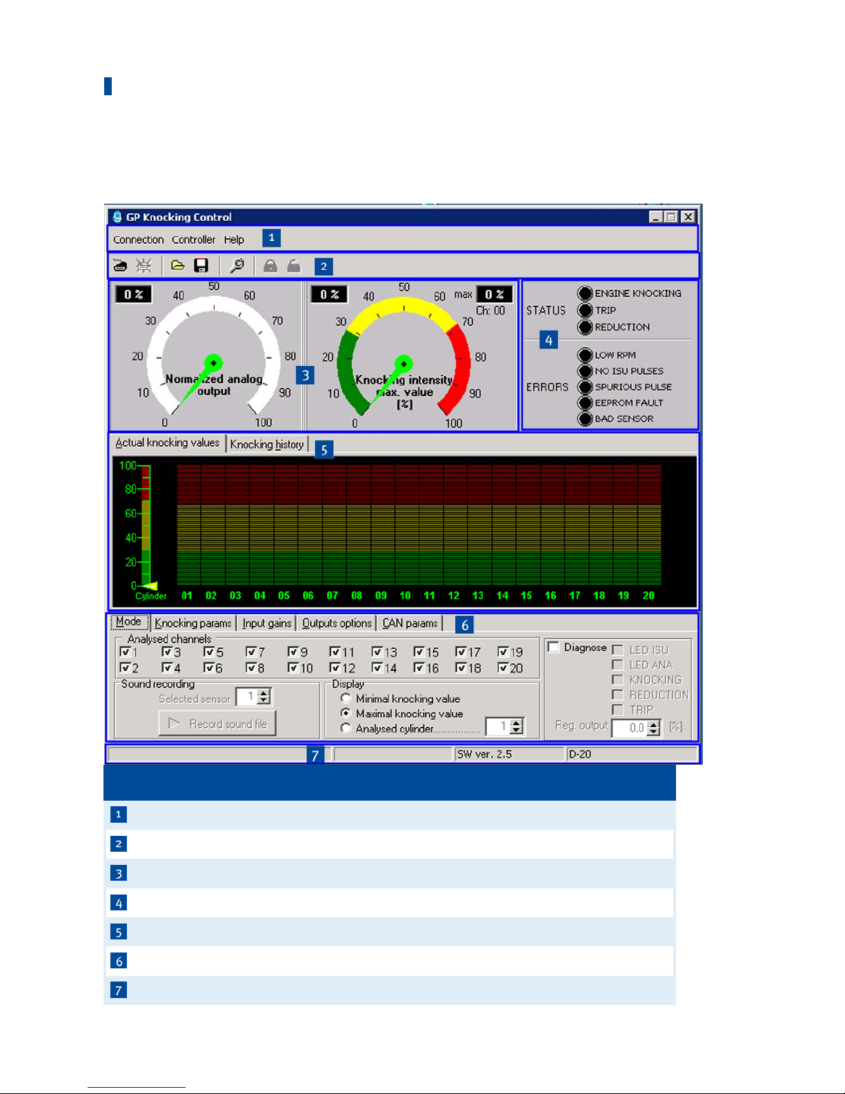
8 DenEdit Settings
72 Rev. 02/2019
8.3 User Interface Overview
The user interface is divided into different areas:
No. Area
Menu bar
Toolbar
Display area of the analog output signal and the knocking intensity
Error and status displays
Tabs for process monitoring
Tabs for the Process Parameters
Status bar
Page 73
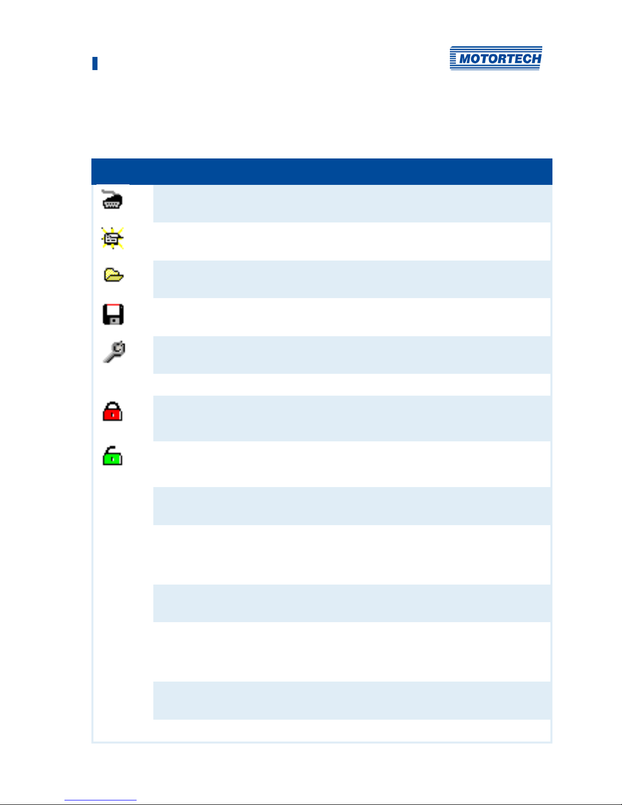
8 DenEdit Settings
Rev. 02/2019 73
8.4 Menu Bar and Toolbar
The following functions are available to you via the symbols on the toolbar and the entries in the
menu bar:
Symbol Menu Function
Connection -> Connect
USB
Establishes connection between DetCon and the PC.
Connection -> Disconnect
Disconnects DetCon from the PC.
Connection -> Open
parameters
Opens a file dialog in which you can select a parameter
file.
Connection -> Save as
Saves the set values as a new parameter file.
Connection -> Setup
Opens a dialog in which the communication port (COM)
settings can be made.
Connection -> Exit
Exits the program.
Controller -> Enter
password
Opens a window for entering a password. The
password is required in order to change parameters.
The default setting of the password is 0 (zero).
Controller -> Deactivate
password
If parameters secured by a password have been
changed, this function can be used to secure password
protection for access to the software.
Controller -> Change
password
Opens a window in which you can change the
password.
Controller -> Get
encrypted password
If you forget your password, you can receive an
encrypted password with this function. Please contact
MOTORTECH service personnel with this password and
the serial number of the device.
Controller -> Two sensors
mode
Switches to two sensors mode in order to operate the
DetCon2.
Controller -> Device SW
ver. ...
Select from the entries displayed the entry
corresponding to the software version of your device
(firmware). The software version used is indicated on
the nameplate on the device.
Controller -> Reset peak
value
Resets the stored peak value of the knocking intensity
displayed on the tab Knocking history.
Help -> About
Opens version and contact information.
Page 74
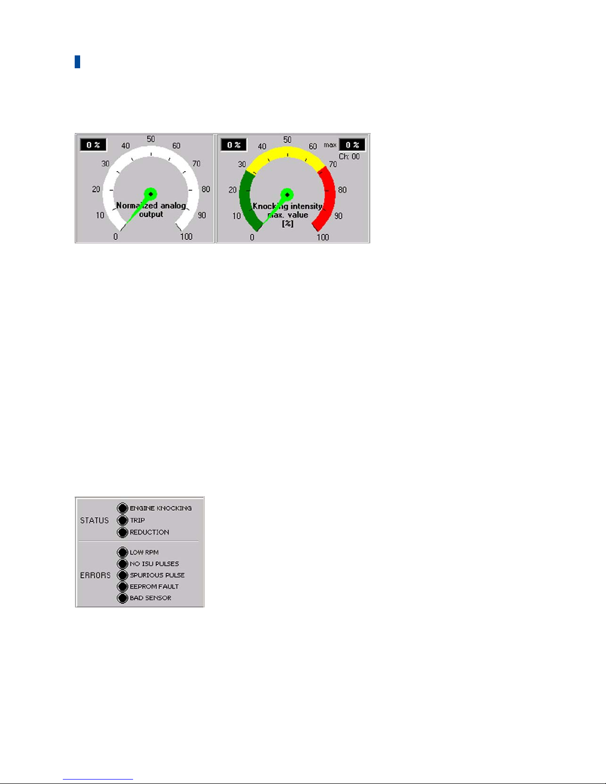
8 DenEdit Settings
74 Rev. 02/2019
8.5 Display Area of the Analog Output Signal and the Knocking Intensity
The output signal of the analog outputs and the knocking intensity are displayed using two
graphic indicating instruments.
Normalized analog output
The left display shows the value of the signal currently present at the analog outputs. The value
is displayed as a percentage of the output range (0-5 V / 4-20 mA). In addition, the displayed
value is indicated numerically on the upper left.
Knocking intensity
Various knocking intensity values can be indicated on the right display. The values are shown as
a percentage of the maximum value. The selection of the displayed value is made in the tab
Mode. Refer to the section Tab: Mode on page 78.
The current minimum and maximum values are also indicated numerically above the display. The
numerical display for the maximum value (upper right) also indicates on which cylinder this
value was measured.
8.6 Error and Status Displays
The status displays indicate the status of the binary outputs and the error displays show errors
which arise during the internal diagnostics check of the control device. The different lights of the
displays indicate the following:
Page 75

8 DenEdit Settings
Rev. 02/2019 75
STATUS
– ENGINE KNOCKING
The selected knocking level Ignition reduction limit has been exceeded in at least one
cylinder. The binary output Engine Knocking is activated.
– TRIP
The knocking level has exceeded the value Immediate stop limit. The binary output Trip is
activated. The engine is shut down if properly wired.
– REDUCTION
The maximum ignition timing reduction via the analog output signals has been exhausted.
The value Maximum output value has been exceeded. The binary output Trip is activated.
With proper wiring, a master control executes a load reduction.
ERRORS
– LOW RPM
This LED indicates that the speed is low and therefore the detonation control unit is not yet
operative.
– NO ISU PULSES
No pulses are detected at the ignition input (Timing). Either the engine has not started or the
ignition sensor unit (ISU) has been wired incorrectly.
– SPURIOUS PULSE
The pulses at the ignition input (Timing) are faulty. This can have the following causes:
defective ignition sensor unit (ISU), incorrect sensitivity of the ignition sensor unit (check
jumper Load Resistance), electrical interference, or noise.
Notice:
With long wire lengths, this LED occasionally flashes as a result of interferences. This does
not indicate an error.
– EEPROM FAULT
The parameters are incorrect as a result of an interference between the PC and the device.
Try to reload the parameters. If this is not successful, the control device must be repaired.
– BAD SENSOR
A faulty detonation sensor has been detected due to inconsistent signals. The display only
lights up if the checkbox Enable bad sensor detect is activated in the tab Output options.
This can have the following causes: the respective detonation sensor is loose, a wire has a
loose connection, or the detonation sensor is not flush against the surface. You can see
which detonation sensor is causing the problem on the tab Actual knocking values. The
number of the failed detonation sensor is displayed in red.
Page 76
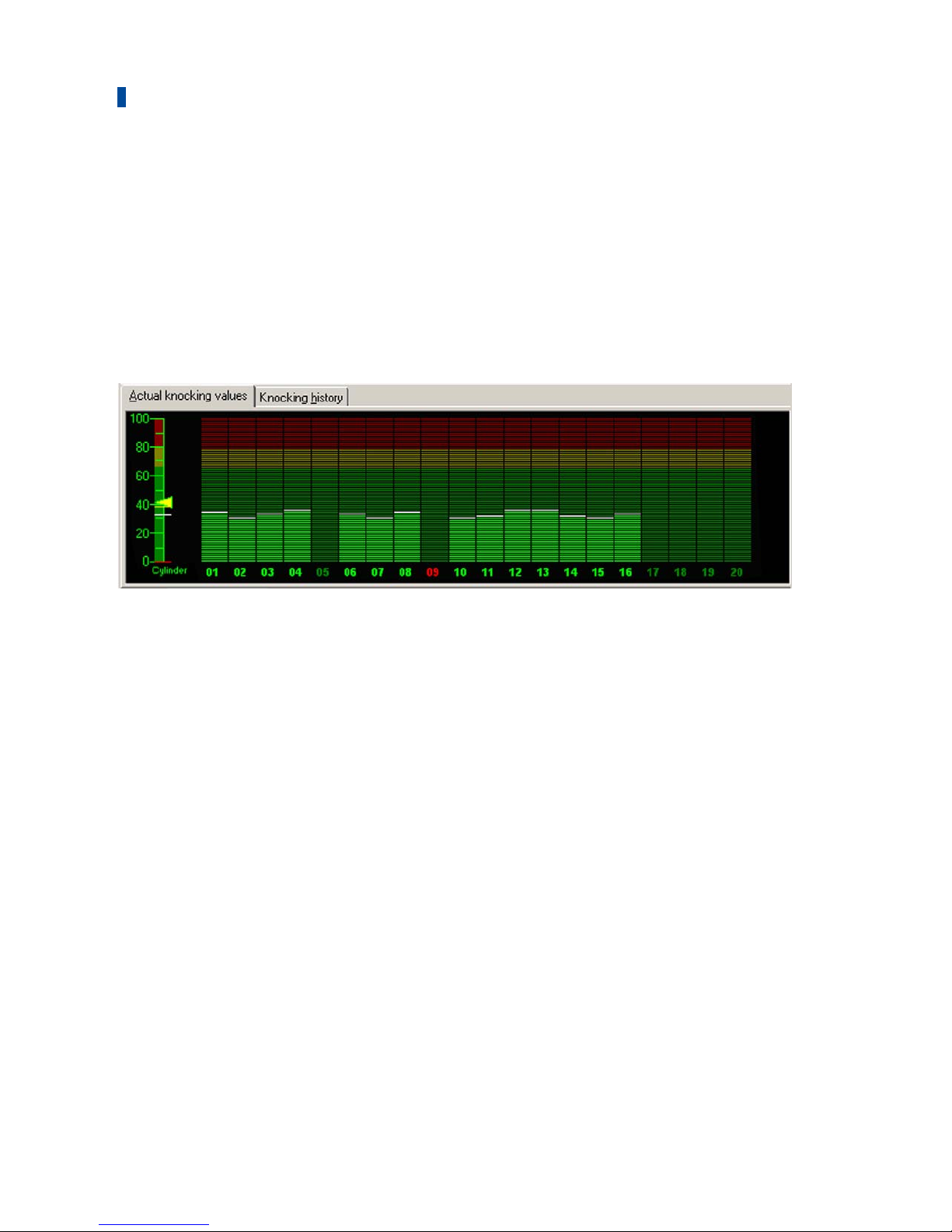
8 DenEdit Settings
76 Rev. 02/2019
8.7 Tabs for Process Monitoring
The following tabs are available for process monitoring:
– Actual knocking values
This tab shows the current knocking intensities detected by all detonation sensors.
– Knocking history
In this tab, you can see the curve of the knocking intensities registered over the last minute.
8.7.1 Tab: Actual Knocking Values
Display Area
In the display area, the current knocking values for every cylinder are shown as bars. The color
background indicates the set limits:
– Ignition reduction limit: the border between green and yellow
– Immediate stop limit: the border between yellow and red
The condition of the detonation sensor is also marked in color. The colors of the sensor number
indicate the following:
– Green: The detonation sensor is active.
– Grayed out: The detonation sensor is not in use.
– Red: The detonation sensor is providing faulty signals or has failed entirely.
Left Column
The scale area on the left additionally indicates the minimum (red line), maximum (yellow line),
and average (white line) knocking values of all cylinders. In addition, the yellow triangle
indicates the highest knocking value detected during the measurement. This value is erased
when the device is switched off or manually via the menu entry Reset peak value.
Page 77
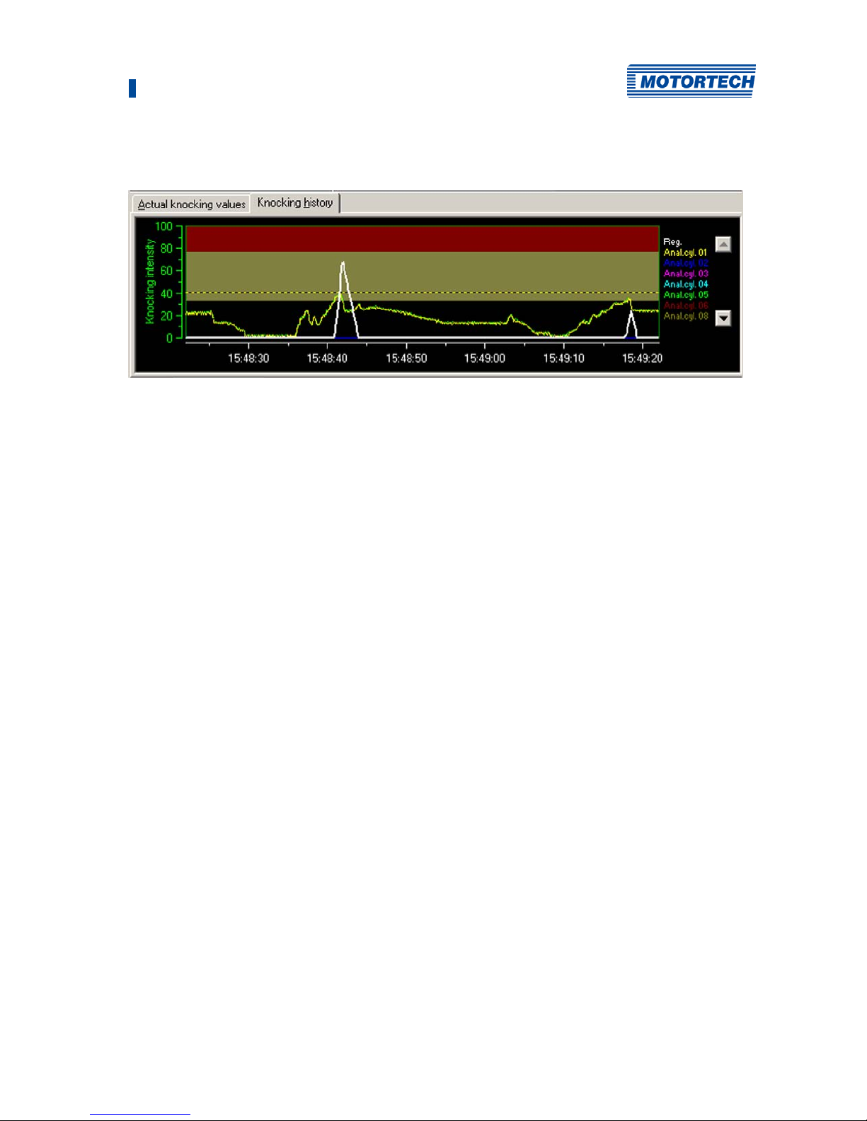
8 DenEdit Settings
Rev. 02/2019 77
8.7.2 Tab: Knocking History
The knocking history continuously shows the curve of the varying knocking intensities
registered over the last minute. The color background indicates the set limits:
– Ignition reduction limit: the border between black and yellow
– Immediate stop limit: the border between yellow and red
The maximum knocking value is shown as a dotted line. The legend on the right indicates which
color corresponds to which cylinder. The white curve (Reg. in the legend) maps the signal of the
analog outputs.
8.8 Tabs for the Process Parameters
The basic settings for the required engine and the device used are set when the parameter file is
loaded. You can inspect and modify these settings as needed in the tabs for the process
parameters.
The following tabs are available for the process settings:
– Mode
In this tab, you can enter general display and diagnostics settings. This is also where you
can start sound recordings of knocking signals.
– Knocking params
This tab shows both engine settings and the parameters for knocking analysis. These
settings are either specified by the parameter file or, if required, determined by MOTORTECH
service personnel during calibration. In order to ensure the correct functioning of the
detonation controller, these values may not be altered.
– Input gains
In this tab, you can amplify or attenuate signals for individual channels in order to
compensate for signals similar to knocking signals.
– Firing sequence
In this tab, you can specify individual firing sequences for special engine types.
– Output options
In this tab, you can enter settings for knocking detection limits and other analysis values.
– CAN params
In this tab, you can enter settings for communication via the CAN bus.
Page 78
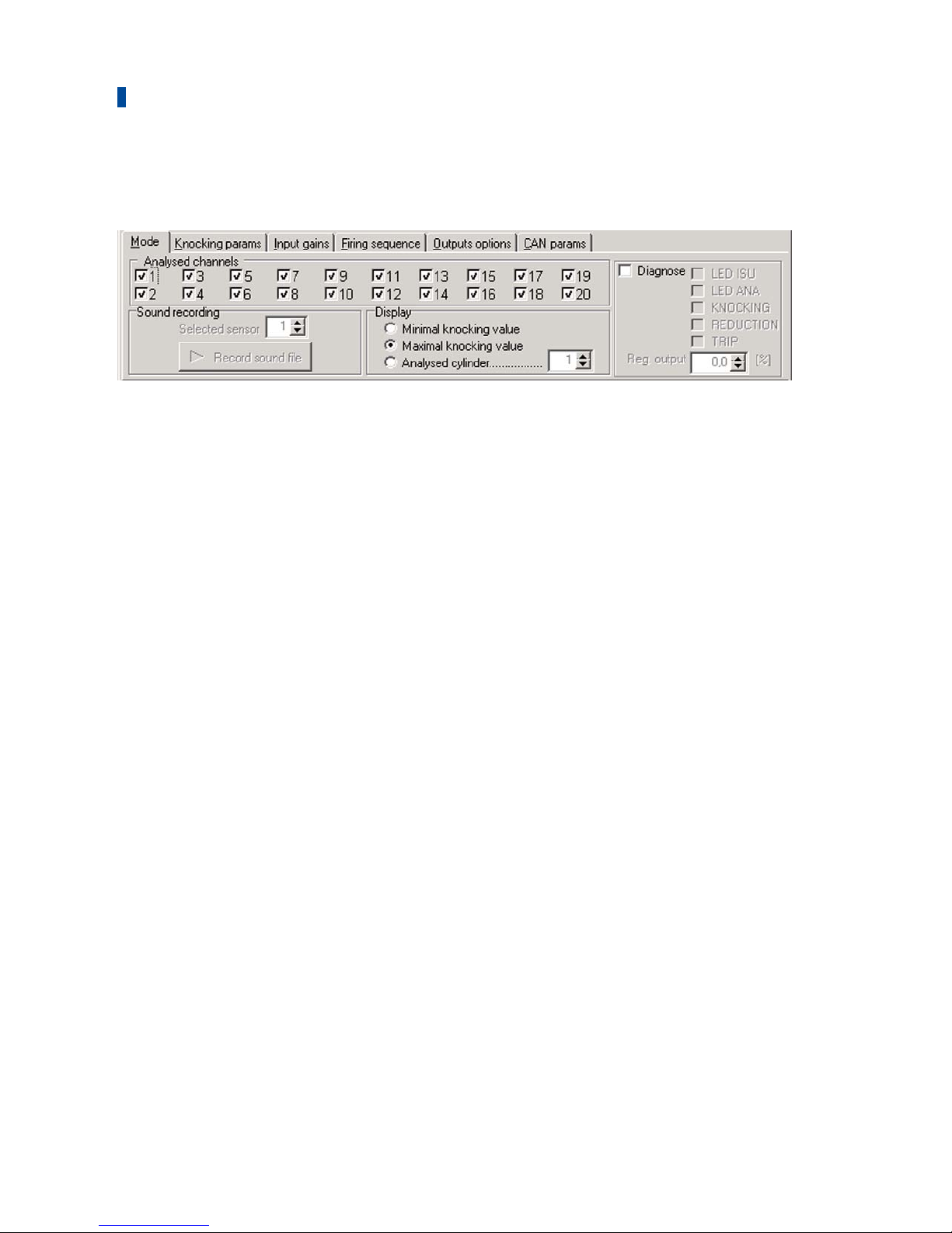
8 DenEdit Settings
78 Rev. 02/2019
8.8.1 Tab: Mode
Analysed channels
Activate the checkboxes of the detonation sensors that you want displayed in the tabs Actual
knocking value and Knocking history. If the display of a sensor is deactivated, the signal of the
detonation sensor still continues to be monitored.
Sound recording
If the device is connected to the running engine, you can make sound recordings of the signal of
a detonation sensor. This is generally executed by MOTORTECH service personnel and should
only be performed upon their request.
Proceed as follows:
1. Set the desired detonation sensor in the field Selected sensor.
2. Then click on the button Record sound file.
▸ An input window opens.
3. Select a save location for the sound file (*.au) and enter a filename.
▸ The sound recording starts and is shown graphically in a separate window.
4. Click on Stop to stop the recording.
Display
You can select which value is displayed in the knocking intensity pointer instrument via the
following settings:
– Minimal knocking value
The sensor with the lowest knocking intensity is automatically selected and displayed.
– Maximal knocking value
The sensor with the highest knocking intensity is automatically selected and displayed.
– Analysed cylinder
You can specify the cylinder whose knocking intensity should be displayed. The number
entered corresponds to the position of the desired cylinder in the firing order (e.g. 2 for the
second cylinder in the firing order).
Page 79
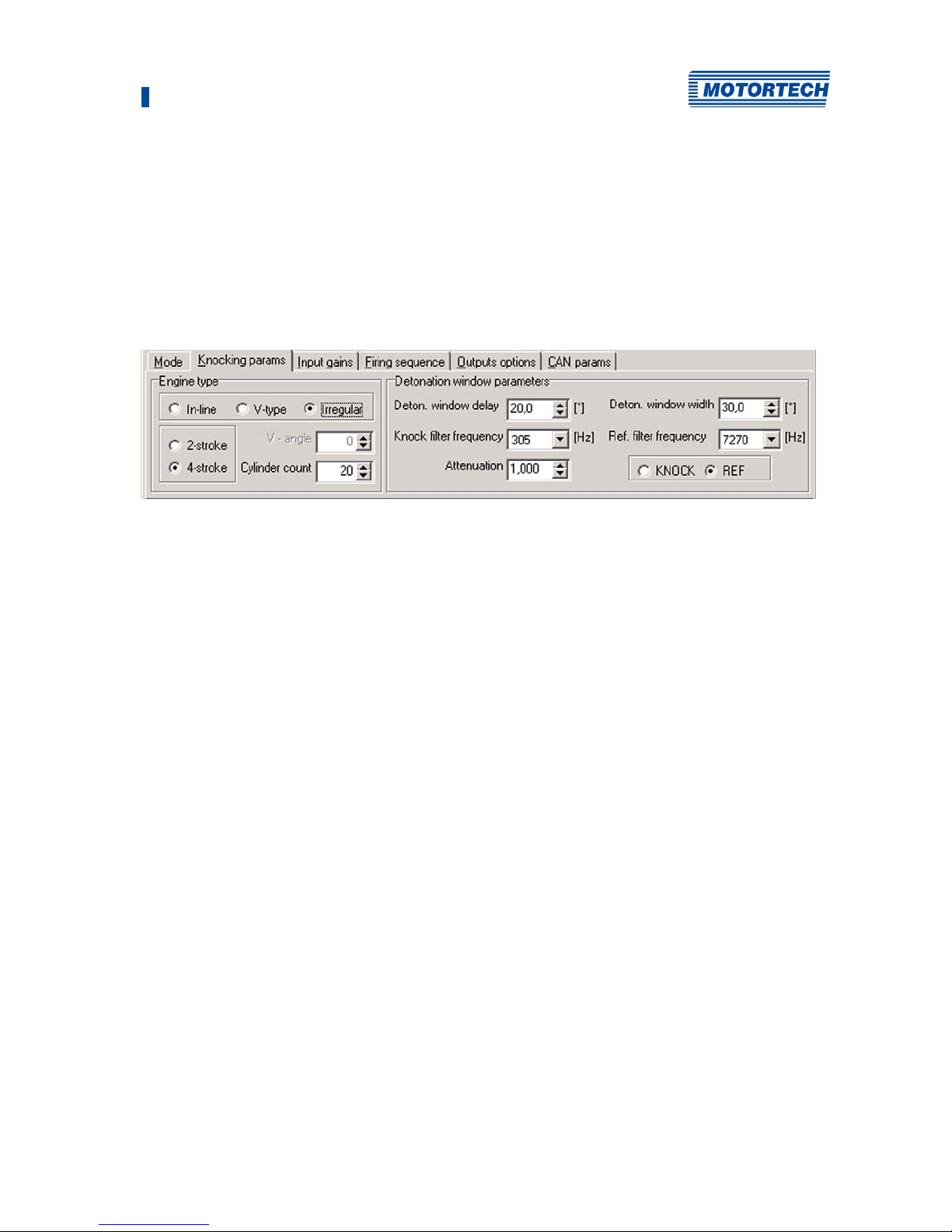
8 DenEdit Settings
Rev. 02/2019 79
Diagnosis
The binary and analog outputs can be tested via the settings in this area. Activate the checkbox
to activate the respective output. You can simulate an analog output signal via the field Reg.
Output in order to test the connection to an ignition controller, for example. The checkbox
Diagnostics must be deactivated again for operations.
8.8.2 Tab: Knocking Params
Engine type
In this area, you can select the engine settings suited to your application. In general, these
values are contained in the parameter file and must not be manually adjusted:
– In-line, V-type, Irregular
Select the engine type. Select In-line for an in-line engine and V-type for a V engine. The
setting Irregular allows you to define an individual firing sequence in the tab Firing
sequence.
– 2-, 4-stroke
Select the operating mode of the engine: 2-stroke or 4-stroke.
– V-angle
Enter the firing angle for V engines.
– Cylinder count
Enter the number of cylinders.
Detonation window parameters
In this area, the values are entered for the frequency range in which knocking is likely to occur.
These settings are either specified by the parameter file or, if required, determined by
MOTORTECH service personnel during calibration. In order to ensure the correct functioning of
the detonation controller, these values may not be altered.
– Deton. window delay
Delay of the first cylinder ignition measured by the interval following the ignition pulse. The
basis is the rising edge of the synchronization pulse.
– Deton. window width
Window of time for knock analysis.
– Knock filter frequency
Characteristic knocking frequency.
Page 80
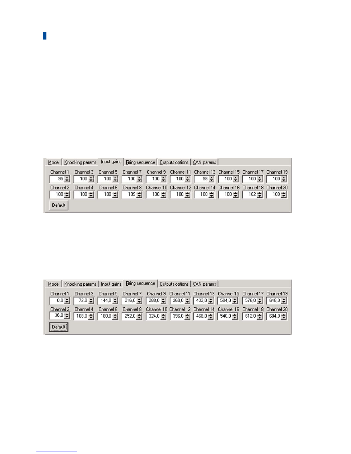
8 DenEdit Settings
80 Rev. 02/2019
– Ref. filter frequency
Normal frequency of the engine without knocking.
– Attenuation
Balance between the reference signal (background noises and normal engine vibration) and
the knocking signal.
– KNOCK, REF
Selection of whether the knocking signal (in %) or the reference signal (in %) should be
shown on the knocking intensity display.
8.8.3 Tab: Input Gains
This tab is only available to you if the selected device software is version 2.0 (firmware, see
status line) or higher (menu Controller). The settings in this tab allow you either to amplify the
input signals of the individual detonation sensors or to attenuate them (values <100) in order to
suppress signals similar to knocking signals. Values between 0 and 300 can be specified. The
default setting is 100. This value can be restored via the button Default .
8.8.4 Tab: Firing Sequence
This tab is only available to you if you have selected the device software version 2.0 (firmware,
see status line) or higher (menuController) and selected the setting Irregular as Engine type in
the tab Knocking Params. You have the option of entering a freely definable firing sequence. Via
the button Default, settings are set to conform to an in-line engine. This basic setting can be a
good starting point for entering your individual deviations.
Page 81
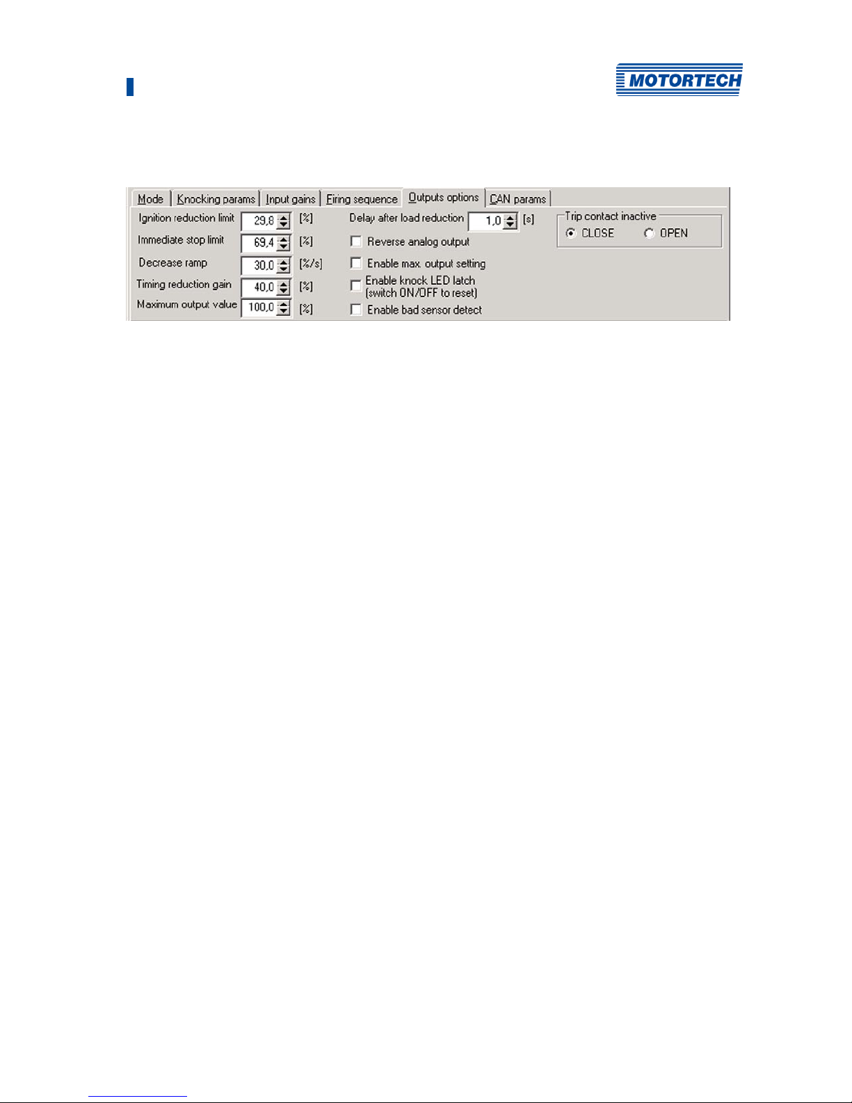
8 DenEdit Settings
Rev. 02/2019 81
8.8.5 Tab: Output Options
Settings made in this tab influence the signals of the analog and binary outputs. Please refer to
the section Functional Description on page 13 for more information on the limits you can set
here.
Ignition reduction limit
Enter the limiting value beyond which the engine is considered to be knocking. If the value is
exceeded, the binary output ENGINE KNOCKING is activated and the values assigned to the
timing reduction are altered.
Immediate stop limit
Enter the limiting value beyond which the binary output TRIP is activated. This causes the engine
to shut down if properly wired.
Decrease ramp
Enter the value for the Decrease ramp. The value specifies the rate at which the timing reduction
signal (analog outputs) is disabled as soon as knocking decreases below the Ignition reduction
limit.
Timing reduction gain
Enter the value for the Timing reduction gain. This value influences the rate at which the timing
reduction signal (analog outputs) is amplified when knocking is detected. This rate equals the
mathematical product of the set value and the knocking intensity.
Maximum output value
Enter the value which the timing reduction signal (analog outputs) should be limited to. This
setting only takes effect if the checkbox Enable max. output setting is activated.
Delay after load reduction
Enter the delay with which the timing reduction signal is to be reduced when the knocking value
falls again below the Ignition reduction limit due to a load reduction.
Reverse analog output
Activate the checkbox to reverse the signal of the analog outputs. A maximum level then
indicates no knocking and vice versa.
Page 82
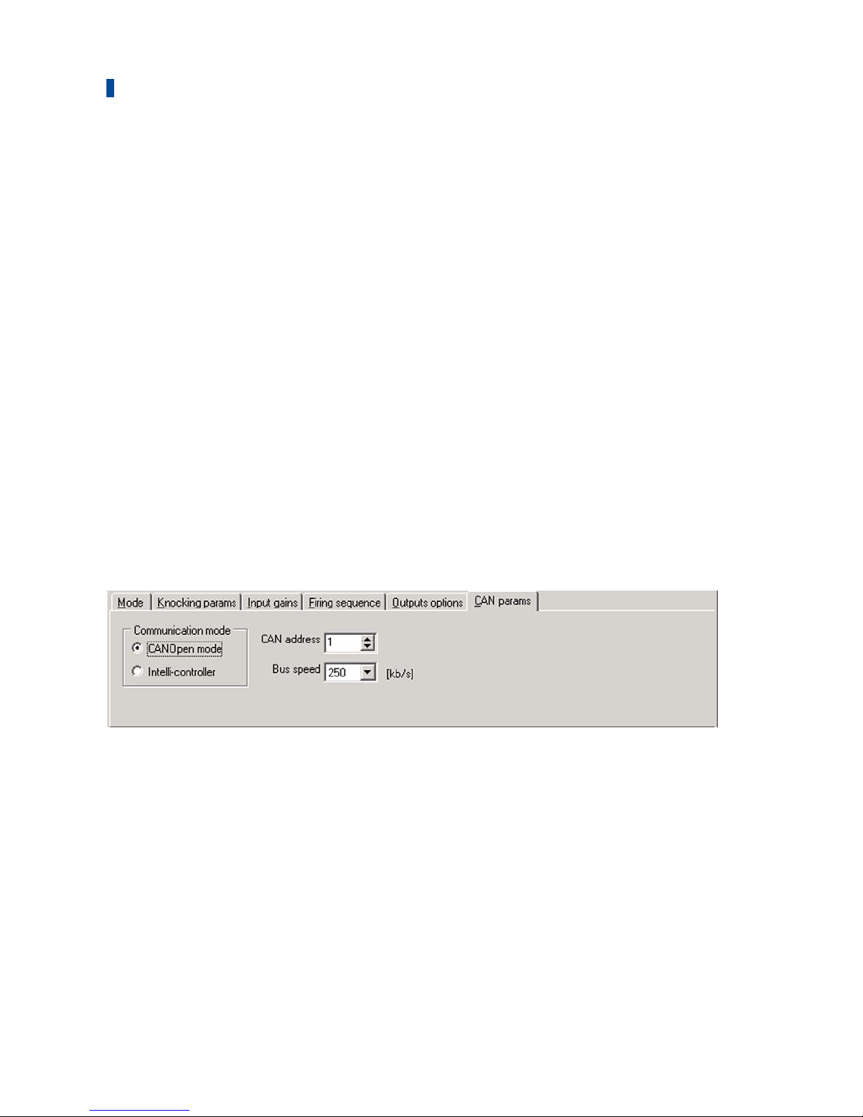
8 DenEdit Settings
82 Rev. 02/2019
Enable max. output setting
Activate the checkbox to limit the signal of the analog outputs to the value in the field Maximum
output value.
Enable knock LED latch (switch ON/OFF to reset)
Activate the checkbox so that the status display ENGINE KNOCKING remains lit when knocking is
detected which falls below the Ignition reduction limit. With this setting, the cylinder which
triggered the knocking can still be identified after the engine is shut off. In order to delete the
status display, deactivate the checkbox and activate it again.
Enable bad sensor detect
Activate the checkbox so that defective detonation sensors are indicated via the status display
BAD SENSOR. This function only detects sensors which provide faulty signals. If a wire has
ruptured or a sensor gives no signals for some other reason, it is not indicated on this display. If
a defective sensor is detected, the binary output TRIP is also activated.
Trip contact inactive (CLOSE, OPEN)
Using this setting, you can specify whether the binary output TRIP is open during normal
operation and closed when the Immediate Stop Limit is exceeded (setting: OPEN) or vice versa
(setting: CLOSE).
8.8.6 Tab: CAN Params
Communication mode
Depending on the device connected, select the mode CANOpen mode or Intelli-controller.
CAN address
Enter the CAN address with which the device will be identified in the CAN bus.
Bus speed
Enter the transmission speed that was set for the CAN bus.
Page 83
8 DenEdit Settings
Rev. 02/2019 83
Communication with ALL-IN-ONE
Select the following settings for communication with the ALL-IN-ONE gas
engine controller:
– Select Intelli-controller
– CAN address: 79
– Bus speed: 250 kBit/s
Communication with PowerView3
Select the following settings for communication with the HMI module
PowerView3:
– selectCANopen mode
– CAN address: freely selectable (set identical address in PowerView3)
– Bus speed: 250 kBit/s
8.9 Status Bar
The status bar shows the connection status (offline/connected), the selected device software
version (firmware), and the assigned device name. If you move the cursor over the user interface,
short help texts about the tabs, symbols, and menu entries appear in the status bar.
Page 84

84 Rev. 02/2019
9.1 Start-up
Before you start up the DetCon detonation controller, take note of the following:
– Has the parameter file corresponding to the engine and the DetCon device type been loaded
to the device?
– Have the detonation sensors been wired in accordance with the firing order of the engine?
– Has the ignition sensor unit (ISU) or the camshaft sensor been wired correctly?
9.2 Start-up of the ATEX enclosure
The following points must be checked before initial operation:
– The enclosures must be properly installed.
– The enclosures must not be damaged, especially the gaskets.
– There must be no foreign objects in the housing.
– The terminal compartment must be clean.
– The mounting and equipment screws must be firmly tightened.
– The cable bushings must be firmly tightened.
– All cables must be installed in the bushings according to the degree of protection.
– Unused holes must be sealed with certified plugs.
The external protective conductor connection must be installed correctly and close to the
housing.
9.3 Shutdown
The device is shut down by disconnecting it from the power supply.
9 Operation
Page 85

85 Rev. 02/2019
Detonation Sensor Errors
If the checkbox Enable bad sensor detect is activated in the tab Output Options, defective
detonation sensors are indicated via the status display BAD SENSOR. This function only detects
sensors which provide faulty signals. If a wire has ruptured or a sensor gives no signals for some
other reason, it is not indicated on this display. If a defective sensor is detected, the binary
output TRIP is also activated.
10 Disturbances
Page 86

86 Rev. 02/2019
Test the functioning of the system each time the engine is inspected. In particular, follow the
following steps:
– Check the functioning of the analog outputs.
– Check the functioning of the digital outputs.
– Ensure that the sensors and wires are firmly connected.
11.1 Repair and Maintenance Work on the ATEX Enclosure
– Repair and maintenance work on the ATEX enclosure may only be carried out by authorized
and appropriately trained personnel.
– Maintenance and repair must be carried out in accordance with EN 60079-17.
– During maintenance, in particular the parts on which the protection class depends must be
checked. This includes in particular the seals and the sealing system as well as lead
bushings.
– The maintenance intervals must be selected depending on the operating conditions and the
operating time.
– When operating the ATEX enclosure, the applicable national regulations of the country of
use must be observed.
11.2 Spare Parts and Accessories
For spare parts and accessories, please refer to our current Product Guide, which is available for
you to download on the internet at www.motortech.de.
11 Maintenance
Page 87

87 Rev. 02/2019
0
0-5 V output
Data .......................................................... 31
Display ..................................................... 74
Wiring ....................................................... 65
4
4-20 mA output
Data .......................................................... 31
Display ..................................................... 74
Wiring ....................................................... 65
A
Abbreviation ................................................... 7
ASO Output
Use ........................................................... 17
Wiring ....................................................... 58
Auxiliary Synchronization Output
Use ........................................................... 17
Wiring ....................................................... 58
B
Binary outputs
Data .......................................................... 31
Wiring ....................................................... 64
C
Camshaft sensor
Installation ................................................ 56
Use ........................................................... 17
Wiring ....................................................... 62
CAN bus
Interface ................................................... 32
Setting ...................................................... 82
Communication
With PC ..................................................... 69
Communication port ...................................... 69
Connections
Overview ................................................... 35
D
Declaration of Conformity .............................. 20
Decrease ramp
Declaration ............................................... 13
Setting ...................................................... 81
Delay after load reduction
Declaration ............................................... 13
Setting ...................................................... 81
Device
Connecting with PC .................................... 69
Disposal .................................................... 12
Function .................................................... 13
Dimensions
Drawing .................................................... 35
Overview ................................................... 28
E
Engine
Calibrating ................................................ 79
Engine knocking
Declaration ................................................ 13
Engine Stop
Declaration ........................................... 13, 67
Engine type
Setting ...................................................... 79
Error
Display ...................................................... 74
F
Firing sequence
Setting ..................................................... 80
Function
Overview ................................................... 13
H
History
Knocking intensity ..................................... 77
I
Ignition controller
Wiring ....................................................... 58
Ignition pulse input
Data .......................................................... 31
Ignition reduction limit
Declaration ................................................ 13
Setting ...................................................... 81
Ignition sensor unit
Data .......................................................... 34
Installation ................................................ 54
Use ........................................................... 17
Wiring ...................................................... 60
Immediate stop limit
Declaration ................................................ 13
Setting ...................................................... 81
Input signal
Amplifying ................................................ 8 0
Inputs
Overview ................................................... 31
ISU
Data .......................................................... 34
Installation ................................................ 54
Use ........................................................... 17
Wiring ...................................................... 60
J
Jumper
Position ..................................................... 35
Use ........................................................... 17
12 Index
Page 88

12 Index
88 Rev. 02/2019
K
Knocking frequency
Setting ..................................................... 79
Knocking intensity
Display ................................................ 74, 76
History.......................................................77
Detonation sensor
Activate .................................................... 78
Data ......................................................... 32
Wiring ...................................................... 57
Detonation sensor input
Data .......................................................... 31
Knocking signal
Amplifying ................................................ 80
Recording ................................................. 78
L
Limits
Setting ..................................................... 81
Load Reduction
Declaration .......................................... 13, 67
Load Resistance Jumper
Position .................................................... 35
Use............................................................ 17
M
Menu
Software ................................................... 73
MIC3
Wiring ...................................................... 58
MIC4
Wiring ...................................................... 58
MIC5
Wiring ...................................................... 58
MIC850
Wiring ...................................................... 58
Mode ............................................................ 78
O
Outputs
Overview ................................................... 31
Testing ..................................................... 78
P
Parameter file
Loading .................................................... 69
Power consumption ........................................ 31
R
Regulations
Overview .................................................. 20
S
Safety Instructions
Device ....................................................... 11
General ....................................................... 9
Software
Installation ............................................... 69
Menu ........................................................ 73
Overview ................................................... 72
Symbols ................................................... 73
System Requirements ................................ 68
Sound recording ............................................ 78
Start-up ........................................................ 84
Status
Display ..................................................... 74
Supply voltage
Device ...................................................... 31
Symbols
Software ................................................... 73
T
Temperature ................................................. 28
Timing Correction
Declaration .......................................... 13, 67
Timing reduction gain
Declaration ............................................... 13
Setting ...................................................... 81
Trip
Declaration ............................................... 13
Setting ...................................................... 81
U
USB
Interface ................................................... 32
W
Weight .......................................................... 28
Wiring
0-5 V output .............................................. 65
4-20 mA output ......................................... 65
Camshaft sensor ......................................... 62
Ignition sensor unit ................................... 60
Detonation sensor ........................................ 57
Page 89

Page 90

 Loading...