

MOTORSCAN MEMOBIKE 6050 Operating Instructions Manual

1
OPERATING INSTRUCTIONS
TECH SUPPORT
HOTLINE
+1 (888) 665-8804 x1
support@svd.tools
OPERATING INSTRUCTIONS
MS6050EN
Mod. 6050_EN
First Edition
February 2014
A.Cavalca
Release 01
February 2016
A.Cavalca
Release 02
March 2016
A.Cavalca
Any printed or digital reproduction of this manual is forbidden without the authorization of
the copyright holder.
Printing the digital version of this manual is permitted only for the purpose of producing a
back-up copy for the user of the product.
The features and data described in this manual are not binding on the manufacturer. The
right is reserved to make changes or modifications without prior notice or product
replacement.
Product and business names appearing in this manual may or may not be registered
trademarks and are used for identification purposes only. All trademarks are the property
of their respective owners.

MS6050EN
OPERATING INSTRUCTIONS
Dear Customer,
This product is part of the MOTORSCAN® family of products. It is the result of many
years of research and development.
The EOS S.r.l. Motorscan® Division is glad to have you as a customer.
Please contact one of our authorized distributors or our customer service department
for any technical questions.

OPERATING INSTRUCTIONS
MS6050EN
Blank Page

MS6050EN
OPERATING INSTRUCTIONS
INDEX I
INDEX
INDEX ........................................................................................................................................... i
INTRODUCTION ................................................................................................................. 1
INSTALLATION ................................................................................................................... 4
OPERATING INFORMATION ............................................................................................. 4
SYMBOLS ........................................................................................................................... 6
1.0.0 - PRODUCT DESCRIPTION ...................................................................................... 7
1.1.0 - GENERAL ................................................................................................................ 7
1.2.0 - SPECIFICATIONS ................................................................................................... 7
1.3.0 - FRONT / CONNECTIONS VIEW ............................................................................. 8
1.4.0 - KEYBOARD VIEW ................................................................................................... 8
1.5.0 - STANDARD ACCESSORIES ................................................................................. 10
1.6.0 - OPTIONAL ............................................................................................................. 12
2.0.0 - CONNECTING ....................................................................................................... 22
2.1.0 - POWERING THE TOOL......................................................................................... 23
2.2.0 - MOTORCYCLE IDENTIFICATION ......................................................................... 23
2.3.0 - CONNECTING TO THE MOTORCYCLE USING A MASTER/SLAVE CABLE ...... 26
2.4.0 - CONNECTING TO THE MOTORCYCLE USING THE “UNIVERSAL” CABLE ...... 27
2.5.0 - CONNECTING TO THE MOTORCYCLE USING BMW SLAVE CABLE ................ 28
3.0.0 - OPERATION .......................................................................................................... 29
3.1.0 - SETUP MENU ........................................................................................................ 30
3.2.0 - SETTING MENU .................................................................................................... 32
3.2.1 - SCREENSHOT MANAGEMENT ............................................................................ 37
3.2.2 - REPORT ................................................................................................................ 38
3.3.0 - BATTERY INFORMATION SCREEN ..................................................................... 41
3.4.0 - DTC GLOBAL SEARCH ......................................................................................... 45
3.4.1 - DATA LOGGER ..................................................................................................... 48
3.5.0 - SELECTING THE SEARCH MODE FOR SYSTEMS INSTALLED ........................ 53
3.5.1 - MANUAL SEARCH ................................................................................................ 53
3.5.2 - MANUAL SEARCH BY VEHICLE SELECTION ..................................................... 54
3.5.3 - MANUAL SEARCH BY ECU SELECTION ............................................................. 58
3.5.4 - AUTOMATIC SEARCH CONNECTION ................................................................. 61
3.6.0 - ECU MENU ............................................................................................................ 63
3.6.1 - ECU DATA ............................................................................................................. 64
3.6.2 - PARAMETERS ....................................................................................................... 64
3.6.3 - READING STORED FAULTS ................................................................................ 65
3.6.4 - ERASING STORED FAULTS ................................................................................. 67
3.6.5 - DIAGNOSTIC PROCEDURES ................................................................ ............... 68
3.6.6 - CONFIGURATIONS ............................................................................................... 69
4.0.0 - APPENDIX ............................................................................................................. 71
4.1.0 - SCREEN ................................................................................................................ 71
4.1.1 - “START-UP” SCREEN ........................................................................................... 71
4.1.2 - “MENU” SCREEN .................................................................................................. 72
4.1.3 - “PROCEED - EXIT” SCREEN ................................................................................ 73
4.1.4 - “BINARY SELECTION” SCREEN .......................................................................... 73

OPERATING INSTRUCTIONS
MS6050EN
II INDEX
4.1.5 - “MESSAGE” SCREEN ........................................................................................... 74
4.1.6 - “MULTIPLE SELECTION” SCREEN ................................................................ ...... 74
4.1.7 - “PARAMETERS TABLE” SCREEN ........................................................................ 75
4.2.0 - TYPES OF DIAGNOSTICS .................................................................................... 76
4.2.1 - SERIAL COMMUNICATION................................................................................... 76
4.2.2 - BLINKING CODES ................................................................................................. 76
4.2.3 - DISPLAY CODES .................................................................................................. 77
4.2.4 - MANUAL PROCEDURE......................................................................................... 77

MS6050EN
MOD:6050
OPERATING INSTRUCTIONS 1
INTRODUCTION
This manual is an integral part of the product. Read these instructions carefully before using
the tool and keep them in a safe place. EOS S.r.l. Motorscan® Division apologizes for any
errors in the text.
Brand names and products mentioned in the document are registered brands of the relevant
owners.
EOS S.r.l. Motorscan® Division is not responsible to third parties for specific, collateral,
accidental, direct, or indirect damage related to, or deriving from the product purchase and use.
Copies of this document and technical information are available from an authorized distributor of
EOS S.r.l. Motorscan® Division.
This document may not be copied or distributed, in part or its entirety, in any form or by any
means, without prior written authorisation from EOS S.r.l. Motorscan® Division.
EOS S.r.l.
Motorscan® Division
Via Monte Aquila, 2 Corcagnano
43124 PARMA – Italy
Tel. +39 0521 631411
www.motorscan.com
sales@motorscan.com
support@motorscan.com
MOD: 6050
MS6050EN
2 OPERATING INSTRUCTIONS
IMPORTANT INFORMATION ABOUT PERSONAL SAFETY
GENERAL SAFETY IN THE WORKSHOP.
DANGER OF SUFFOCATION
GASOLINE ENGINES
Exhaust gases from gasoline vehicles contain Carbon Monoxide, a colorless and odorless
gas which, in case of inhalation, can cause serious physical injury or death. When working
under a vehicle, be very careful. Some components of exhaust gases are heavier than air.
Be careful also when working on LPG-propelled vehicles.
DIESEL ENGINES
The exhaust gas from a diesel engine has a composition that varies according to: type of
engine, of induction, conditions of use, and fuel composition. The diesel exhaust includes
gas (CO, CO2, NO and HC) and particles (soot, sulphates and PAHs). The small carbon
particles forming soot remain suspended in the air and can be breathed in. Small amounts
of toxic components are also present.
SAFETY MEASURES:
Always ensure good ventilation and breathing protection (especially when working under a
vehicle. Always operate the exhaust fan system when working in confined spaces.
DANGER OF CRUSHING
Ensure that the vehicle is locked in place to prevent possible crushing.
SAFETY MEASURES:
Make sure that the vehicle is unable to move by engaging the hand brake and locking the
wheels.
DANGER OF INJURY
Whether engines are at a standstill or operating, there are moving parts (belts, etc.) that can
injure hands and arms. Pay particular attention to electrically operated fans since these may
unexpectedly start up even when the engine itself is off.
SAFETY MEASURES:
Never place hands near moving parts when the engine is on. When working near electrically
operated fans, let the engine cool first and then unplug the fan.
Keep the test instrument connection wires as far as possible away from moving parts of the
engine.
MS6050EN
MOD:6050
OPERATING INSTRUCTIONS 3
DANGER OF BURNS
Some of the components in engines (exhaust gas manifold, etc.) can become very hot, as can
certain sensors. Remember to never touch these parts.
SAFETY MEASURES:
Wear protective gloves. Never allow the test instrument connection wires to rest on or near hot
parts. Never keep the engine running after the tests.
DANGER OF FIRE OR EXPLOSION
When work is being carried out on the fuel system (fuel pump, injectors and carburetor, etc.)
there may be a risk of fire or explosion owing to the fuels used and/or the vapors that these
products form.
SAFETY MEASURES:
Disconnect the ignition system. Allow the engine to cool.
Do not use open flames or anything liable to produce sparks.
Do not smoke.
Collect any spilled fuel.
Operate exhaust fans in closed rooms.
SOUND LEVEL
When working near a vehicle, especially at high engine speed, noise levels can reach 90dB.
Long term exposure to such noise sources can cause hearing damage.
SAFETY MEASURES:
Wear hearing protection.
DANGEROUS VOLTAGE
Work safely on vehicle electrical systems. Do not touch electrically “live” parts of engines. Be
aware of the risk of shock from damaged connections.
SAFETY MEASURES:
Only use the cables supplied with the test instrument. Make sure that the insulation is not
damaged.
Do not touch live parts of the vehicle when testing with the engine running.
Only make test connections with suitable systems (test cables, specific adapter cables).
MOD: 6050
MS6050EN
4 OPERATING INSTRUCTIONS
DANGER OF ASFIXIATION
If subjected to high temperatures (over 250 °C or owing to fire outbreaks), exhaust gas hoses
may release highly toxic gases.
SAFETY MEASURES:
Immediately contact a physician if such gas is inhaled.
Use neoprene or PVC gloves to eliminate combustion residuals.
Fire residuals can be neutralized with a calcium hydroxide solution. This forms calcium fluoride
which can be removed with water.
DANGER OF CORROSION
Acids can harm the skin if not protected.
The residual condensate in gas sampling hoses and the condensate separator unit contains
acids.
Take great care when replacing the oxygen sensor (O2) and the nitric oxide sensor (NO). They
contain highly corrosive substances.
Corrosive liquid may be spilled if a liquid crystal indicator is broken. This liquid should never be
touched, inhaled or swallowed.
SAFETY MEASURES:
In case of contact with the skin, immediately wash the affected area with water and contact a
physician.
Immediately contact a physician if such products are inhaled or swallowed.
GENERAL INFORMATION
INSTALLATION
Never allow the instrument to be exposed to the sun for long periods of time or to allow it to
stand near hot equipment (stoves, heaters, etc.): the maximum operating temperature is 40
°C/105 F.
Do not move the instrument from a hot place to a cold place and vice versa. The formation of
condensation inside the device may damage the electronic circuits.
Protect the instrument from rain or from excessive moisture.
OPERATING INFORMATION
To prevent contamination from toxic gas, it is advisable to use the instrument in a sufficiently
ventilated place or to channel exhaust gases outdoors.
Never pull on the instrument’s cables.
All connections should be made when the vehicle engine in question is off.
Check that all cables are far away from hot parts (over 50 °C/130F) or moving parts.
Disconnect all engine connections before moving the vehicle in question.

MS6050EN
MOD:6050
OPERATING INSTRUCTIONS 5
CLEANING
When necessary, the outer surfaces of the instrument should be cleaned: never use cleaning
products containing spirits, ammonia or gasoline. Only use neutral detergents and a soft,
slightly moistened cloth.
IMPORTANT INFORMATION ABOUT PRODUCT SAFETY
This MOTORSCAN® product provides a high level of protection against the risk of electric
shock.
The installer is responsible for connecting it to a correctly grounded electrical socket. Seek
technical assistance before using an adapter or extension cable. These devices could interfere
with the grounding circuit.
Connection of the appliance to an incorrectly wired electrical outlet could result in electrocution.
Comply with the following rules to protect against the risk of electrocution:
Only connect the instrument to electrical sockets delivering the correct voltage. Contact the
electric utility if you are uncertain as to the outlet voltage.
If the instrument has other wires besides the power cable, these must be connected to their
respective connectors before connecting the power cables to the electrical outlet. Disconnect
the power cables from the sockets before removing other wires.
Strictly comply with the following instructions when servicing:
Always replace fuses with others of equal value (see indications on the label or in this manual).
NEVER open the cover of the instrument: you could risk electrocution. This operation may only
be carried out by a qualified technician and not before having disconnected the power supply
cable.
Deviating from the instructions in this manual or attempting to repair the instrument carries the
risk of electric shock.
Pressing too hard on the display may damage the instrument.
Please contact a service technician if the instrument fails to correctly function after following the
operating instructions.
Check that all installed spare parts have technical characteristics identical to those of the
original parts. Other parts may not possess the same safety characteristics.
Always contact qualified technical personnel if repairs are required.

MOD: 6050
MS6050EN
6 OPERATING INSTRUCTIONS
SYMBOLS
Symbols used in the DEVICE:
ALTERNATING CURRENT
GROUND PROTECTION
CONSULT THE INSTRUCTION MANUAL
RISK OF BURNS
RISK OF ELECTROCUTION
NEVER ATTEMPT TO REMOVE THE COVER
(operation only to be carried out by qualified
technicians)
CE CONFORMITY MARK
It indicates compliance with the relevant European Union
Directives.
Entry to the National Registry of
Manufacturers of Electrical and
Electronic Equipment
n ° IT14010000008257
INFORMATION FOR THE USERS
Pursuant to art.13 of the Law Decree 25 July 2005, n.151
“Implementation of directives 2002/95/CE, 2002/96/CE and
2003/108/CE on the reduction of the use of hazardous
substances in the electrical and electronic equipment and
waste disposal”.
The symbol of the bin with crossed lines on the equipment or
on the packaging indicates that the product at the end of its
useful life has to be collected separately from other waste.
Disposal of the equipment at the end of its life is organized
and managed by the manufacturer. The user wishing to
dispose of the equipment should contact the manufacturer
and comply with the system the latter has adopted for
disposal of the equipment at the end of its life.
Unauthorized disposal of the product by the owner may be
penalized under the relevant laws in force in the country in
question.

MS6050EN
MOD. 6050
OPERATING INSTRUCTIONS 7
1.0 - PRODUCT DESCRIPTION
1.1 - GENERAL
The 6050 is a compact, user-friendly scan tool. This state-of-the-art technology that allows
diagnostics on all types of motorcycle communication protocols.
The tool comes in a handy carrying case, to protect the tool and carry diagnostic cables.
1.2 - SPECIFICATIONS
CPU
Cortex M3 (96 Mhz)
RAM Memory
32 MB
Flash Memory
2GB
Display
LCD Led 3,5' 320x240
Interfaces
MiniUSB 2.0 Device
Wireless
Bluetooth Class 1
(2)
Audio
1 Speaker
Dimension [mm]
175x112x36
Supply
External 5V
LiPoly battery rechargeable
From vehicle: 8-16V
(1)
Keyboard
9 key keyboard
Vehicle interface
Db26 ISO22900-1 (MVCI)
Internal Multiplexer
MOD. 6050
MS6050EN
8 OPERATING INSTRUCTIONS
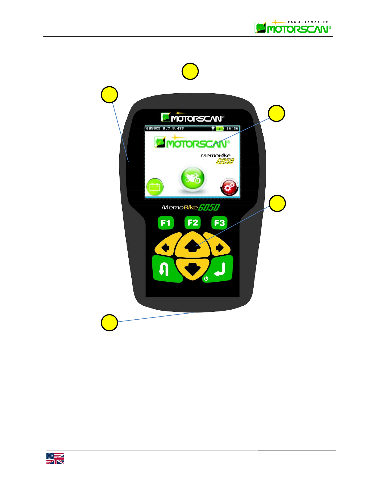
1.3 - FRONT / CONNECTIONS VIEW
1 ) LED LIGHT TO ILLUMINATE THE VEHICLE DIAGNOSTC SOCKET
2 ) USB INTERFACE FOR COMPUTER OR POWER SUPPLY CONNECTION
3 ) GRAPHIC DISPLAY
4 ) KEYBOARD
5 ) HD DB26 HD INTERFACE FOR DIAGNOSTIC CABLE CONNECTION
1
2
3
4
5

MS6050EN
MOD. 6050
OPERATING INSTRUCTIONS 9
1.4 - KEYBOARD VIEW
6 ) F1, F2, F3, KEYS : USE FUNCTION KEYS AS INSTRUCTED BY THE SOFTWARE.
7 ) KEYS : TO BROWSE THE SELECTION LIST OR TO MOVE THE CURSOR.
8 ) ENTER – ON/OFF KEY: TO PROCEED TO THE NEXT SCREEN OR TO SELECT A
FUNCTION.
9 ) ESC KEY : RETURN TO THE PREVIOUS SCREEN OR TO INTERRUPT A FUNCTION.
6
9 7 8
MOD. 6050
MS6050EN
10 OPERATING INSTRUCTIONS
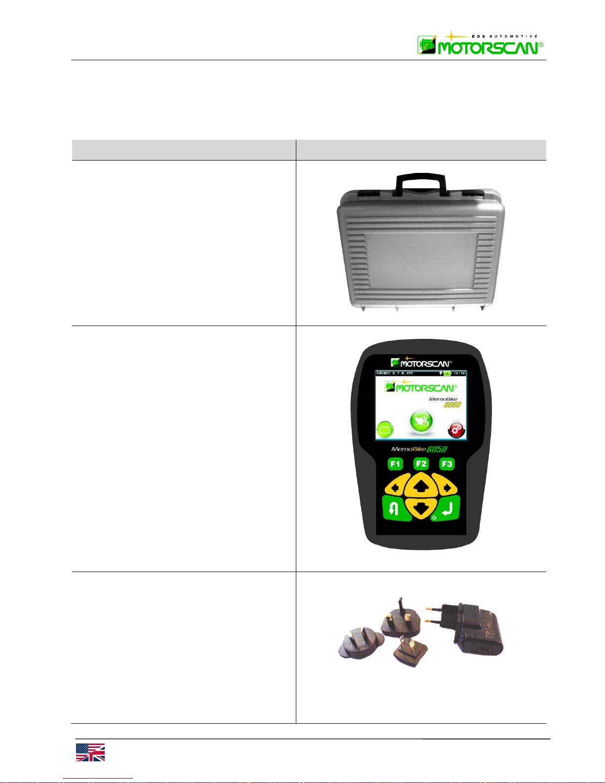
1.5 - STANDARD ACCESSORIES
Next to each motorcycle model in the “Vehicles List” you can find the part number for the cable
required for a particular function.
DESCRIPTION and PART NUMBER
PICTURE
Carrying case
Code: 22ST5600KP3*A
Scan tool
Part number: SL6050
AC/DC power supply
Part number: 2303W5V1AUSB
MS6050EN
MOD. 6050
OPERATING INSTRUCTIONS 11
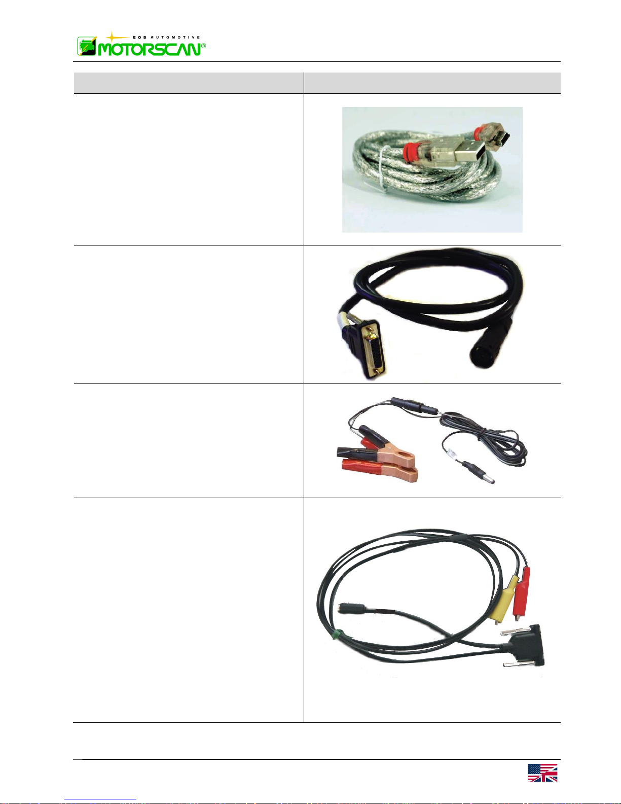
DESCRIPTION and PART NUMBER
PICTURE
USB/Power cable
Part number: 116000004
Master Cable
Part number: 520
Required for the use of the slave cables.
Battery power cable
Part number: 051
“Universal” Cable
Applications: Aprilia2, Benelli, BMW5,
Cagiva2, Harley Davidson3, Honda1,
Hyosung, Kawasaki5, Kymco, Malaguti2,
Mondial, Polaris5, Suzuki4, Sym, Triumph5,
Yamaha.
Part number: 522
1
Only blinking code and Hiss systems
2
Except Marelli systems
3
Only Marelli systems
4
Only display code systems
5
Except CAN-BUS systems
MOD. 6050
MS6050EN
12 OPERATING INSTRUCTIONS
1.6 - OPTIONAL
The part number for the cable required for a particular function is next to each motorcycle model
in the “Vehicles List”. Exact cables included vary by kit. Consult distributor.
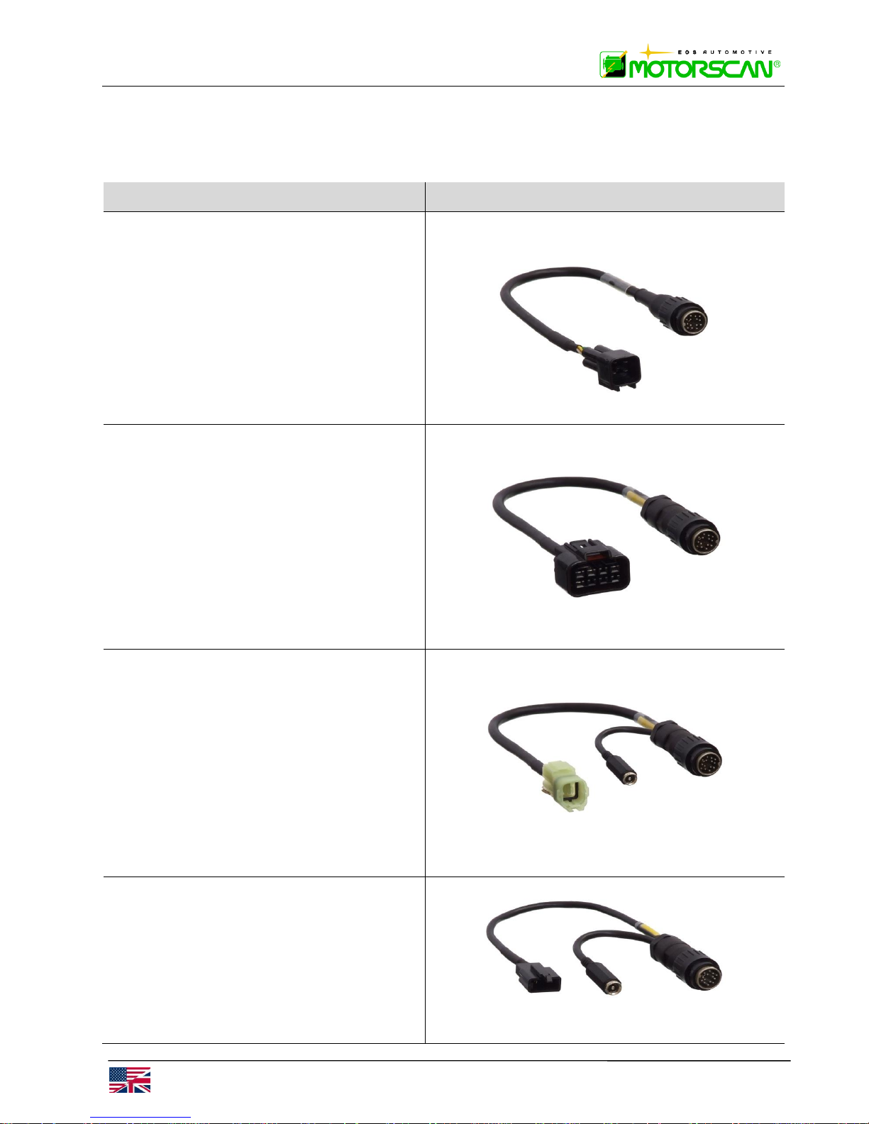
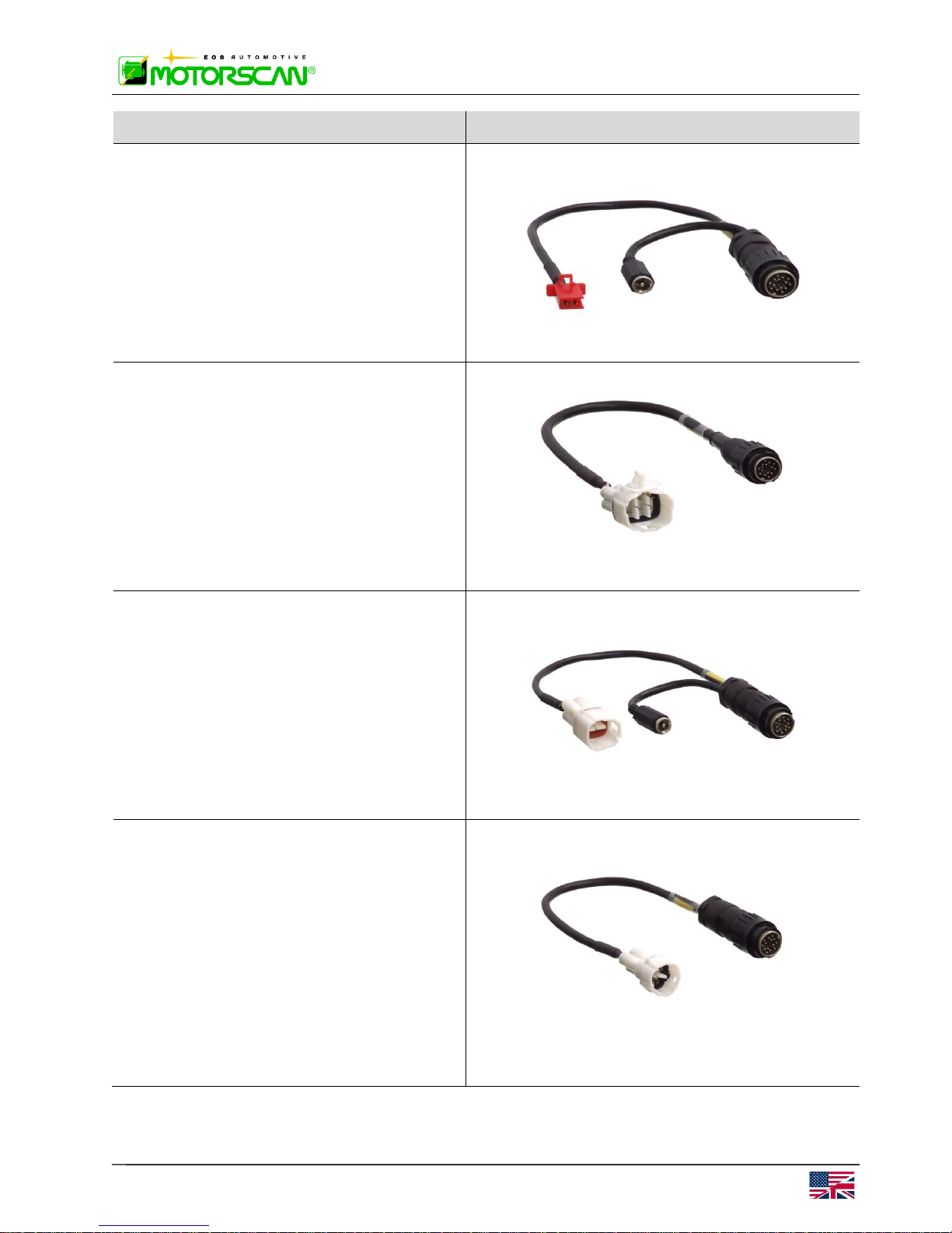
DESCRIPTION and PART N°.
PICTURE
KAWASAKI 4 Pin Slave Cable
Part number: 458
KAWASAKI 8 Pin Slave Cable
Part number: 459
HONDA 4 Pin Slave Cable
Part number: 460
WARNING: do not use on MV Agusta systems.
HONDA 3 Pin Slave Cable
Applications: Honda with blinking code
systems.
Part number: 461
WARNING: do not use on Aprilia/Ditech systems.
MS6050EN
MOD. 6050
OPERATING INSTRUCTIONS 13
DESCRIPTION and PART N°.
PICTURE
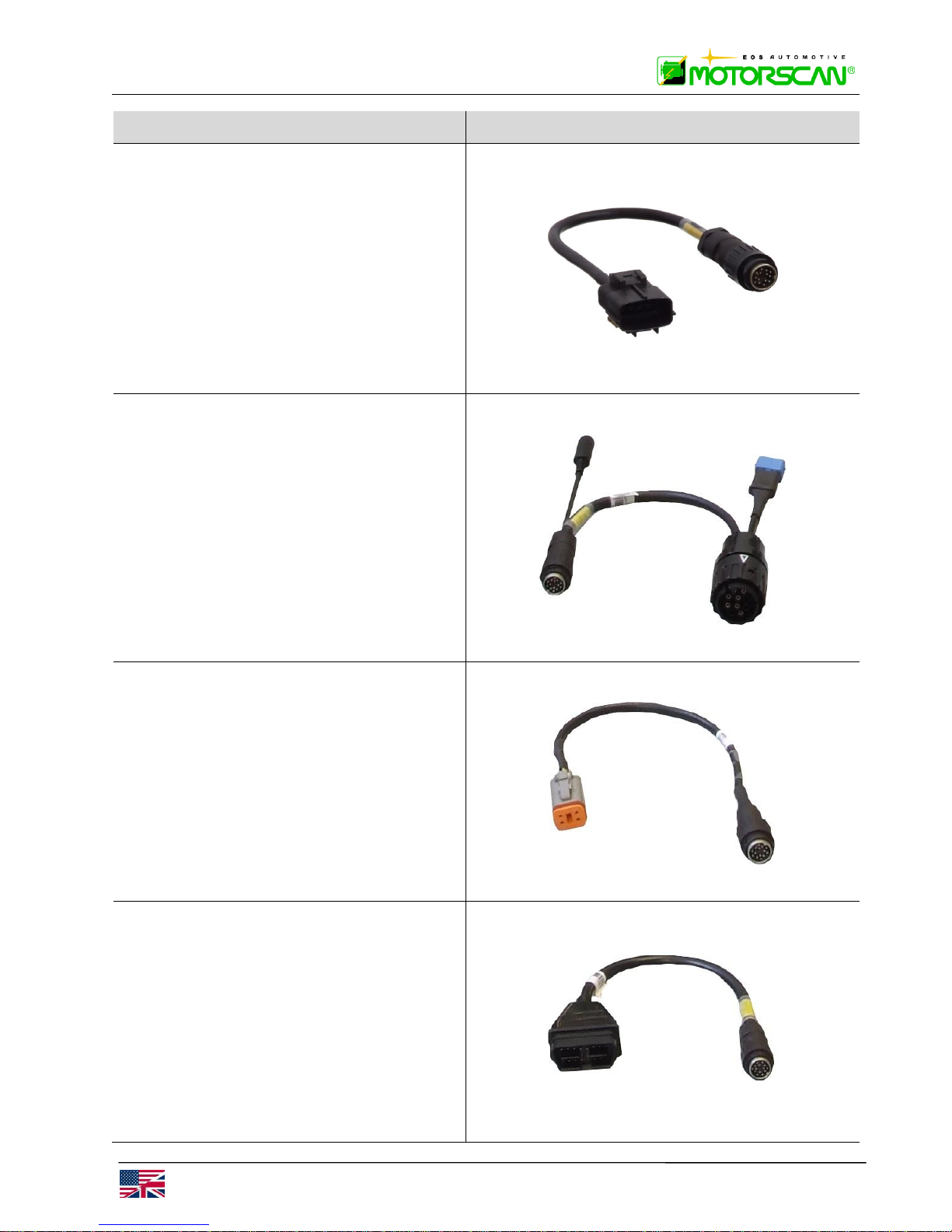
HONDA 2 Pin Slave Cable
Applications: Honda HISS systems.
Part number: 462
SUZUKI 6 Pin Slave Cable
Part number: 463
SUZUKI 4 Pin Slave Cable
Part number: 464
YAMAHA 3 Pin Slave Cable
Applications: Malaguti1 and Yamaha.
Part number: 475
1
Only Yamaha EFI systems
MOD. 6050
MS6050EN
14 OPERATING INSTRUCTIONS
DESCRIPTION and PART N°.
PICTURE
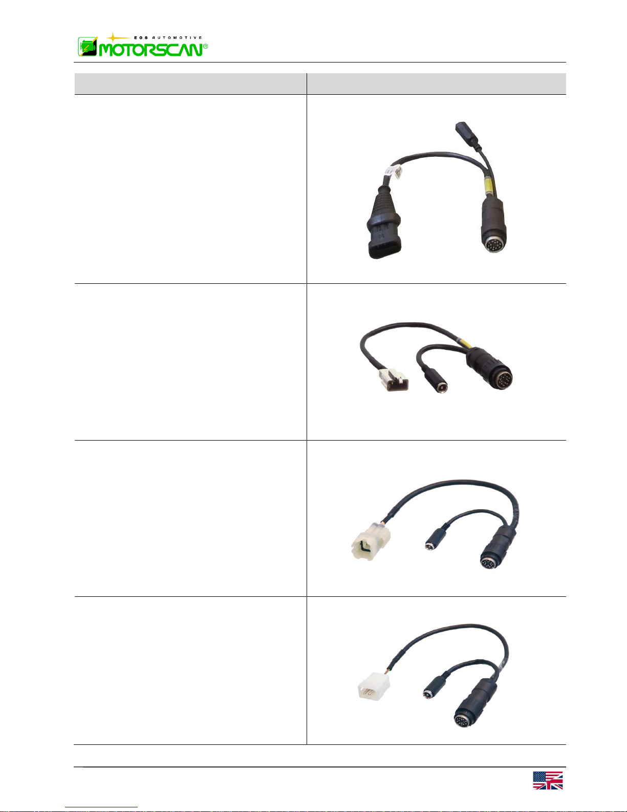
CAGIVA 10 Pin Slave Cable
Part number: 476
BMW Slave Cable
Part number: 525
Harley-Davidson Slave Cable
Applications: Harley-Davidson2 and Buell
Part number: 480
2
Except CAN -BUS systems
OBDII Slave Cable
Applications: Triumph
Part number: 481
MS6050EN
MOD. 6050
OPERATING INSTRUCTIONS 15
DESCRIPTION and PART N°.
PICTURE
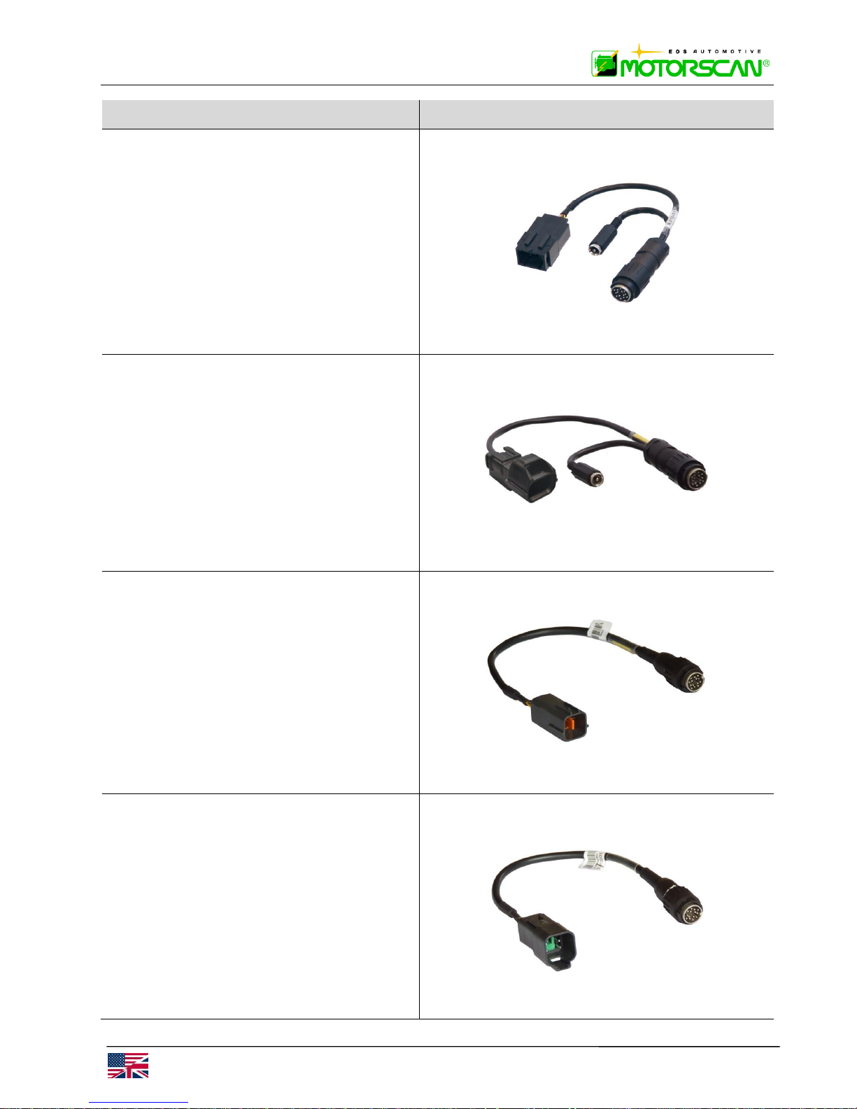
Packard Slave Cable
Applications: Aprilia1, Bimota1, Cagiva1,
Derbi, Ducati, Garelli, Gas Gas, Gilera,
KVN Motor, Laverda, Malaguti1, Moto
Guzzi, Moto Morini, MV Agusta1, Piaggio,
Sherco, Vespa, Voxan
Part number: 499
1
Only Marelli systems
APRILIA/DITECH Slave Cable
Applications: Aprilia Ditech system.
Part number: 483
WARNING: do not use on Honda systems.
KTM Slave Cable
Applications: KTM and Husaberg system.
Part number: 489
APRILIA/SAGEM Slave Cable
Applications: Aprilia Sagem system.
Part number: 490
MOD. 6050
MS6050EN
16 OPERATING INSTRUCTIONS
DESCRIPTION and PART N°.
PICTURE
PEUGEOT Slave Cable
Part number: 491
KYMCO Slave Cable
Part number: 493
KAWASAKI 4 Pin/2007 Slave Cable
Part number: 500
BRP Slave Cable
Part number: 501
MS6050EN
MOD. 6050
OPERATING INSTRUCTIONS 17
DESCRIPTION and PART N°.
PICTURE
KAWASAKI REG. INJ. Slave Cable
Part number: 502
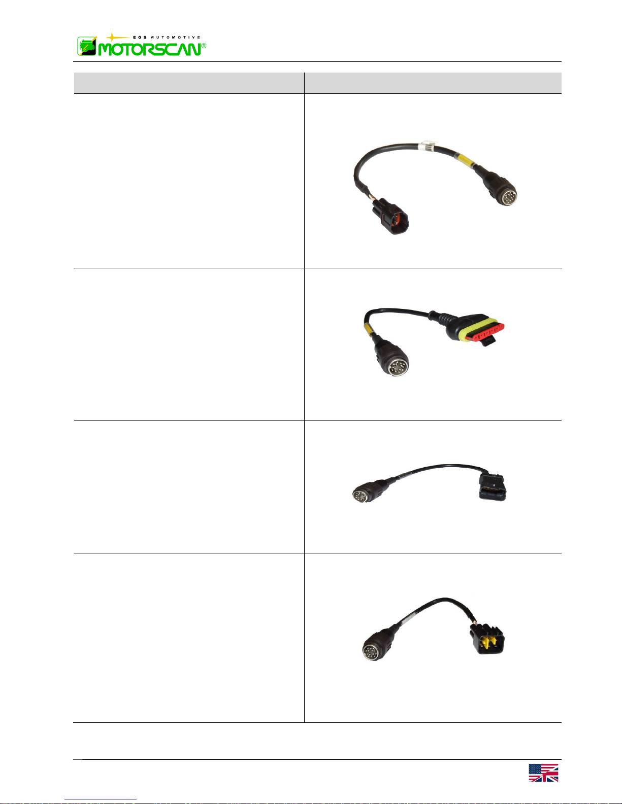
BENELLI 6 Pin Slave Cable
Part number: 505
DUCATI CAN 4 Pin Slave Cable
Part number: 508
KAWASAKI 6 Pin Slave Cable
Part number: 509
MOD. 6050
MS6050EN
18 OPERATING INSTRUCTIONS
DESCRIPTION and PART N°.
PICTURE
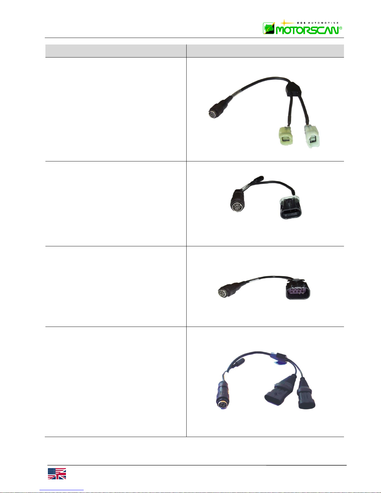
KAWASAKI MY 2010 6 Pin Slave Cable
Part number: 510
SYM 3 Pin Slave Cable
Part number: 512
POLARIS 8 Pin Slave Cable
Part number: 516
WALBRO SYSTEM Slave Cable
Applications: Aprilia and Bimota with
Walbro systems.
Part number: 518
MS6050EN
MOD. 6050
OPERATING INSTRUCTIONS 19
DESCRIPTION and PART N°.
PICTURE
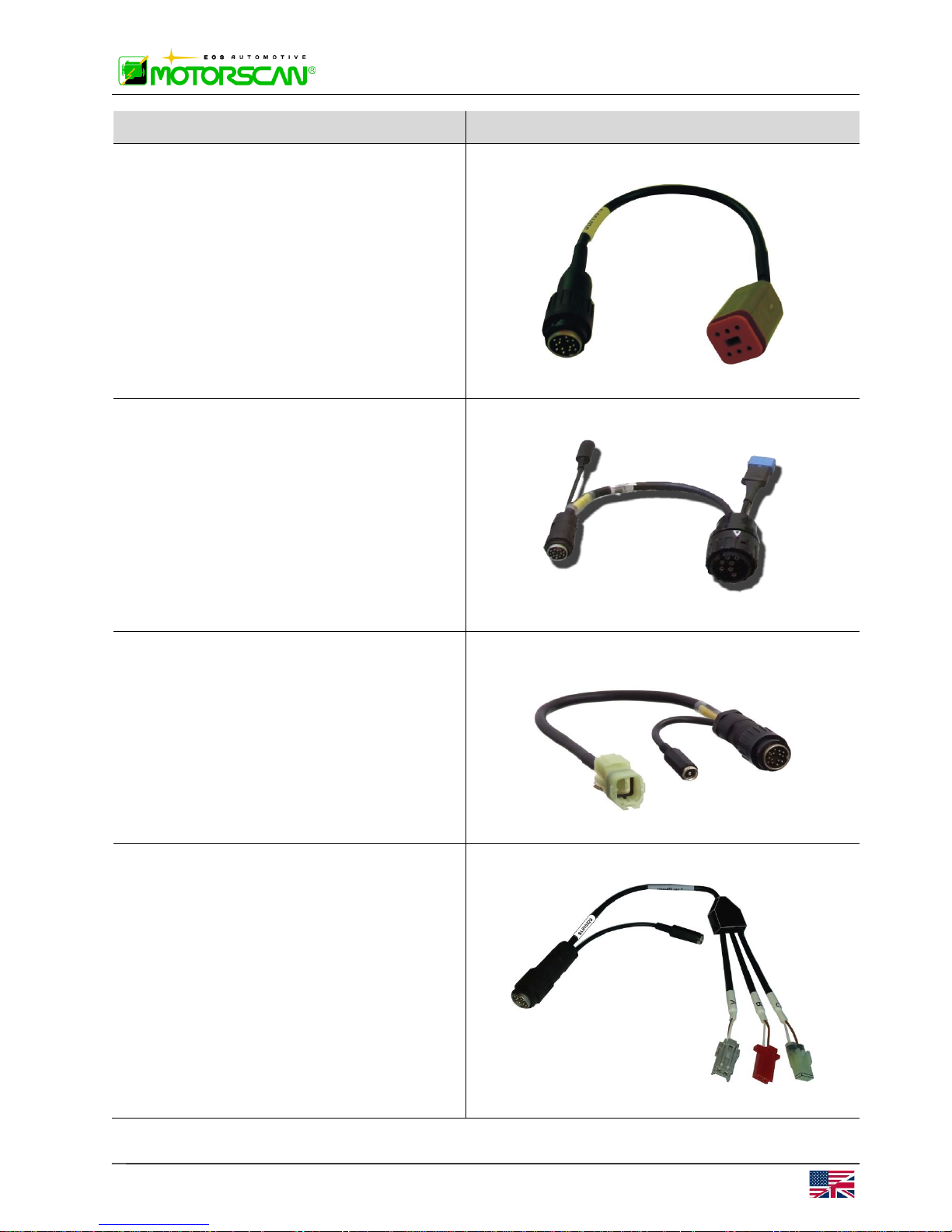
HARLEY-DAVIDSON CAN 6 Pin Slave
Cable
Applications: Harley-Davidson with CANBUS systems.
Part number: 519
BMW Slave Cable
Part number 525
MV AGUSTA CAN 4 Pin Slave Cable
Applications: MV Agusta with CAN-BUS
systems.
Part number: 526
WARNING: do not use on HONDA
systems.
HONDA HISS 2 Pin Slave Cable
Applications: Honda HISS systems.
Part number: 528
 Loading...