

SV-520/550 INSTRUCTION MANUAL
SV-520/550
l.Prior
2.Before
3.
4. heck lubri
5.
the u e
may
read it at
in
dicated
Ground
heck that
of
this product, please read the instruc tion
anytime
turn on the
in
ing th
cat
rotational direction
pow
the
contro
machine i always
ing oil
er
l box.
prior
when
be sure to
to op
necessary.
check
neces
erat
ion.
of
the
motor
For safe operation
Manual.
the pow r voltage and
ary
for
safe and norm al operation.
is
correct
prior to operation.
Keep this Instruction
phase
agre ing with the
Rev-5A
Manua
l and the user
nameplat
e that
6. So as to
cl
ose
7. For the following conditions , turn
8.
Repairing
prevent
to
the movi
7.1 or
7.2 To
7.3
7.4
7.5 When lightning and
, re
personal
ng
part
s. l o nev
threading
plug
or
unplug
For
mainten
When machine is not at u e, inspected
modeling
ance
and
injuries
needle
any
and repairing.
adjust
during
er
off
or
r pl
connecto rs from
thunder
ing
works must
operation be carefu l not to allow
try to stop it with external forces.
the
power
acing
occurs
or
disconnect
bobbin.
contro
or
.
only
l box.
adjusted.
be
done by a
the
powe
ppropriately
your
head and hands to
r plug from receptacle.
trained technician s
come
or
specially skilled personnel.
I.
Set
up
1.For
Dimensions
control
of
box
control
set
up
GTJ
r
box
as shown in Fig. I
lit
J~
-~
@
~
_J
c::=c::=-
---=:J
---=:J
H
301.05
290.75
301.6
328.77
235
- r
-
,
J
"1
7
~
~
=1 -'-
10.25
~1
'-
',;,
{s
I
~
I $n o $1
0 0
en
@ = @
0 0
D
[]
JJ~
t'i
~
Fig.I
I. Set up
I .For motor & control box set up
Dimensions
of
motor & control box as shown in Fig. I
330
•••••
300.5
(".)
<O
C\J
""'"
If)
C'\i
cO
8
0
0
D
0
()
fl
D
DO
CJ
@
e
Fig.I
2.
Connector position and function
Circuit boards as Fig. 2 . Table 1 is the explanation for the connectors. Connectors for control box external
output please refer to Fig 3, then according to the machine, connect it to the respective connectors.
-)
CK2~
••
••
••
••
CN3
::
••
••
•
Connector
CN3
CNS
CN4
Fig.2
Option IN_I: pin 5
Option
Option IN_B : pin 9
Option IN_C : pin
IN_A:
pin 7 & 8
• m
CH5~
CN6~
CN
CNS~
7
:
:
rn
ctUJ~
CN
DUI~
CN
l6
9 e •
•
Connectors ' description
CO2
Front cover
Motor encoder connector
Standing operation pedal connector
& 6
&
10
11 & 12
connector
m
.
e e
[;}
..
••
• •
• •
••
CN13
CN14
CN7
CN6
External Panel connector
Speed unit connector
Safety switch connector
Synchronizer connector

CN9
CNll
CN16
CN15
Machine functions' connector
Option
Option
Option
Option
Foot lifter switch
Back tack switch
OPTION D connector
Option
Option
Option
OUT_B:
OUT_E:
OUT_F:
OUT_G:
IN_K: pin 2 & 6
IN_L:
IN M : pin 4 & 6
pin 6 &
pin 2 & 9
pin 1 & 8
pin 7 &
: pin 4 &
:pin5&12
Foot lifter Solenoid connector
pin 3 & 6
Material edge sensor connector
11
13
14
1---i~
3--~--r
0
CNS
CN12
Foot lifter discharge resistor
+12V Power output connector
Table 1
0
1-
2--0{]
3--{]
i
4-osJJ
5---+--
0
Fig.3
See Fig. 3
I .Motor power line connector.
>------le---
0
10
4--0
I .Motor power line connector.
.JJ
1---------l-
0 0
Fig.4 ·
See Fig. 4
11
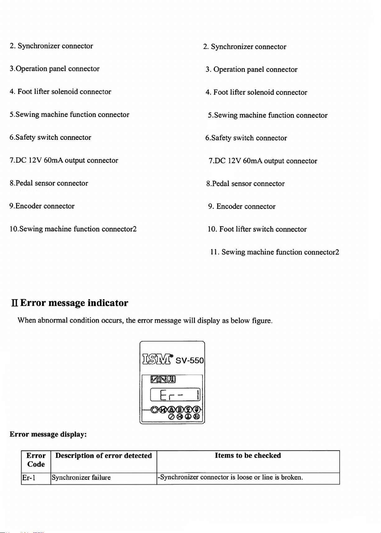
2. Synchronizer connector
2. Synchronizer connector
3.Operation panel connector
4. Foot lifter solenoid connector
5.Sewing machine function connector
6.Safety switch connector
7.DC 12V 60mA output connector
8.Pedal sensor connector
9.Encoder connector
10.Sewing machine function connector2
3. Operation panel connector
4. Foot lifter solenoid connector
5.Sewing machine function connector
6.Safety switch connector
7 .DC 12V 60mA output connector
8.Pedal sensor connector
9. Encoder connector
10
. Foot lifter switch connector
11.
Sewing machine function connector2
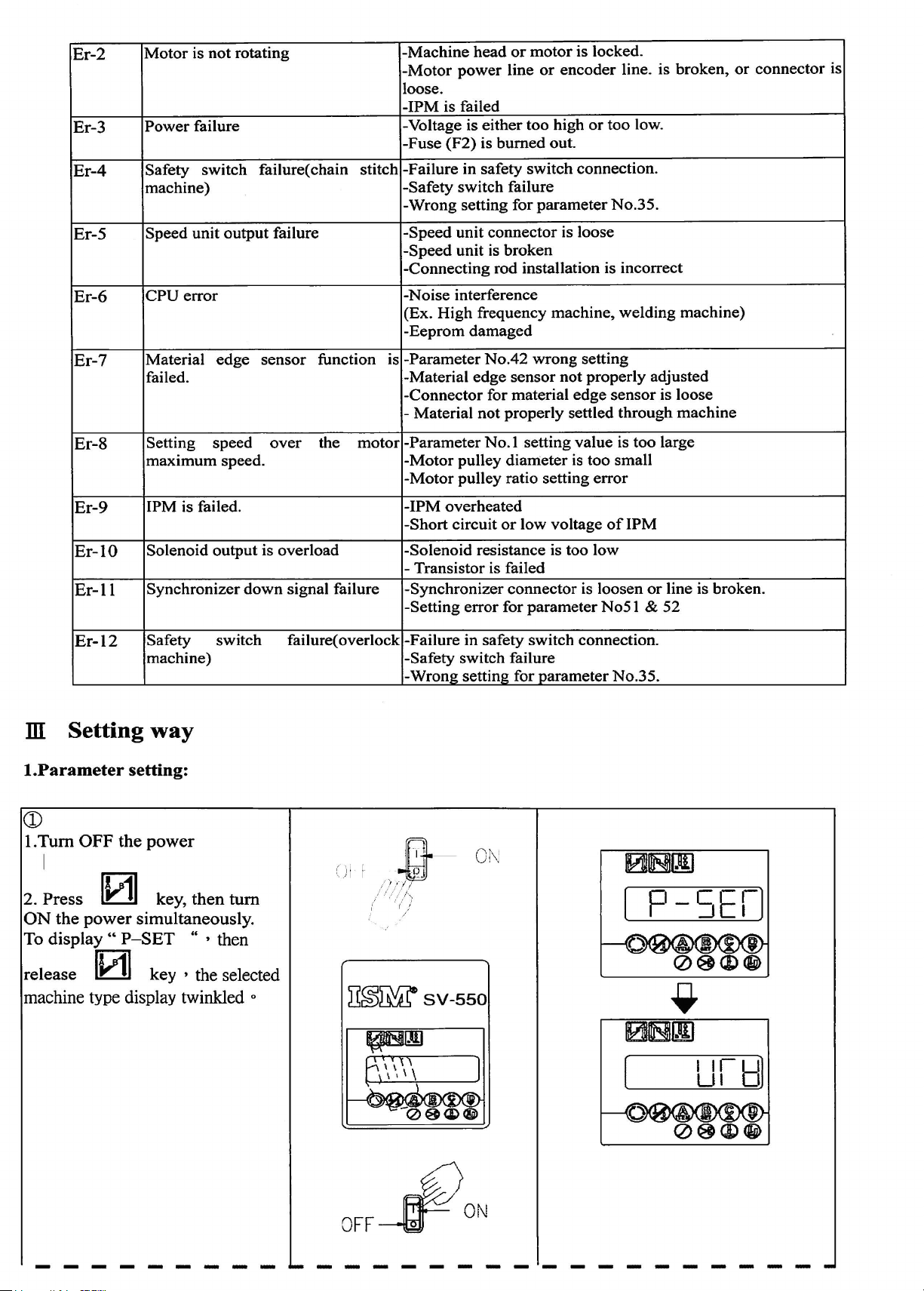
Il Error message indicator
When abnormal condition occurs, the error message will display as below figure.
~~Wsv-550
[ Er -
I]
Error message display:
Error Description
Code
Er-1
Synchronizer failure
of
error detected
-Synchronizer connector
Items to be checked
is
loose
or
line
is
broken.
Er-2
Er-3
Motor
Power
is
not
failure
rotating
-Machine
-Motor
loose.
-IPM
-Voltage is
-Fuse
power
is failed
(F2)
head
either
is
burned
or
line
motor
or
too
high
out.
is locked.
encoder
or
too
line. is
low.
broken,
or
connector
is
Er-4
Er-5
Er-6
Er-7
Er-8
Er-9
Er-10
Er-11
Safety
machine)
Speed
CPU
Material
failed.
Setting
maximum
1PM is failed. -IPM
Solenoid
Synchronizer
switch
unit
error
speed
output
failure( chain stitch
output
edge
speed.
failure
sensor
over
is
down
overload
signal failure
function
the
-Failure in safety
-Safety
-Wrong
-Speed
-Speed
-Connecting
-Noise
(Ex.
-Eeprom
-Parameter
is
-Material
-Connector
Material
-
motor
-Parameter
-Motor
-Motor
-Short
-Solenoid
- Transistor is failed
-Synchronizer
-Setting
switch
setting
unit
connector
unit
is
rod installation is incorrect
interference
High
frequency
damaged
No.42
edge
for material
not
No.
pulley
pulley
overheated
circuit
resistance is too
error
switch
failure
for
parameter
is loose
broken
machine,
wrong
sensor
properly
I setting
diameter
ratio setting
or
connector
for
not
edge
settled
value
is
low
voltage
parameter
connection.
No.35.
welding
setting
properly
sensor
through
is
too
too
small
error
of
1PM
low
is loosen
No5
or
l &
machine)
adjusted
is loose
machine
large
line is broken.
52
Er-12
ill Setting
I.Parameter
Safety
machine)
way
setting:
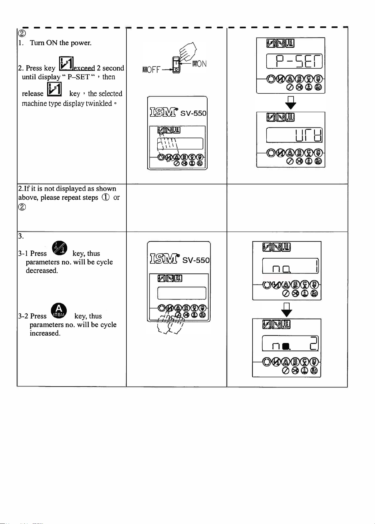
CD
I.
Tum
OFF the
I
2. Press
ON
the power simultaneously.
lv11
To display
release
machine
IWI
type display twinkled
power
key, then
..
P-SET
key , the selected
switch
tum
" , then
0
failure(
overlock
CJ
I I
~~~SV-550
-Failure in safety
-Safety
-Wrong
.
-Gt
1///
/ ' i /·-...
i ( i
/
switch
setting for
-
Of\j
switch
failure
parameter
connection.
No.35.
OFF
PON
----------------------------
®
I. Turn
ON
the power.
2. Press key
until display
release
machine type display twinkled
2.lf
it
is
above, please repeat steps
0exceed
"
P-SET"
[1/1]
not displayed as shown
key , the selected
2 second
' then
®
3.
CD
0
~~~SV-550
or
Pres~ • key, thus
3-1
parameters no. will
decreased.
3-2 Press
parameters no. will be cycle
increased.
• key, thus
be
cycle
il~SV-550
101B[J]
[
(
no
na
I]
2)
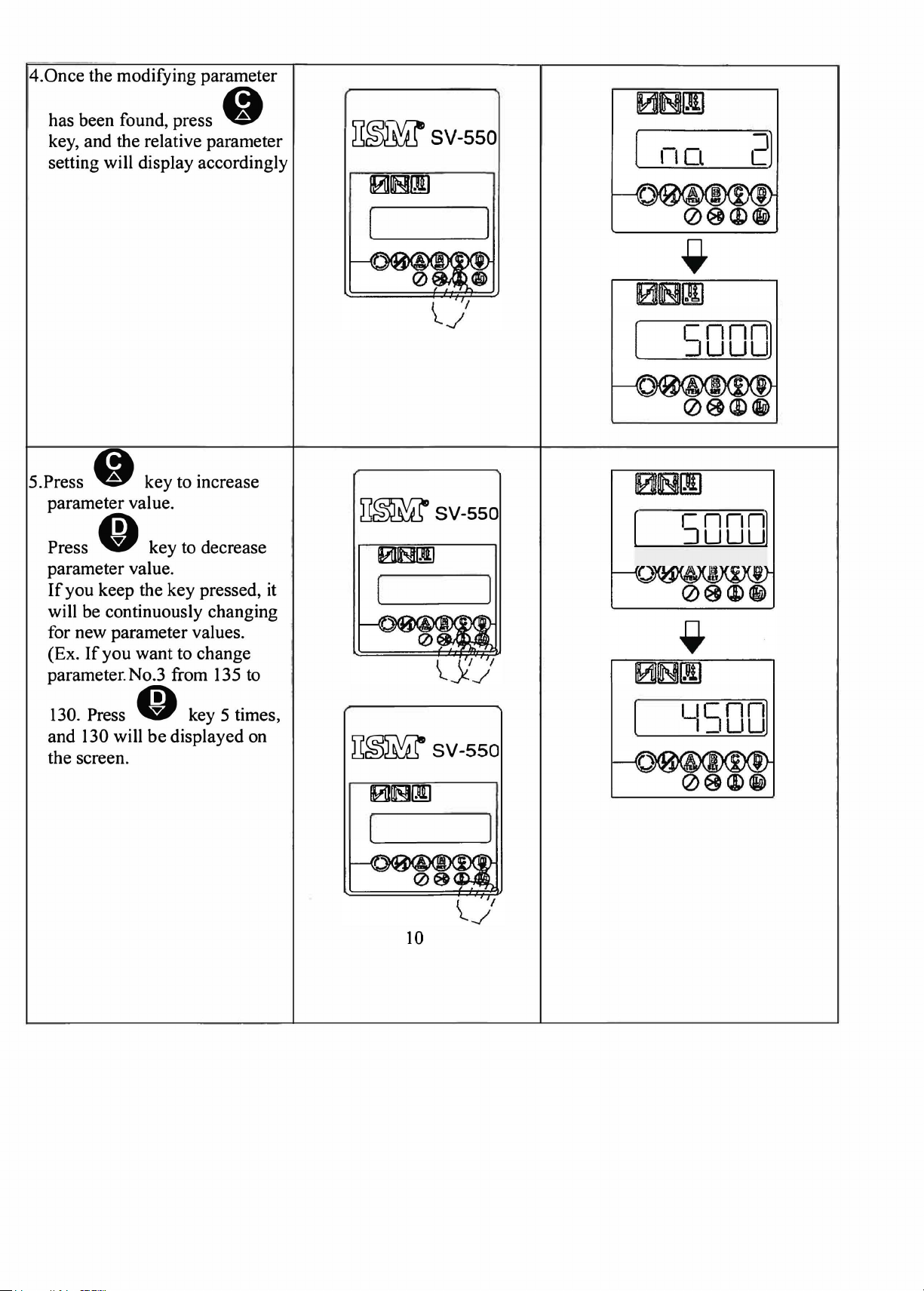
4.Once
the modifying parameter
has been found, press •
key, and the relative parameter
setting will display accordingly
~~SV-550
2)
101ms![IJ
5.Press • key to increase
parameter value.
Press
parameter value.
If
will be continuously changing
for new parameter values.
(Ex.
parameter.No.3 from 135 to
130. Press
and 130 will
the screen.
• key to decrease
you keep the key pressed,
If
you
want to change
O key 5 times,
be
displayed on
it
D~sv-sso
ims!~
~~SV-550
[
(
[
5000)
50001
'~SOD]
0~111
10

6.Pressing • key can selec~
for the next parameter no.
repeat steps 4-6 to modify
parameter value.
7 .Once all specified value has
~~SV-550
0~
r1c1
----
- f
-,i,
been changed, press
to save.
performed, the specified value
will
8.Tum
re-start the power, thus it will
operate according to
parameter values
not
OFF
If
this procedure is
be
updated.
the
power
Okey
then
new
not
ra·-.
w-i:
-~~
--·
=~
,,__J
I\ .
D~~SV-550
I
2.Motor pulley ratio measurement :
I.Tum
OFF
the power.
J'·
"'
·-;.
~.'
; I ,
1· ,
•.

2.Press O key, then turn ON
the power. Release • key.
If
the display
3.
is
not as shown
above, please repeat steps 1-2.
~~SV-550
------
~r"WLlw=•
-'<Y
0 s
111.JI'~
~
t ) \ I I \
\
-
,1UIJ-
j~
'F~'
I
__
II
---
-
'
4.
If
the pedal is forwardly
pressed, the motor will rotate 7
turns at positioning speed. After
the motor stops, the motor
pulley ratio will be displayed.
(Sewing machine
360°=motor?
degrees). The step 4 can be
repeated
to
confirm.
'
-... -.
-~~
=-~
-::.~ --~~
--
--.-·--·
I I
...
-·_: --.
c::-:_----\
.J
_../-.·::,
-
_,;,;;..
____
.-
---
·
' .
::::
--
--
: \ .
-;-
I J
-,
--~ c): n; I
-'/ ,/
..
~.
1.-~ I
' . . . . .
~
~-
J
..
__

5.Press @ key to save.
procedure is not performed, it
will remain as the old values.
6.Turn
ON
power
the power, It will operate
then re-turn
OFF
the
according to new pulley ratio
values.
If
this
~~SV-550
0~
-
,-
.~
y y '
;
,.
..
,,
..
,'
,..'
',/
tr@r-"i~-=x
~71°'~~5fft~
A{ -lJc If -
~-
...
'•'
'\
'
..
··
..:..
-,
c I
CCI
- -
--~
D~~SV-550
--
Ii
·'
3.Select the machine type :
I.Tum
2.Press
OFF
the power.
G key
simultaneously, then turn
the power, until rESET
displayed then release the key.
ON
~~SV-550
~eoo
- - -- - -----
_
Cc
_ I
C
I,_
!=
. 1
' j't
I !

3.If
it is not displayed as shown
above, please repeat steps 1-2.
4.Use A, B,
password. And enter
to confirm.
C,
D key to i
in
r•
1/1
~~~SV-550
~~~SV-550
~~
l~l1tLn
I
11_1_
I
I_I
:
IFf
5.If
the password is correct, the 1
sewing machine head choice
will be displayed.
password is incorrect, the
"PW-ER" will be displayed.
Please repeat step 4.
If
the
st
r~,zt~tif
' --
---
-·
-- -
--
.J

6.Press key to select
machine type, then
~~SV-550
,
___
·1
_
press.
Tum
7.
OFF the power, then
ON
the power again. It will
operate according to the
manual's instruction initial
value.
key .
tum
01E!III
~~SV-550
10IBIII
.....
,,..--·
....
'
·- - ·
l~
t~~Jtt~
·--------
~~~SV-550
0~
- -
··
l
;:....,
_
_)
5.Historical error message display
1.
Turn OFF the power.
THi
,
;
i.
'~H! r
-
/.'/
/·
•1,
/,/ ,
tt
'
'·

2.
Press O key, then tum ON
the power simultaneously and
display "ERROR"
~~SV
-550
~
{ '; ,'i,
., .....
. : .J --~
C n
..
;-
-··~ .
2.1 Release
display recent error message.
3.Press key to cycle display
recent 6 error messages.
O key and will
~~~SV-550
\.
__
,/
Er
I
I
6.Pedal sensor neutral point setting mode
I .Tum OFF the power
;-:._:-;'
I
J
~
'''
.
' p

2.
Speed unit (Pedal sensor) pedal
sensor in the neutral point.
Press
the
display "OFSET".
3. Release
display
was stored in EEPROM.
4. Once pressed
the pedal sensor again.
value between 1340-1790, press
• key, then tum ON
power-simultaneously and
• key, and will
the pedal sensor value that
• key, read
If
the
~~~SV-550
"-J
• key to save the value.
5.
If
always displays "ERROR" that
means the pedal sensor neutral
point offset is too much. The
pedal sensor mechanical neutral
point must be adjusted then repeat
step 4.

IV SV-520/550 series Control box parameter list:
No
1
Sewing machine maximum speed
'
2 ,
Sewing
Sewing machine positioning speed
3
Sewing
4
5
The
' Soft start speed
6
7 Soft start stitches
Condensed sewing speed / End auto back
8
tack soeed
End condensed stitches' number
9
10
Stitches' number that between condensed
sewing and trimming
machine medium speed
machine trimming speed
speed
of
start auto back tack
Item
200spm
200spm
I00spm -250spm
I00spm -250spm
500spm
250spm
0
500
0
0
- 8000spm
-
-
-
19
stitches
-
- 2500spm
99 stitches
-
19
stitches
-
8000spm
2500spm
2000spm
Ranl!e
Remarks
50 rpm/step
50spm
I
I step
lspm
/ step
lspm / step
I0spm
/step
I0spm /step
I0spm
/step
Foot lifter type
11
12
Foot
lifter control mode PFL: Pedal controls foot lifter.
Delay time after foot lifter is
13
Confirming time for foot lifter acting level
14
15
Foot lifter duty
down
SOL: Solenoid type
AIR: Pneumatic type
TAFL: auto foot lifts after trimming
AFL: Auto foot lifting after positioning
TFL: Pedal controls foot lifter after trimming
SFL: Auto foot lifting (Material edge sensor
control)
AFL2: Auto foot lifting after trimming.
even pedal forward)
100 - 2500 ms
1000 ms
-
10
0
- 99%
(It's
as
output
effective
10
ms/
step
10
ms/
step
1 % / step
Foot
16
lifter ful I duty output time
100
-
1000 ms
10
ms/
step

Thread trimming mode
17
OFF : No thread trimming
I
Thread trimming delaying time 0
18
19
Thread trimming acting time 0
20
Thread wiping delaying time 0
LOCK : lockstitch
LU2 : LU2220 thread trimming
LUI : LU1520 thread trimming
LU:Other LU machine thread trimming
US639 : US63900 thread trimming
UT : Needle up trimming
AIR:Needle up trimming (AIR BLOW)
UT2:Needle down trimming (trimming
& wiping together)
200ms
-
lOOOms
-
300ms
-
thread trimming
10
10
10
ms/
ms/
ms/
step
step
step
Thread wiping acting time
21
22
23
24
25
26
27
28
Foot lifter delaying time
Thread wiping output control 0 : No output thread wiping
Motor rotating direction
A_ code back tacking compensation 0
B _ code back tacking compensation
C _ code back tacking compensation
The curve slope
rotating speed
of
pedal stroke vs. motor 0
0
2500
2500
no·
no·
no·
4
ms
ms
-
0
-
I : Output thread wiping
2 : Output thread wiping when foot
lifter active
CCW : Counterclockwise
CW : Clockwise
-
0
-
0
-
-
Bigger value means smaller curve slope
10
ms/
10
ms/
5
• /step
5
• /step
5 • /step
step
step
I
I
29
18S
Motor
type
select
Slowdown speed select at auto
turning point
backtack
6535 : 650 W / 3500 rpm
5535 : 550 W / 3500 rpm
5560 : 550 W / 6000 rpm
5550 : 550 W / 5000 rpm
6560 : 650 W / 6000 rpm
4550 : 450 W / 5000 rpm
5070 : 500 W / 7000 rpm
3570 : 350 W / 7000 rpm
3570 < 5070 < 4550 < 6560 < 5550 < 5560 < 5535 <
6535
0
.....,
3

30
The pedal stroke adjustment for motor 150 - 90
rotating (Pedal
neutral=
40, LOI lighting)
31
Pedal stroke adjusts for motor accelerating 70
32
Pedal stroke adjusts for foot lifter acting
33
Pedal stroke adjusts for start thread 3 - 30
trimming
34
Standing type pedal operating choice
Safety switch type
35
In auto test mode, motor running time I 00
36
adjustment
-
110
10 -35
OFF:
Normal speed pedal unit
PK70:
For JUKI standing operation
PK70 type
PKSW: Standing pedal operation, the
speed is fixed (low speed
PK71 : For YHH standing operation
PK71 type
N.O:
Normal open switch
N.C:
Normal close switch
- 20000
ms
& high speed)
100
ms/
step
In auto test mode, motor stopping time I 00
37
adjustment
Back tacking switch function
38
- 20000
BTSW : Control back tacking solenoid
NDUP : Control back tacking solenoid when motor
runs, and as needle up switch when motor stops
DSIN : Control back tacking solenoid when motor
runs, non-continuously inching during motor stops
CNIN : Control back tacking solenoid when motor
runs, continuously inching during motor stops
IRFSS
both during sewing and stopping
: Reverse feed stitching function is effective
UPBT : Control back tacking solenoid only in up
position
SHOT : Control back tacking solenoid, No.74 decide
the output pulse width.
ms
100
ms
I step
FLIP : Control back tacking solenoid,
by flip-flop type output
Stitches' number in reverse feed stitching
39
Trimming function in the reverse feed OFF: Ineffective
40
stitching ON: Effective
-
19
0
stitches

41
Execute auto thread trimming after end fixed
stitches' number sewing process
42
Material edge sensor function OFF: Ineffective
Material edge sensor stitches' number
43
44 Use material edge sensor to process
trimming function
45
Auto needle up positioning when power on OFF: Ineffective
OFF: Ineffective
ON: Effective
ON: Effective
O
0:
I : Auto trimming after execute the step-I stitches.
2 : Auto trimming after execute the step-2 stitches.
3 : Auto trimming after execute the step-3 stitches.
4 : Auto trimming after execute the step-4 stitches.
ON: Effective
--
250 stitches
No
such function.
46
47
48
49
50 The
51
52
53
Backtack switch protect time
To lock the pedal forward
finish trimming process ON: Effective
Sewing machine reversed revolution
function after thread trimming processed ON: Effective
Sewing machine reversed revolution angles 0
after thread trimming processed
delaying
trimming
reversed revolution.
Virtual needle down positioning function
The angles between virtual needle
positioning point and needle up signal
The needle positioning function
sewing
time
but before sewing machine
function before
after finished thread 0
down
of
starting
--
3 0 seconds
0
OFF: Ineffective
OFF: Ineffective
--
250°
--
2500 ms
OFF: Ineffective
ON: Effective
0
--
250°
OFF: Ineffective
ON: Effective
1 ° / step
10
ms/
l°
/ step
step
54
The needle
sewing
55
The starting angle
(count from the needle down position and
only effective
56
The continuous angles
(count from the needle down position and
only effective
positioning angles
of
trimming action
in
LU
trimming mode)
of
trimming action
in
LU
trimming mode)
of
starting
0
--
250°
0
--
250°
0
--
250°
1 ° / step
1 ° / step
1 ° / step

57 The
58
59
60
61
tension
(count from the needle down position and
only effective in LU trimming mode)
The tension release continuous acting angles 0
(only effective in LU trimming mode)
The tension release continuous acting time
( count from the needle up position and only
effective
The function choice
The function selection for Option IN_B
release
in
LU trimming mode)
starts
of
Option IN_ A
acting
,..._,
angles 0
250°
,..._,
250°
0
,.._,
1250
ms
OFF : No function
DSCT: Cancel thread trimming for one time
DSBT: Cancel auto back tacking for one time
DSCN : Cancel condensed stitching for single time
NDUP : Needle up switch
l°
/ step
1 ° / step
5
ms
I step
(it's
only effective
when No.34=OFF)
62
Option IN_P 0 : Stop switch
The function selection for option
(only SV-520 effective)
63 Motor stop before executes EBT
Motor stops time before executes EBT
64
(only effective when No.63=ON)
65
Breaking thresfold 130-250
JN
_ P
HALF : Half stitch inching
ONE : One stitch inching
1
: Stop switch (flip-flop type) • output OUT_E
active
when
2 : Cancel automatic backtack switch • output OUT_E
when active
OFF : ineffective
ON:
20
effective
,..._,
1500
ms
10
ms/
step
66 Slight breaking action time 10-50ms
67
Slight breaking speed
200-l 700rpm
68 Slight breaking function OFF: Ineffective
ON: Effective
The Option OUT_A acts stitches'
69
after material edge sensor on
number
0
,..._,
99 stitches

The Option OUT_A delays stitches' number 0
70
after material edge sensor
The acts stitches' number after the Option 0
71
OUT_A delays stitches' number
edge sensor
off
off
& material
.......
99 stitches
,.._,
99
stitches
The Option OUT_B acts stitches' number O
72
I after material edge sensor on
The Option OUT_B delays stitches' number O
73
after material edge sensor
74
The Option OUT _B acts time
The Option OUT_C acts stitches' number
75
after material edge sensor on
The Option OUT_C delays stitches' number 0
76
after material edge sensor
The Option OUT_D acts stitches'
77
after material edge sensor on
78
The Option OUT _D delays stitches' number 0
after material edge sensor
off
off
off
number
0
O
O
,.._
,.._
.......
---
.......
.......
---
99
stitches
99 stitches
250
ms
99
stitches
99
stitches
99
stitches
99
stitches
79
The function choice
80
The function choice
80
The function choice
0:
of
Option OUT_A
of
Option OUT_B
of
Option OUT_B 3 : Depend on the setting stitches' number output
No output
I : Depend on the setting stitches' number output
Depend on the setting stitches'
2 :
when foot lifter acts
No
3:
0:
I : Depend on the setting stitches' number output
(Pedal control speed)
2 : Depend on the setting stitches' number output
(material edge sensor starts
speed)
(material edge sensor ends
speed)
output when motor stop
No
output
& during motor medium
& during motor medium
number output

81
The
function
choice
of
Option
OUT_
C
0:
No
output
I :
Depend
(Pedal control speed)
2 :
Depend
(material
speed)
on
on
edge
the
the
setting
setting
sensor
stitches'
stitches'
ends & during
number
number
motor
output
output
medium
82
83
84
3 : Auto
without pedal press
The
function
The
control solenoid
material
edge
choice
sensor
of
Option
output
OUT_D
cycle
choice
0:
No
I :
Depend
2 :
Depend
when
3 :
Depend
number
motor
of
O : Option OUT_A
1 : Option OUT_B
2 : Option OUT_C
3:
None
The
priority
on
& pressing pedal forward pressing pedal
between
material
edge
sensor
O :
The
I : Pedal condition is
material
sewing
output
material
edge
the
on
the
on
foot lifter acts
on
the
output
stops)
sensor
setting stitches
setting stitches'
the
setting
setting
(keeps acting
edge
on
stitches'
stitches'
sensor
immediate
number
even
must
output
number
be
acted
effective
output
before
when
85
Cancel
when
the
thread
pedal is heeled. is heeled
trimming
function
choice
2 : Pressing pedal is prior.
OFF
: With
ON : Cancel
is heeled.
effective.
the
the
thread
thread
And
trimming
trimming
just
function
function
the
foot lifting function is
when
when
pedal
pedal

Special function choice
86
No
special function
0 :
I : LB2 enable, MTJ=OFF
2 : LB2 enable, MTJ=
3 :
BAF
function
521
4 : LUI
5:
CAI
6 : SAS I function
7 : BASF function
8 : Manual one- shot function
9 : Automatic one-shot function
10
: edge sensor with re-cycle function
11:
auto sewing when use PKSW
jy
12:
13:
FW740 function
function
function
tunction
ON
No
87
88
89
90
91
synchronizer operation mode
The speed margin
positioning
Decelerating speed slope choice
Motor static brake function
Motor rotation signal control
of
executing needle
14: FW730 function
OFF : ineffective .
ON : effective
80
,._
160
1
,._
8
(The bigger value means the longer time of
decelerating.)
0 : No such function
"'
1
powerful braking force.)
OFF : No output
TL
TL2 :
TL3 : TL solenoid control by edge sensor
20 (The bigger value means the more
I : TL solenoid outputs when motor rotates.
TL
solenoid outputs when motor rotates & foot
lifter acts.
1 /
step
TIA : TL solenoid control by edge sensor and Interval
stitch
TL5 :
TL
solenoid control by Interval stitch
92
Forward output the motor rotation signal
0
-----
1250
ms
5
ms/
step

93
Current limit table boost
up
......
0
20
94
95
96
97
98
99
100
101
Reverse
stitching.
Check the speed control unit condition
function when
Alarm signal output function.
Auto function setting. OFF: Ineffective
(Only effective in BAFS machine)
Motor
(Only effective in BAFS machine)
BLOWER-B
(Only effective in BAFS machine)
I
BLOWER-B
(Only effective in BAFS machine)
In motor running,
control
angles when
power
delays starting time. 0
delays output time.
output time.
FLSW
FLL
output acted stitches'
machine starts 0 --250°
on. ON: Effective
key
input to
number
OFF: Ineffective
OFF: Ineffective
ON
: Effective
ON: Effective
....,
9900 ms
0
......
9900
ms
--...
9900
00
ms
stitches
0
0
- 5
1 ° / step
100
ms
/ step
100
ms/
step
ms/
100
2 stitches/ step
step
102
103
Material edge sensor begins acting, Option
OUT_E delay acting stitches number
Material edge sensor ends acting, Option
OUT_E
104 Option
105
106
107
108
Foot lifter protecting time
Folder auto function setting
(Only effective in TCF machine)
Folder auto function delays stitches ' number 0
(Only effective in
Motor's braking force when positioning
continuously act stitches number
OUT
_E function choice
TCF
machine)
- 99 stitches
0
0
- 99 stitches
OFF : No
ON : Depend on setting stitches'
0
-
OFF: Ineffective
ON: Effective
- 99 stitches
- S
0
60
seconds
output
number output
1 seconds / step
109
110
111
Quick Needle positioning function
Motor positioning stopping force 0
ER-2 checking time 0
OFF: Ineffective
ON: Effective
,.._,
5
5 seconds
-
1 seconds / step

112
ATC auto function setting
(Only effective in ATC
machin~)
OFF: Ineffective
ON: Effective
113
114
115
116
117
118
119
Material edge sensor begins acting;Option
OUT_F delay acting stitches' number
Material edge sensor ends acting, Option
OUT_F continuously act stitches' number
Option OUT_F function choice OFF :
Control Option OUT_C
function by Option IN_D
Start condensed stitching stitches' number
During motor
stitches' number (YU2F & YU3F machine is
effective)
Auto FOLDER function (YU2F & YU3F
machine is effective)
rotates,
solenoid
FOLDER0
auto
0
-
0
- 99 stitches
ON: Depend on setting stitches'
OFF: Ineffective
output
ON: Effective
0
-
-
OFF: Ineffective
ON: Effective
99
stitches
No
output
99 stitches
99 stitches
number output
120
121
122
123
124
125
126
127
D _ code back tacking compensation
C2 _
code
back tacking compensation
A2 _ code back tacking compensation
BI_
code back tacking compensation 0
WA_ code back tacking compensation 0
WB_
code back tacking compensation 0
Position subroutine executive timr
Forward stitches to decelerate speed
in
SBT
no·
0
-
no·
0
-
no·
0
-
no·
-
720
-
-
0
-
0
-
.
no·
lOOms
2
5 • /step
5 • /step
5 • /step
5 • /step
' /step
5
5
• /step

128
Special function choice
OFF:
ineffective
I: When tlsw active , change the foot lifter control
modetoTFL
2:
Option
3:
Four
4: Start backtack last trip modify mode
5: Special display for DINO
16:
7: Slow down the speed at auto backtack turning point
8.Tension release enable (chain stitch)
OUT_Adelay
-step
selection for edge sensor stitches
Edge sensor re-effective after chain-off thread
suction (only effective in
off
function
M03
machine)
129
130
131
132
133
134
135
136
137
Differential control function
Up position adjustment
Stitch number for one-shot function 0
The delay time for DST function
The
acting time for DST function
Stop position
active
UTL delaying time
UTL acting ti
De
lay
ti
me
stitch
when material edge sensor
me
between
UTL
an
condensi
d
ng
OFF: Ineffective
ON: Effective
- 50 ° - 50 °
..._,
250
..._
0
300ms
....,
0
2500
ms
OFF:
Depend on simple control panel
setting
UP : Up position
DOWN :
0
0
0
....,
......,
......,
Down
200ms
2000 ms
200
ms
pos
ition
I
IO
IO
10
IO
10
O
I step
ms
ms/
ms
ms/
ms
I step
step
/step
step
I step
138
139
140
141
142
Option OUT_C delay acting stitches
(only effective
Option OUT_ C acting stitches
(only effective in PT2 machine)
Motor protecting functi
Cumulate times for motor protecting function
Forward stitches to decelerate speed
in
PT2 machine)
on
in
EBT
O
......,
99 stitches
O - 99 stitches
OFF: Ineffective
ON: Effective
100
......,
5000 hours 50 hours / step
0
---
2

143
Stitches counter for
ATC
machine
0
---
1000
4 stitches/ step
144
145
146
147
148
149
In auto test
adjustment
In auto test mode, motor stop mode selection
Motor stop
Inching switch (on display panel)operation NDUP : Needle up switch
mode
Quick needle positioning check level
Soft start mode 0 : First stitching after trimming
mode, motor running
at
the end
of
start back-tacking OFF · ineffective
level
60
""
250
TRIM : trimming active
Fl.ON : foot lifter active
STOP : motor stop
ON:
HALF :
ONE : One stitch inching
500""
effective
Half
stitch inching
lOOOspm
I : After the start back-tacking
IO/ step
50
I step
150
151
152
153
154
155
156
157
158
159
Motor automatic stop function
Times for automatic stop the motor
Speed loop gain adjustment
Virtual needle up positioning function(only OFF : Ineffective
for direct drive motor)
Decelerating speed slope choice for fixed
stitches sewing
The safety range
Dotted line function OFF: Ineffective
Delay
time
Active angle for dotted line function
Step-2 for
number
of
UP position
before dotted line function
material edge sensor stitches' 0
OFF: Ineffective
ON: Effective clear
0
100
5
100
1000
---
250
hours
ms
360
stitches
°
---
0
---
ON: Effective
- 4
0
0
---
ON: Effective
0
,._
200
,._
The cumulate time
after power tum
off
1
hour/
step
is
160
161
Step-3
number
Step-4 for material edge sensor stitches'
number
material edge sensor stitches'
for
0
---
250
stitches
,._
250
0
stitches

162
Execute auto foot lifter after
stitches' number sewing process
end
OFF: Ineffective
fixed
ON: Effective
163
164
165
166
167
168
169
170
171
Fast cutter function
Stitches between UTL
Option OUT
Control the speed for material edge sensor
stitches' number
(only
machine)
Forward decelerating angle for quick needle 0
positioning
Interval
suction
Suction active stitch for intermediate suction 0
Stop up position before foot lifter active
Chain-off thread suction active time when 0
manual cutter switch active
_A
effective
stitch between both intermediate
and
trimming
delay Off time
in SAF , YU2F •
YU3F
OFF: Ineffective
ON: Effective
0
99
-
0
9000
-
0 :
1 :
2 :
-
0 - 250 stitches
- 250 stitches
OFF: Ineffective
ON: Effective
- 9900
ms
pedal control speed
medium speed
Auto sewing without pedal press
200°
ms
100
ms/
step
172
173
174
175
176
177
178
179
180
181
Manual blower function
Blower start active angle
Blower stop active angle
Blower start active angle
Tension
active
Tension
active
Edge sensor ty
Foot lifter
material ON: Effective
Prevent special parameter be modified OFF: Ineffective
Compensation
C code
release delay time when blower 0
release active time
pe
select OFF : light on.
active when edge sensor detect
stitch in end back tacking
when blower
OFF: Ineffective
ON: Effective
0 - 250 °
100 - 250 °
0
19 stitches
-
100
-
0 -
ON:
OFF: Ineffective
ON: Effective
0 - 3 stitches
ms
150
ms
dark on
182
183
184
Material edge sensor detects stitches
ER-9 detect counter
Manual motor pulley ratio measure
3 stitches
0
-
6
3
-
OFF: not execute
ON: executed
I
 Loading...