

Motors SV-520, SV-550 User Manual
SV-520/550 INSTRUCTION MANUAL
SV-520/550
l.Prior
2.Before
3.
4. heck lubri
5.
the u e
may
read it at
in
dicated
Ground
heck that
of
this product, please read the instruc tion
anytime
turn on the
in
ing th
cat
rotational direction
pow
the
contro
machine i always
ing oil
er
l box.
prior
when
be sure to
to op
necessary.
check
neces
erat
ion.
of
the
motor
For safe operation
Manual.
the pow r voltage and
ary
for
safe and norm al operation.
is
correct
prior to operation.
Keep this Instruction
phase
agre ing with the
Rev-5A
Manua
l and the user
nameplat
e that
6. So as to
cl
ose
7. For the following conditions , turn
8.
Repairing
prevent
to
the movi
7.1 or
7.2 To
7.3
7.4
7.5 When lightning and
, re
personal
ng
part
s. l o nev
threading
plug
or
unplug
For
mainten
When machine is not at u e, inspected
modeling
ance
and
injuries
needle
any
and repairing.
adjust
during
er
off
or
r pl
connecto rs from
thunder
ing
works must
operation be carefu l not to allow
try to stop it with external forces.
the
power
acing
occurs
or
disconnect
bobbin.
contro
or
.
only
l box.
adjusted.
be
done by a
the
powe
ppropriately
your
head and hands to
r plug from receptacle.
trained technician s
come
or
specially skilled personnel.
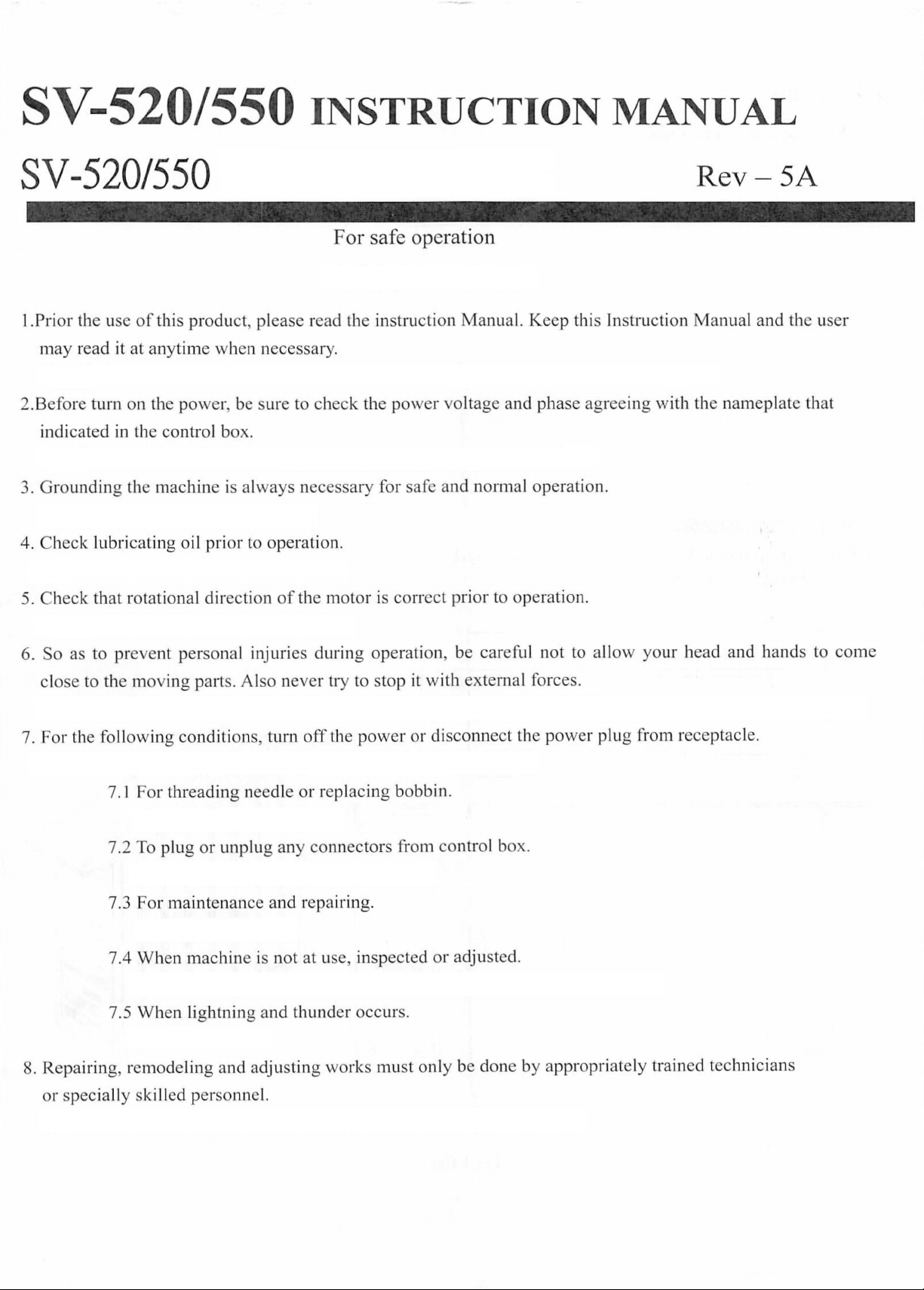
I.
Set
up
1.For
Dimensions
control
of
box
control
set
up
GTJ
r
box
as shown in Fig. I
lit
J~
-~
@
~
_J
c::=c::=-
---=:J
---=:J
H
301.05
290.75
301.6
328.77
235
- r
-
,
J
"1
7
~
~
=1 -'-
10.25
~1
'-
',;,
{s
I
~
I $n o $1
0 0
en
@ = @
0 0
D
[]
JJ~
t'i
~
Fig.I
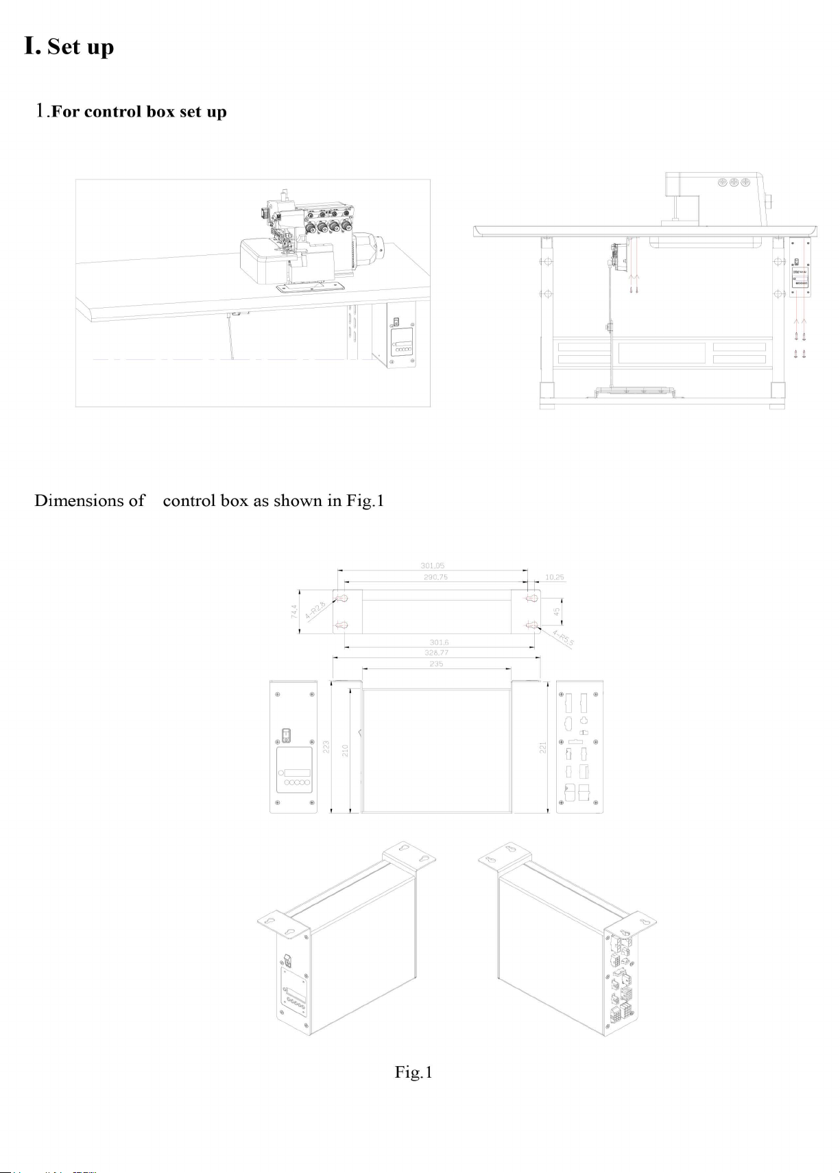
I. Set up
I .For motor & control box set up
Dimensions
of
motor & control box as shown in Fig. I
330
•••••
300.5
(".)
<O
C\J
""'"
If)
C'\i
cO
8
0
0
D
0
()
fl
D
DO
CJ
@
e
Fig.I
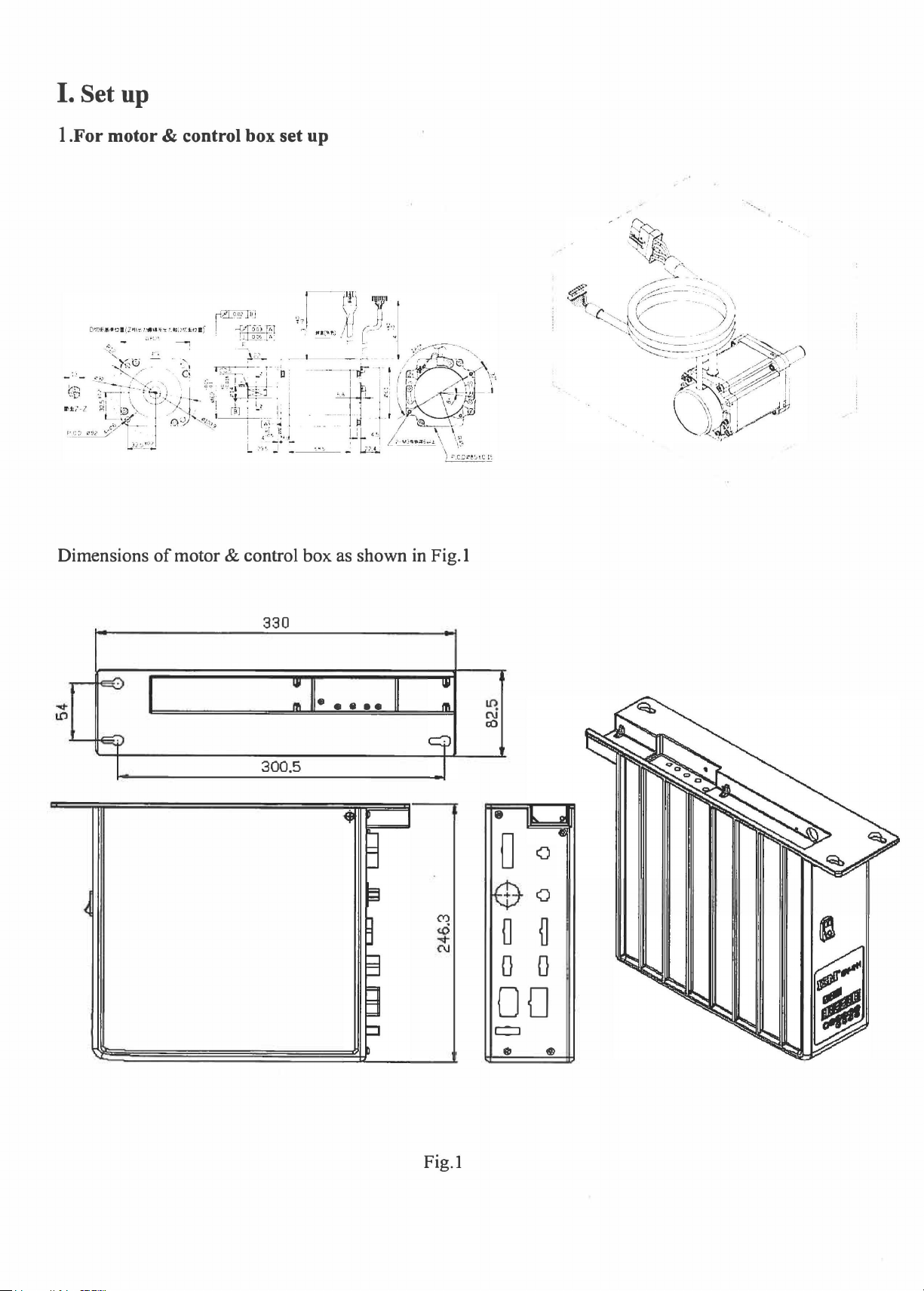
2.
Connector position and function
Circuit boards as Fig. 2 . Table 1 is the explanation for the connectors. Connectors for control box external
output please refer to Fig 3, then according to the machine, connect it to the respective connectors.
-)
CK2~
••
••
••
••
CN3
::
••
••
•
Connector
CN3
CNS
CN4
Fig.2
Option IN_I: pin 5
Option
Option IN_B : pin 9
Option IN_C : pin
IN_A:
pin 7 & 8
• m
CH5~
CN6~
CN
CNS~
7
:
:
rn
ctUJ~
CN
DUI~
CN
l6
9 e •
•
Connectors ' description
CO2
Front cover
Motor encoder connector
Standing operation pedal connector
& 6
&
10
11 & 12
connector
m
.
e e
[;}
..
••
• •
• •
••
CN13
CN14
CN7
CN6
External Panel connector
Speed unit connector
Safety switch connector
Synchronizer connector

CN9
CNll
CN16
CN15
Machine functions' connector
Option
Option
Option
Option
Foot lifter switch
Back tack switch
OPTION D connector
Option
Option
Option
OUT_B:
OUT_E:
OUT_F:
OUT_G:
IN_K: pin 2 & 6
IN_L:
IN M : pin 4 & 6
pin 6 &
pin 2 & 9
pin 1 & 8
pin 7 &
: pin 4 &
:pin5&12
Foot lifter Solenoid connector
pin 3 & 6
Material edge sensor connector
11
13
14
1---i~
3--~--r
0
CNS
CN12
Foot lifter discharge resistor
+12V Power output connector
Table 1
0
1-
2--0{]
3--{]
i
4-osJJ
5---+--
0
Fig.3
See Fig. 3
I .Motor power line connector.
>------le---
0
10
4--0
I .Motor power line connector.
.JJ
1---------l-
0 0
Fig.4 ·
See Fig. 4
11
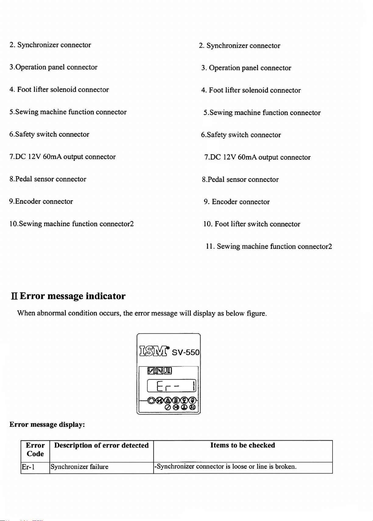
2. Synchronizer connector
2. Synchronizer connector
3.Operation panel connector
4. Foot lifter solenoid connector
5.Sewing machine function connector
6.Safety switch connector
7.DC 12V 60mA output connector
8.Pedal sensor connector
9.Encoder connector
10.Sewing machine function connector2
3. Operation panel connector
4. Foot lifter solenoid connector
5.Sewing machine function connector
6.Safety switch connector
7 .DC 12V 60mA output connector
8.Pedal sensor connector
9. Encoder connector
10
. Foot lifter switch connector
11.
Sewing machine function connector2
Il Error message indicator
When abnormal condition occurs, the error message will display as below figure.
~~Wsv-550
[ Er -
I]
Error message display:
Error Description
Code
Er-1
Synchronizer failure
of
error detected
-Synchronizer connector
Items to be checked
is
loose
or
line
is
broken.
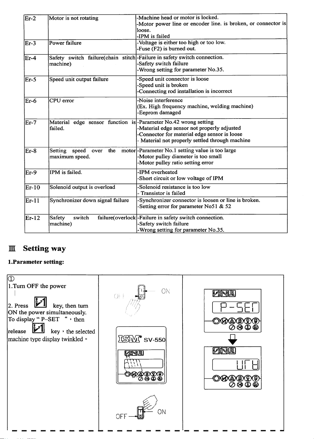
Er-2
Er-3
Motor
Power
is
not
failure
rotating
-Machine
-Motor
loose.
-IPM
-Voltage is
-Fuse
power
is failed
(F2)
head
either
is
burned
or
line
motor
or
too
high
out.
is locked.
encoder
or
too
line. is
low.
broken,
or
connector
is
Er-4
Er-5
Er-6
Er-7
Er-8
Er-9
Er-10
Er-11
Safety
machine)
Speed
CPU
Material
failed.
Setting
maximum
1PM is failed. -IPM
Solenoid
Synchronizer
switch
unit
error
speed
output
failure( chain stitch
output
edge
speed.
failure
sensor
over
is
down
overload
signal failure
function
the
-Failure in safety
-Safety
-Wrong
-Speed
-Speed
-Connecting
-Noise
(Ex.
-Eeprom
-Parameter
is
-Material
-Connector
Material
-
motor
-Parameter
-Motor
-Motor
-Short
-Solenoid
- Transistor is failed
-Synchronizer
-Setting
switch
setting
unit
connector
unit
is
rod installation is incorrect
interference
High
frequency
damaged
No.42
edge
for material
not
No.
pulley
pulley
overheated
circuit
resistance is too
error
switch
failure
for
parameter
is loose
broken
machine,
wrong
sensor
properly
I setting
diameter
ratio setting
or
connector
for
not
edge
settled
value
is
low
voltage
parameter
connection.
No.35.
welding
setting
properly
sensor
through
is
too
too
small
error
of
1PM
low
is loosen
No5
or
l &
machine)
adjusted
is loose
machine
large
line is broken.
52
Er-12
ill Setting
I.Parameter
Safety
machine)
way
setting:
CD
I.
Tum
OFF the
I
2. Press
ON
the power simultaneously.
lv11
To display
release
machine
IWI
type display twinkled
power
key, then
..
P-SET
key , the selected
switch
tum
" , then
0
failure(
overlock
CJ
I I
~~~SV-550
-Failure in safety
-Safety
-Wrong
.
-Gt
1///
/ ' i /·-...
i ( i
/
switch
setting for
-
Of\j
switch
failure
parameter
connection.
No.35.
OFF
PON
----------------------------
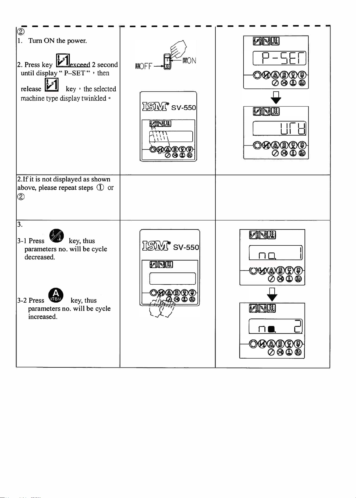
®
I. Turn
ON
the power.
2. Press key
until display
release
machine type display twinkled
2.lf
it
is
above, please repeat steps
0exceed
"
P-SET"
[1/1]
not displayed as shown
key , the selected
2 second
' then
®
3.
CD
0
~~~SV-550
or
Pres~ • key, thus
3-1
parameters no. will
decreased.
3-2 Press
parameters no. will be cycle
increased.
• key, thus
be
cycle
il~SV-550
101B[J]
[
(
no
na
I]
2)
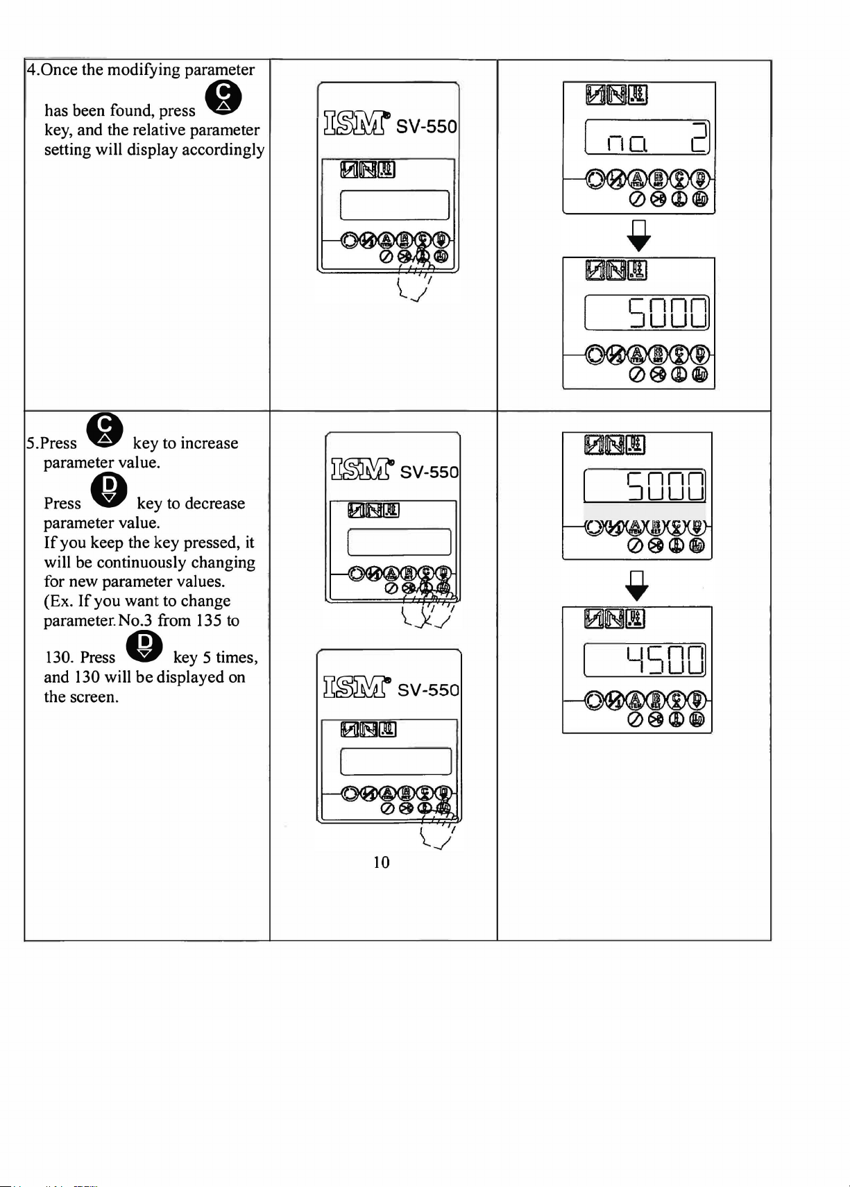
4.Once
the modifying parameter
has been found, press •
key, and the relative parameter
setting will display accordingly
~~SV-550
2)
101ms![IJ
5.Press • key to increase
parameter value.
Press
parameter value.
If
will be continuously changing
for new parameter values.
(Ex.
parameter.No.3 from 135 to
130. Press
and 130 will
the screen.
• key to decrease
you keep the key pressed,
If
you
want to change
O key 5 times,
be
displayed on
it
D~sv-sso
ims!~
~~SV-550
[
(
[
5000)
50001
'~SOD]
0~111
10
 Loading...