

Page 1

FLEXI PRO Servo Drive
Quick Start Guide
120/240 VAC and 400/480 VAC
Revision 8.1
Firmware Version 1.41.2
DOC-FLEXI PRO-QSG-EN
Page 2

FLEXI PRO
2 Quick Start Guide
Page 3
FLEXI PRO
Quick Start Guide 3
Revision History
Document
Revision
Date Remarks
8.1 May 2016 Added info and diagrams for EB models.
Minor revisions and corrections.
8.0 May 2016 Firmware 1.41.2
7.2 Mar.2015 Firmware 1.15.24
7.1/a/b/c Jan.2015 Updates and corrections.
7.0 Dec.2014 Firmware 1.15.xx
5.7 Jan.2014 Firmware 1.4.5
Firmware
Revision
Software (GUI)
Revision
1.41.2 1.41.2
Note: If an earlier firmware revision is installed in your FLEXI PRO drive,
contact your Account Manager or Technical Support.
Copyright Notice
© 2016 Motor Power Company s.r.l.
All rights reserved. No part of this work may be reproduced or transmitted in any
form or by any means without prior written permission of Motor Power Company.
Disclaimer
This product documentation was accurate and reliable at the time of its release.
Motor Power Company s.r.l. reserves the right to change the specifications of the
product described in this manual without notice at any time.
Trademarks
All marks in this manual are the property of their respective owners.
Contact Information
Motor Power Company s.r.l.
Via Leonardo Da Vinci , 4
42024 Castelnovo Sotto
Reggio Emilia - Italia
Tel: +39 0522 682710
Fax: +39 0522 683552
Website: www.motorpowerco.com
Technical Support
If you need assistance with the installation and configuration of the FLEXI PRO
drive, contact Motor Power Company Technical Support: [email protected]
Page 4

FLEXI PRO
4 Quick Start Guide
Contents
1 Introduction ................................................................................................... 5
FLEXI PRO Models .............................................................................................. 5
Safety .............................................................................................................. 6
FLEXI PRO Installation Procedure ......................................................................... 6
2 Wiring ............................................................................................................ 7
FLEXI PRO System Wiring ................................................................................... 7
FLEXI PRO Shielding and Bonding ........................................................................ 9
FLEXI PRO Grounding ....................................................................................... 10
FLEXI PRO Pin Assignments ............................................................................... 11
FLEXI PRO-1D5/FLEXI PRO-003 (120/240 VAC) ............................................... 11
FLEXI PRO-4D5/FLEXI PRO-006 (120/240 VAC) ............................................... 13
FLEXI PRO-008/FLEXI PRO-010/FLEXI PRO-013 (120/240 VAC) ......................... 15
FLEXI PRO-020/FLEXI PRO-024 (120/240 VAC) ................................................ 17
FLEXI PRO-003/FLEXI PRO-006 (400/480 VAC) ................................................ 19
FLEXI PRO-012 (400/480 VAC) ...................................................................... 21
Pin Assignments on FLEXI PRO-012 – AP/AF/EC Models .................................... 21
FLEXI PRO-024/FLEXI PRO-030 (400/480 VAC) ................................................ 23
3 Control Board ............................................................................................... 25
Overview ........................................................................................................ 25
Controller Interface .......................................................................................... 25
Controller Interface Wiring ............................................................................ 29
Machine Interface ............................................................................................ 31
Machine Interface Wiring ............................................................................... 32
Motor Feedback ............................................................................................... 34
Feedback Wiring .......................................................................................... 35
Fieldbus Devices .............................................................................................. 38
Host Computer ................................................................................................ 38
Daisy Chain ..................................................................................................... 39
Drive Address Switches ..................................................................................... 39
4 Power Board 120/240 VAC ........................................................................... 40
Safe Torque Off (STO) ...................................................................................... 40
Motor ............................................................................................................. 40
Regeneration Resistor ....................................................................................... 41
AC Input ......................................................................................................... 41
5 Power Board 400/480 VAC ........................................................................... 43
Safe Torque Off (STO) ...................................................................................... 43
Logic Power 24V Input ...................................................................................... 43
AC Input and Regeneration Resistor ................................................................... 44
Brake ............................................................................................................. 44
Motor ............................................................................................................. 44
6 Software ....................................................................................................... 45
Flexi SUITE Installation ..................................................................................... 45
Power Up ........................................................................................................ 45
Drive Configuration .......................................................................................... 45
7 Drive Status (7-Segment Display) ................................................................ 46
Page 5
FLEXI PRO
Quick Start Guide 5
1 Introduction
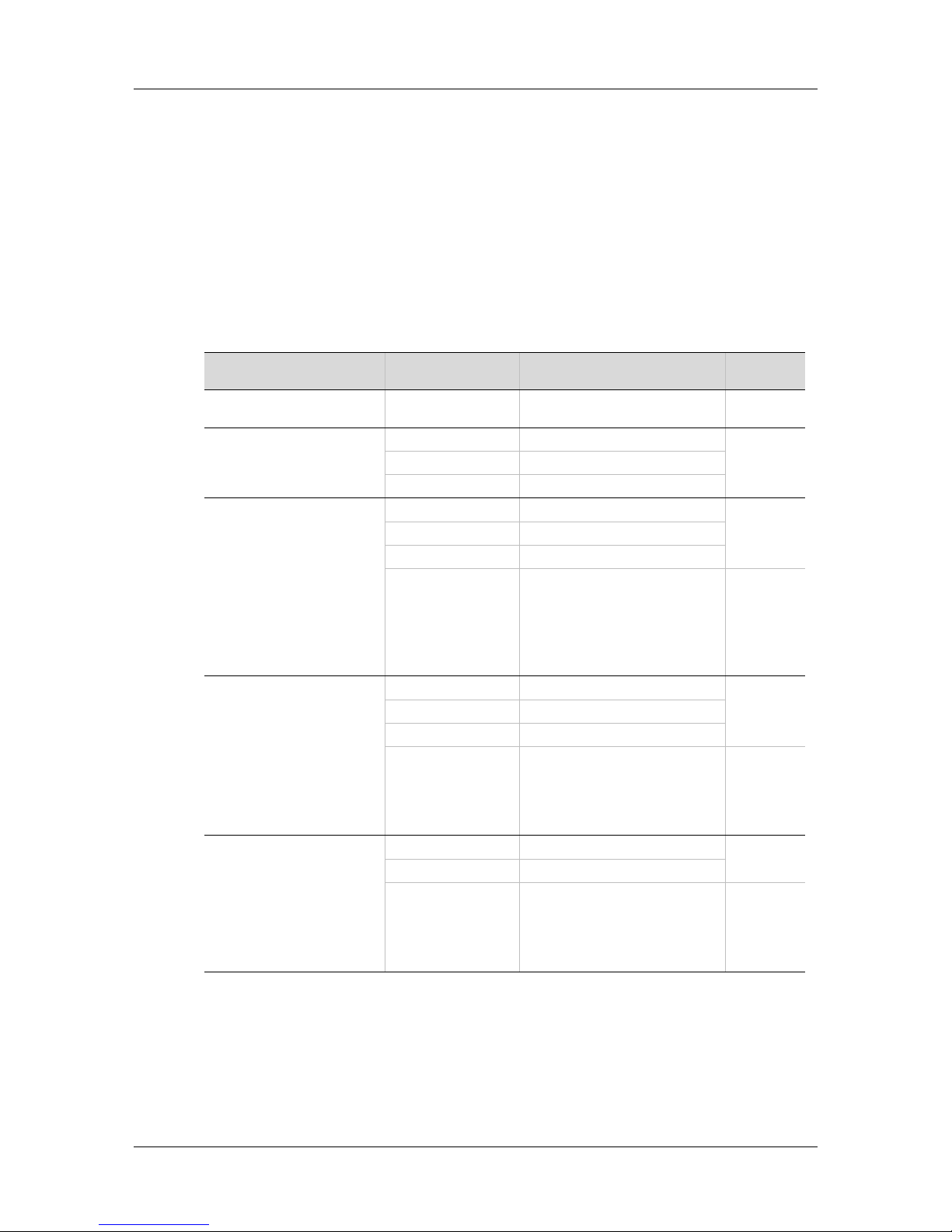
FLEXI PRO Models
The various models in the FLEXI PRO servo drive series are differentiated by means
of the communication methods and protocols they use. The following table
presents the different models and their distinguishing characteristics.
FLEXI PRO Models - Communication and Protocols
FLEXI PRO Model Physical Layer Communication Protocol Program
Language
FLEXI PRO Power Block (PB)* PWM signals PWM signals PMAC
(Delta Tau)
FLEXI PRO (AP)
Standard FLEXI PRO model.
Serial (RS232) ASCII commands VarCom
Analog ±10V
Pulse Train AB signals
FLEXI PRO CAN (AF)
A CAN drive, which uses
CANopen protocol.
Referred to as
FLEXI PRO CANopen drive.
Serial (USB|RS232) ASCII commands VarCom
Analog ±10V
Pulse Train AB signals
CAN Communication: CANopen
CANopen – all 1000h objects
Manufacturer-Specific:
CANopen – all 2000h objects
Standard Servo-Drive (Motion):
CANopen – all 6000h objects
VarCom
CANopen
FLEXI PRO EtherCAT (EC)
An EtherCAT drive, which
uses CANopen over
EtherCAT (CoE) protocol.
Serial (USB|RS232) ASCII commands VarCom
Analog ±10V
Pulse Train AB signals
Ethernet Communication: EtherCAT
Manufacturer-Specific:
CANopen – all 2000h objects
Standard Servo-Drive (Motion):
CANopen – all 6000h objects
VarCom
CANopen
FLEXI PRO EtherCAT
(EB)
An EtherCAT drive, which
uses CANopen over
EtherCAT (CoE) protocol
Serial (USB) ASCII commands VarCom
Analog ±10V
Ethernet Communication: EtherCAT
Manufacturer-Specific:
CANopen – all 2000h objects
Standard Servo-Drive (Motion):
CANopen – all 6000h objects
VarCom
CANopen
* Not included in this Quick Start Guide. Refer to the FLEXI PRO User Manual.
Page 6

FLEXI PRO
6 Quick Start Guide
Safety
Only qualified persons may perform the installation procedures. You do not need to
be an expert in motion control to install and operate the drive system. However,
you must have a basic understanding of electronics, computers, mechanics, and
safety practices.
The FLEXI PRO utilizes hazardous voltages.
Be sure the drive is properly grounded.
When connecting the FLEXI PRO to other control equipment, be sure to
follow two basic guidelines to prevent damage to the drive:
The FLEXI PRO must be grounded via the earth ground of the main
AC voltage supply.
Any motion controller, PLC or PC that is connected to the FLEXI PRO
must be grounded to the same earth ground as the FLEXI PRO.
Before you install the FLEXI PRO, review the safety instructions in the product
documentation. Failure to follow the safety instructions may result in personal
injury or equipment damage.
FLEXI PRO Installation Procedure
Perform the following steps to install and setup a FLEXI PRO system.
1. Mount the FLEXI PRO.
2. Make all electrical connections:
Controller I/Os and/or Machine I/Os
Motor feedback
Fieldbus devices, if required
Safe torque off (STO), or bypass using jumpers
Motor
Regeneration resistor, if required
Motor brake, if required
AC input voltage
3. Set the drive address using the rotary switches.
4. Connect the drive to the host computer.
5. Power up the drive and the computer.
6. Install Flexi SUITE software.
7. Using Flexi SUITE, configure and test the drive.
Page 7

FLEXI PRO
Quick Start Guide 7
2 Wiring
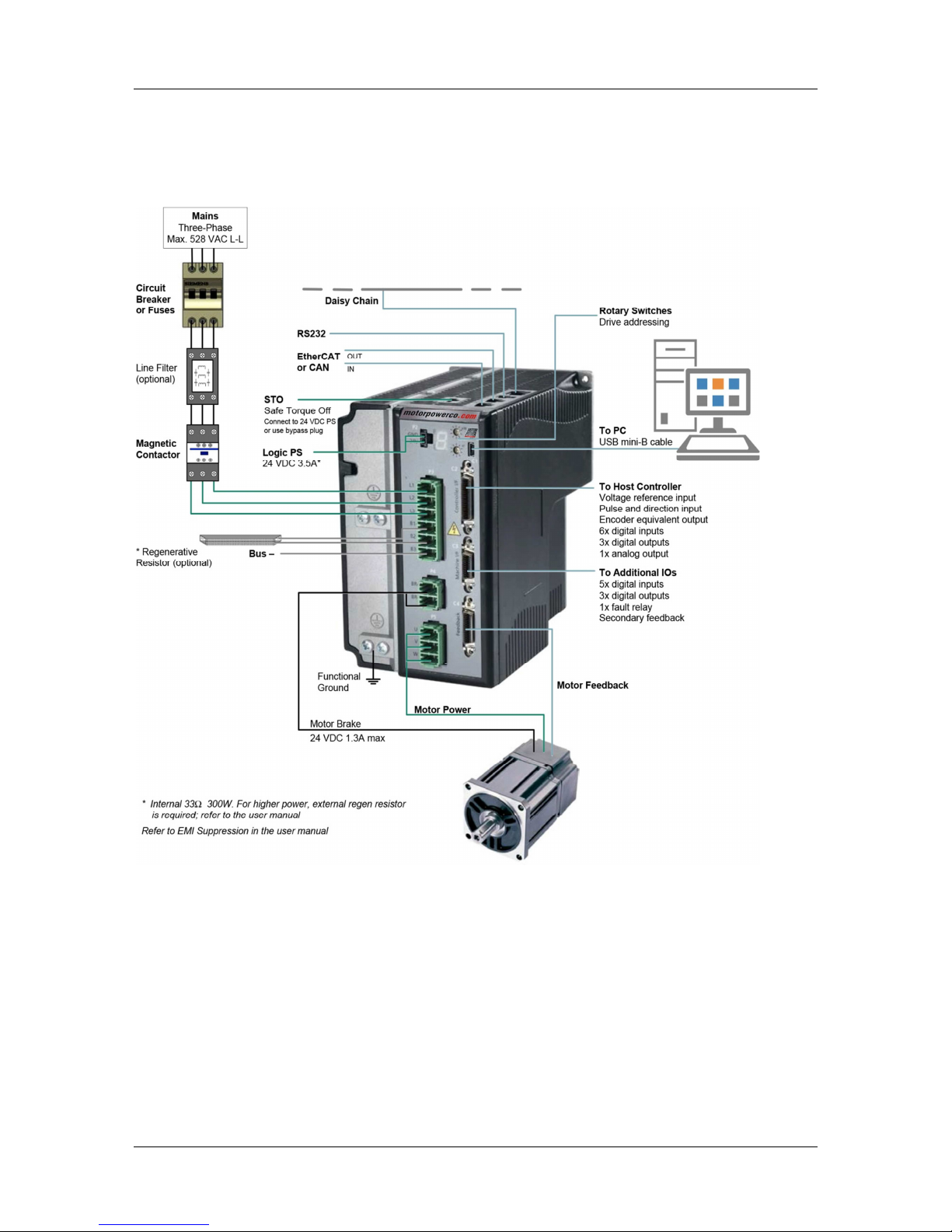
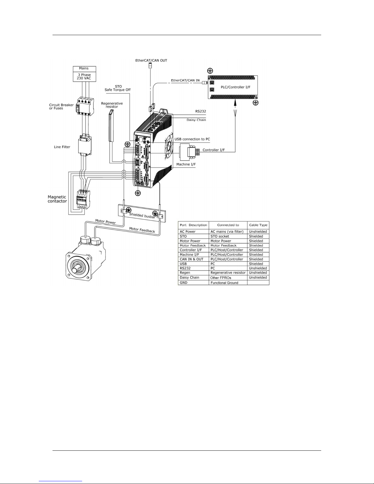
FLEXI PRO System Wiring
Example of Servo System Wiring, (120/240 VAC) 1-Phase
Page 8
FLEXI PRO
8 Quick Start Guide
Example of Servo System Wiring, (400/480 VAC) 3-Phase
Page 9
FLEXI PRO
Quick Start Guide 9
FLEXI PRO Shielding and Bonding
Page 10

FLEXI PRO
10 Quick Start Guide
FLEXI PRO Grounding
Page 11
FLEXI PRO
Quick Start Guide 11
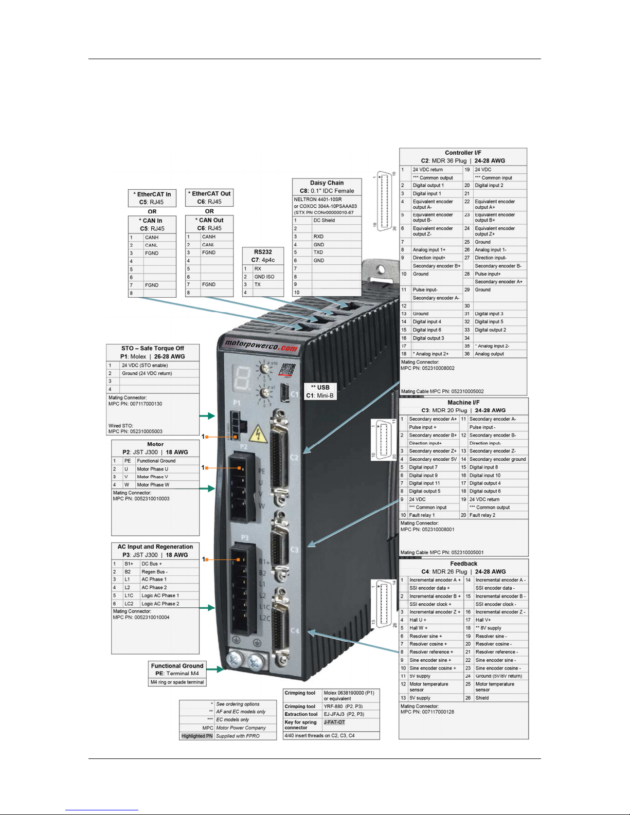
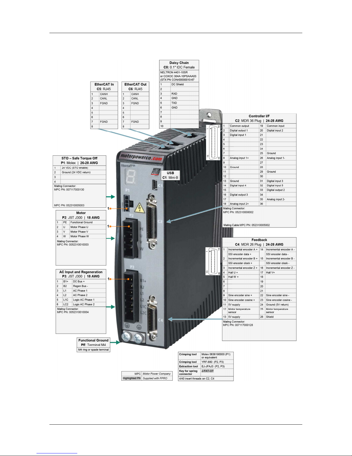
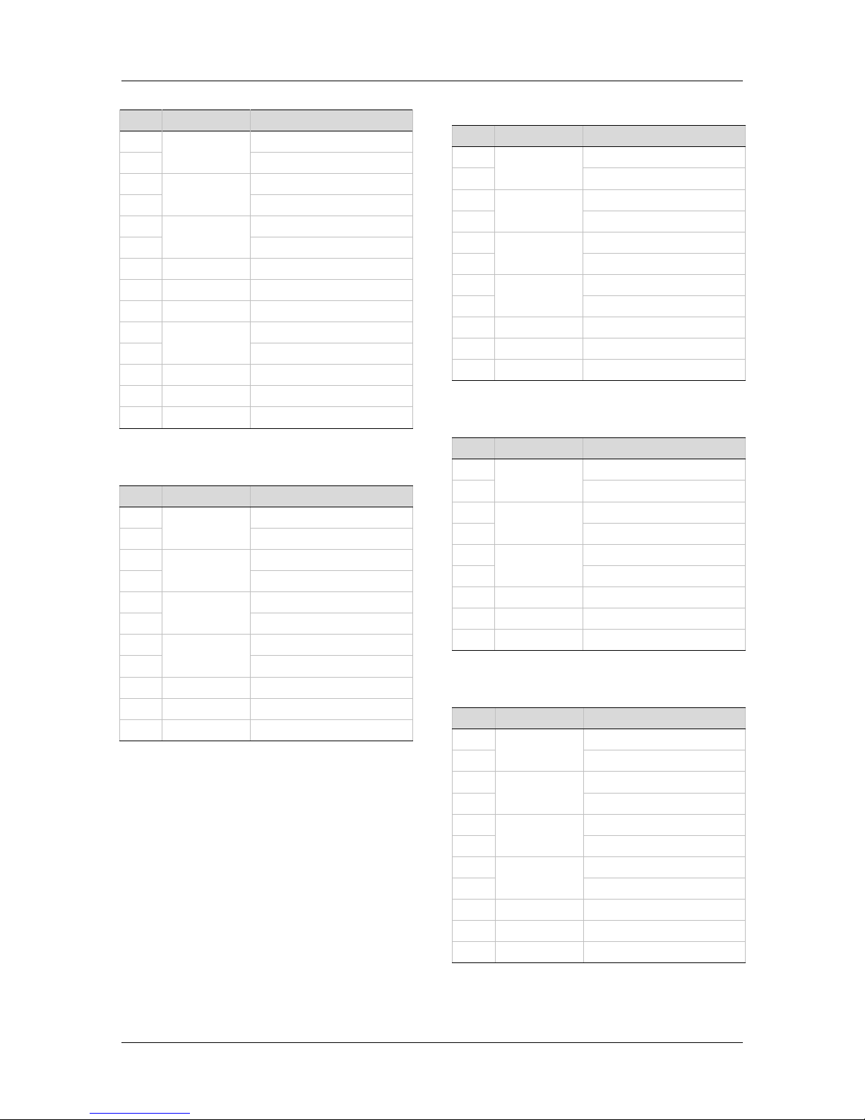
FLEXI PRO Pin Assignments
FLEXI PRO-1D5/FLEXI PRO-003 (120/240 VAC)
Pin Assignments on FLEXI PRO-1D5/FLEXI PRO-003 – AP/AF/EC Models
Page 12
FLEXI PRO
12 Quick Start Guide
Pin Assignments on FLEXI PRO-1D5/FLEXI PRO-003 – EB Models
Page 13

FLEXI PRO
Quick Start Guide 13
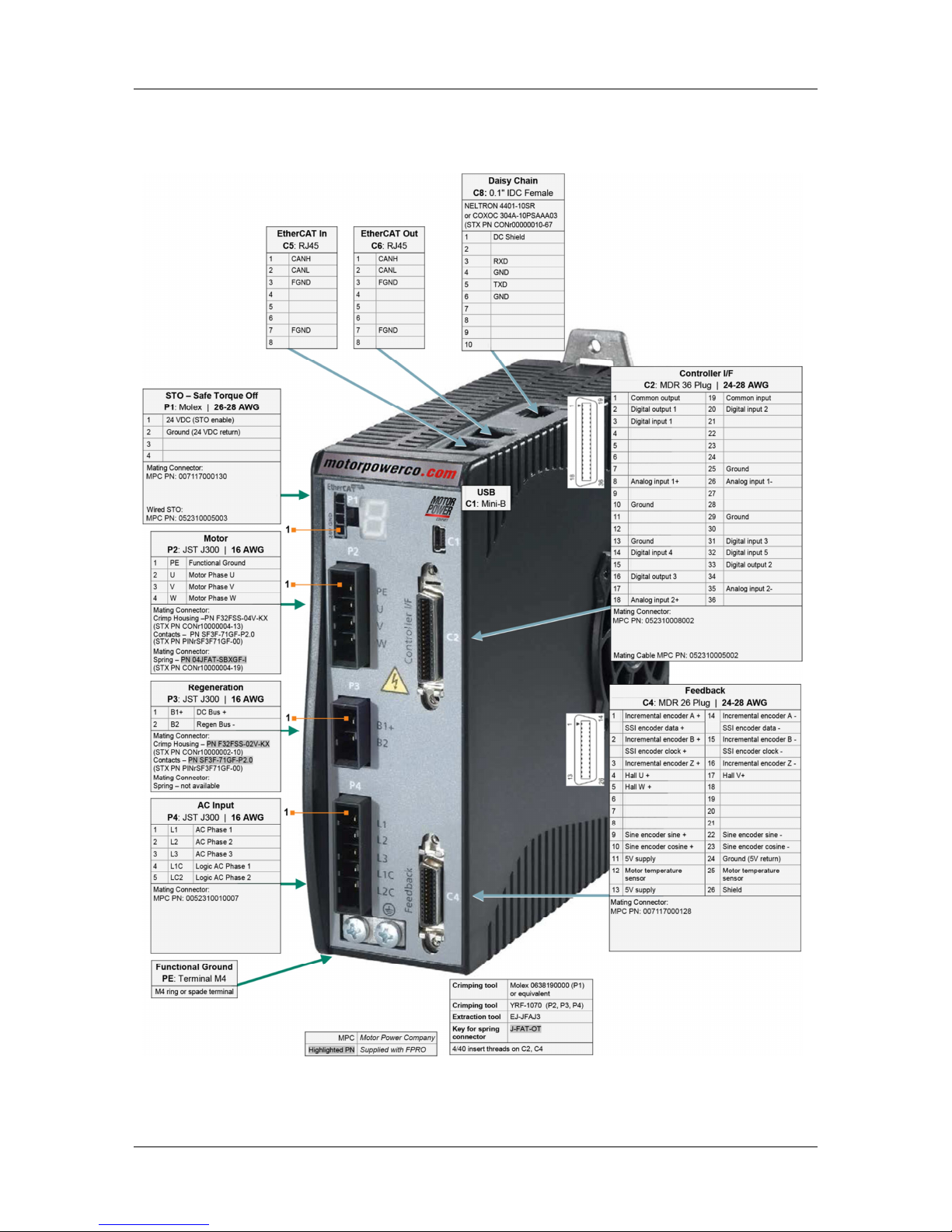
FLEXI PRO-4D5/FLEXI PRO-006 (120/240 VAC)
Pin Assignments on FLEXI PRO-4D5/FLEXI PRO-006 – AP/AF/EC Models
Page 14
FLEXI PRO
14 Quick Start Guide
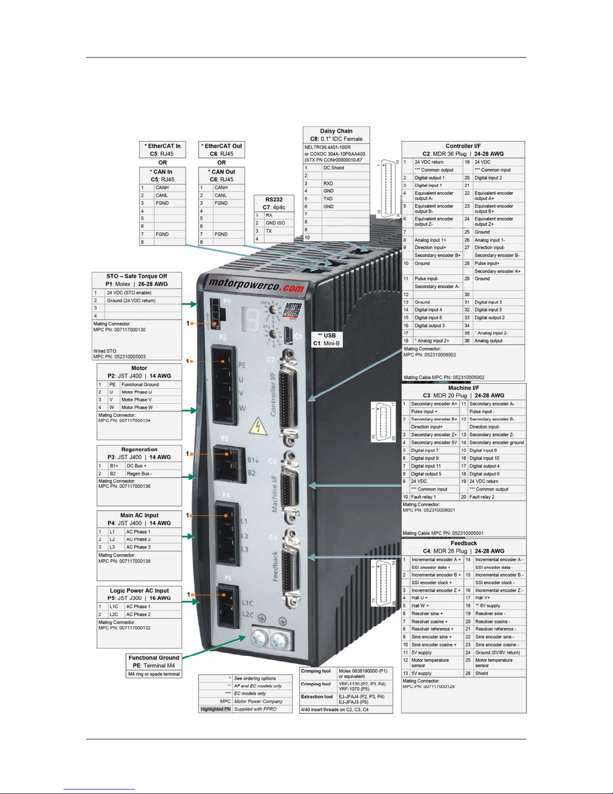
Pin Assignments on FLEXI PRO-4D5/FLEXI PRO-006 – EB Models
Page 15
FLEXI PRO
Quick Start Guide 15
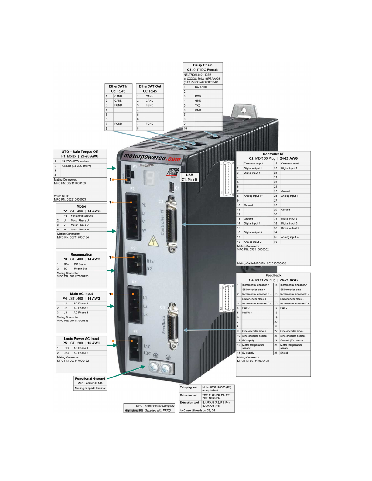
FLEXI PRO-008/FLEXI PRO-010/FLEXI PRO-013 (120/240 VAC)
Pin Assignments on FLEXI PRO-008/FLEXI PRO-010/FLEXI PRO-013 – AP/AF/EC Models
Page 16
FLEXI PRO
16 Quick Start Guide
Pin Assignments on FLEXI PRO-008/FLEXI PRO-010/FLEXI PRO-013 – EB Models
Page 17

FLEXI PRO
Quick Start Guide 17
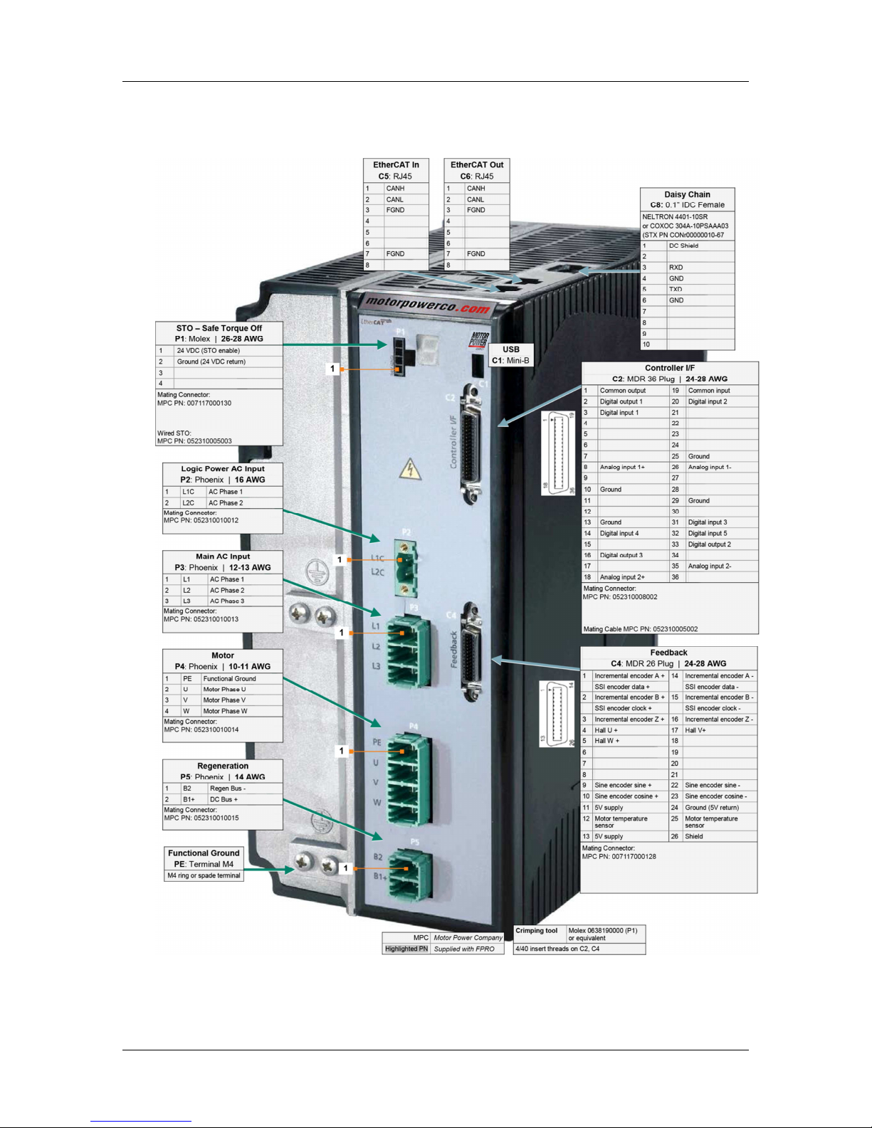
FLEXI PRO-020/FLEXI PRO-024 (120/240 VAC)
Pin Assignments on FLEXI PRO-020/FLEXI PRO-024 – AP/AF/EC Models
Page 18
FLEXI PRO
18 Quick Start Guide
Pin Assignments on FLEXI PRO-020/FLEXI PRO-024 – EB Models
Page 19
FLEXI PRO
Quick Start Guide 19
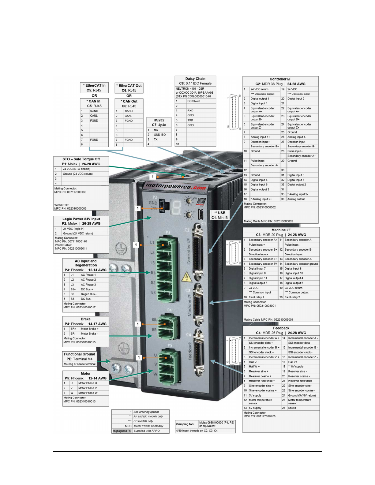
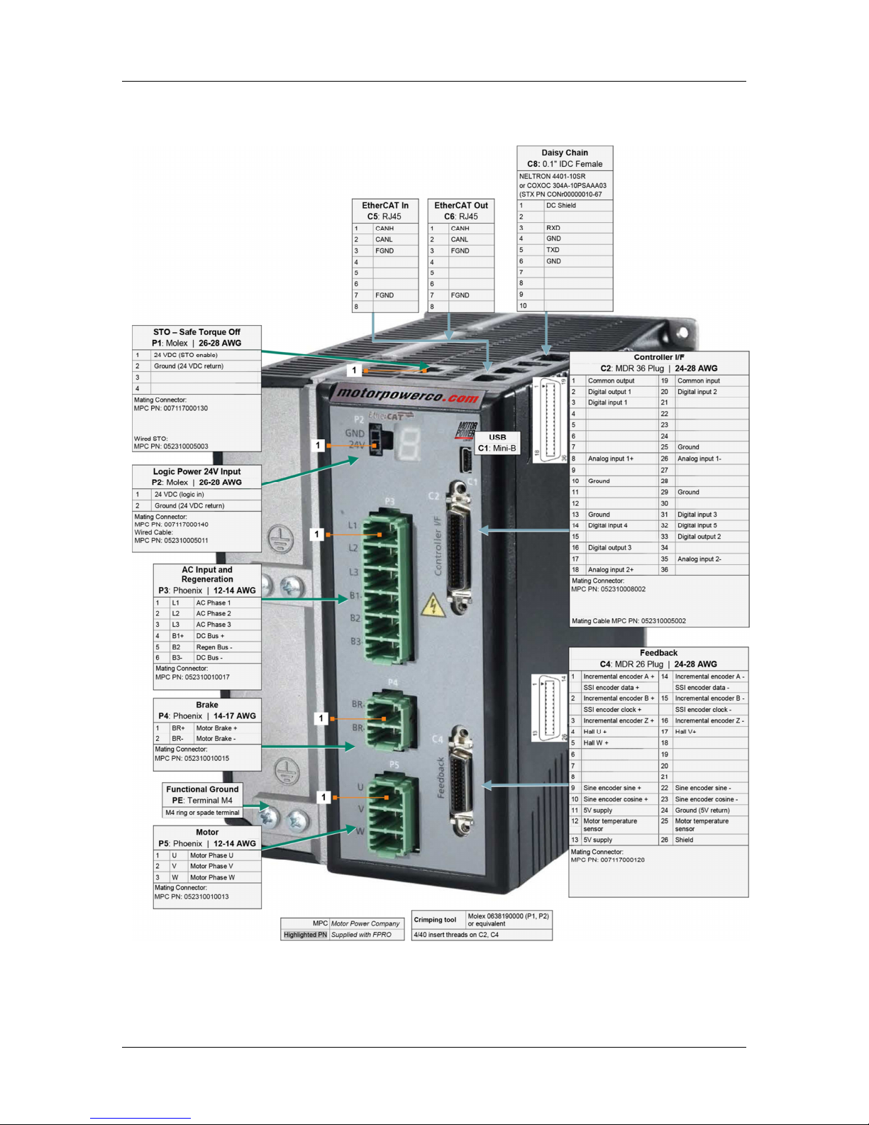
FLEXI PRO-003/FLEXI PRO-006 (400/480 VAC)
Pin Assignments on FLEXI PRO-003/FLEXI PRO-006 – AP/AF/EC Models
Page 20
FLEXI PRO
20 Quick Start Guide
Pin Assignments on FLEXI PRO-003/FLEXI PRO-006 – EB Models
Page 21
FLEXI PRO
Quick Start Guide 21
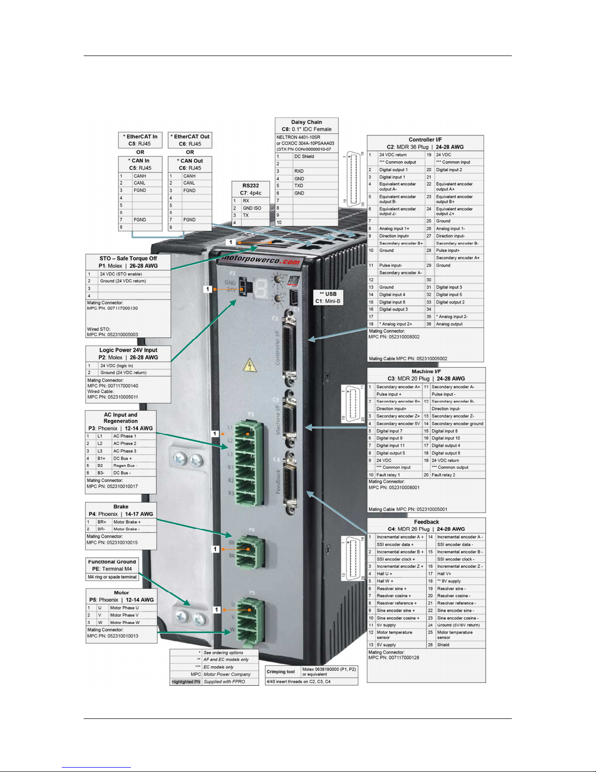
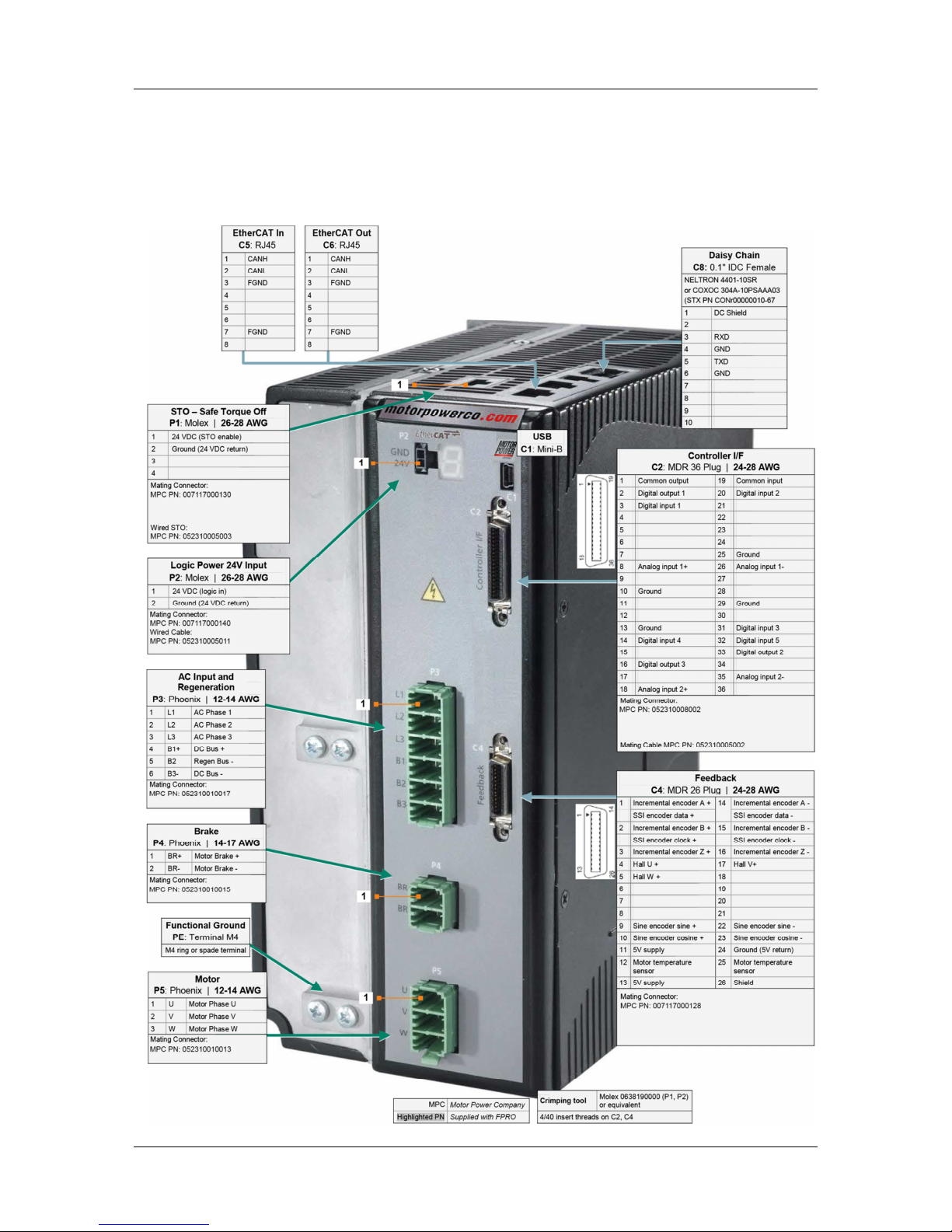
FLEXI PRO-012 (400/480 VAC)
Pin Assignments on FLEXI PRO-012 – AP/AF/EC Models
Page 22
FLEXI PRO
22 Quick Start Guide
Pin Assignments on FLEXI PRO-012 – EB Models
Page 23
FLEXI PRO
Quick Start Guide 23
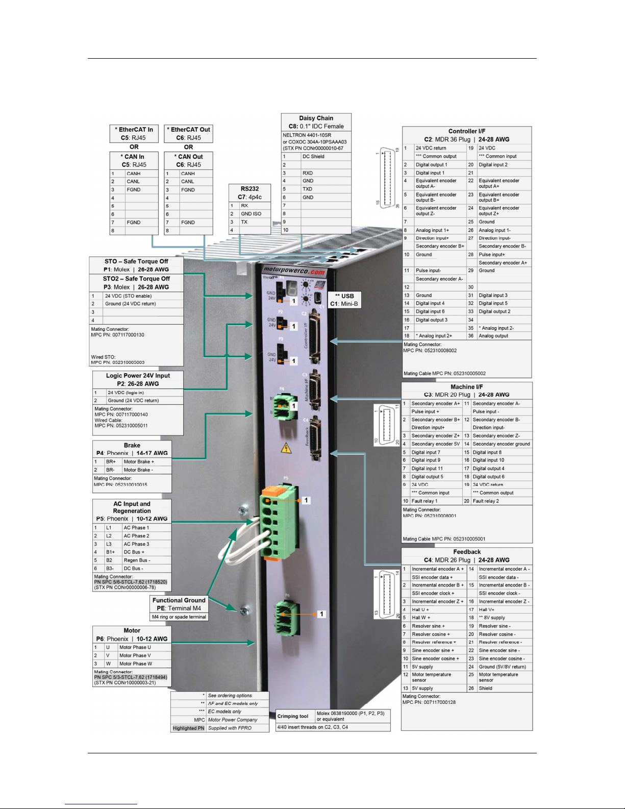
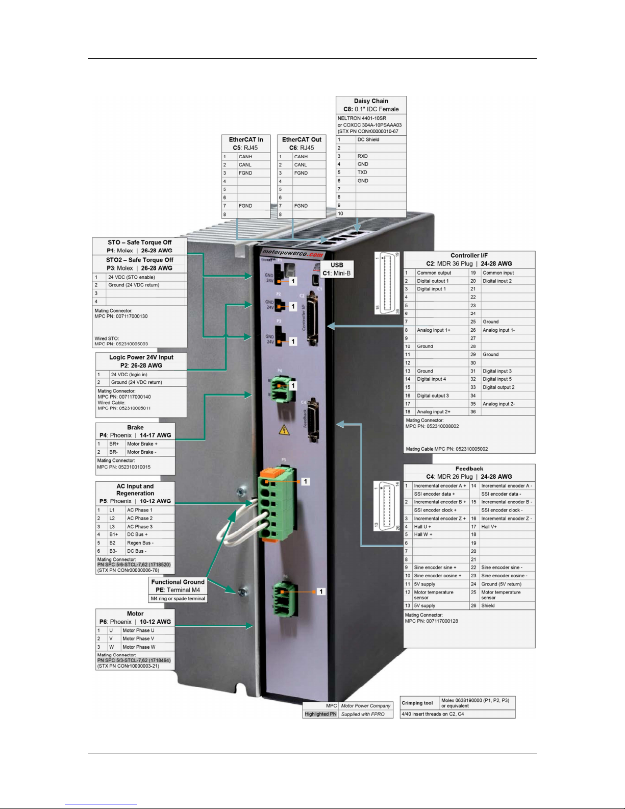
FLEXI PRO-024/FLEXI PRO-030 (400/480 VAC)
Pin Assignments on FLEXI PRO-024/FLEXI PRO-030 – AP/AF/EC Models
Page 24
FLEXI PRO
24 Quick Start Guide
Pin Assignments on FLEXI PRO-024/FLEXI PRO-030– EB Models
Page 25
FLEXI PRO
Quick Start Guide 25
3 Control Board
Overview
The control board interfaces vary depending on the specific FLEXI PRO model, as
detailed in the following table.
Control Board Interfaces
Function Interface AP AF EB EC
USB Communication C1 –
Controller Interface C2
Machine Interface C3
–
Motor Feedback C4
Fieldbus Devices C5 + C6 –
RS232 Communication C7
–
Daisy Chain C8
–
Drive Address RotarySwitches
–
Controller Interface
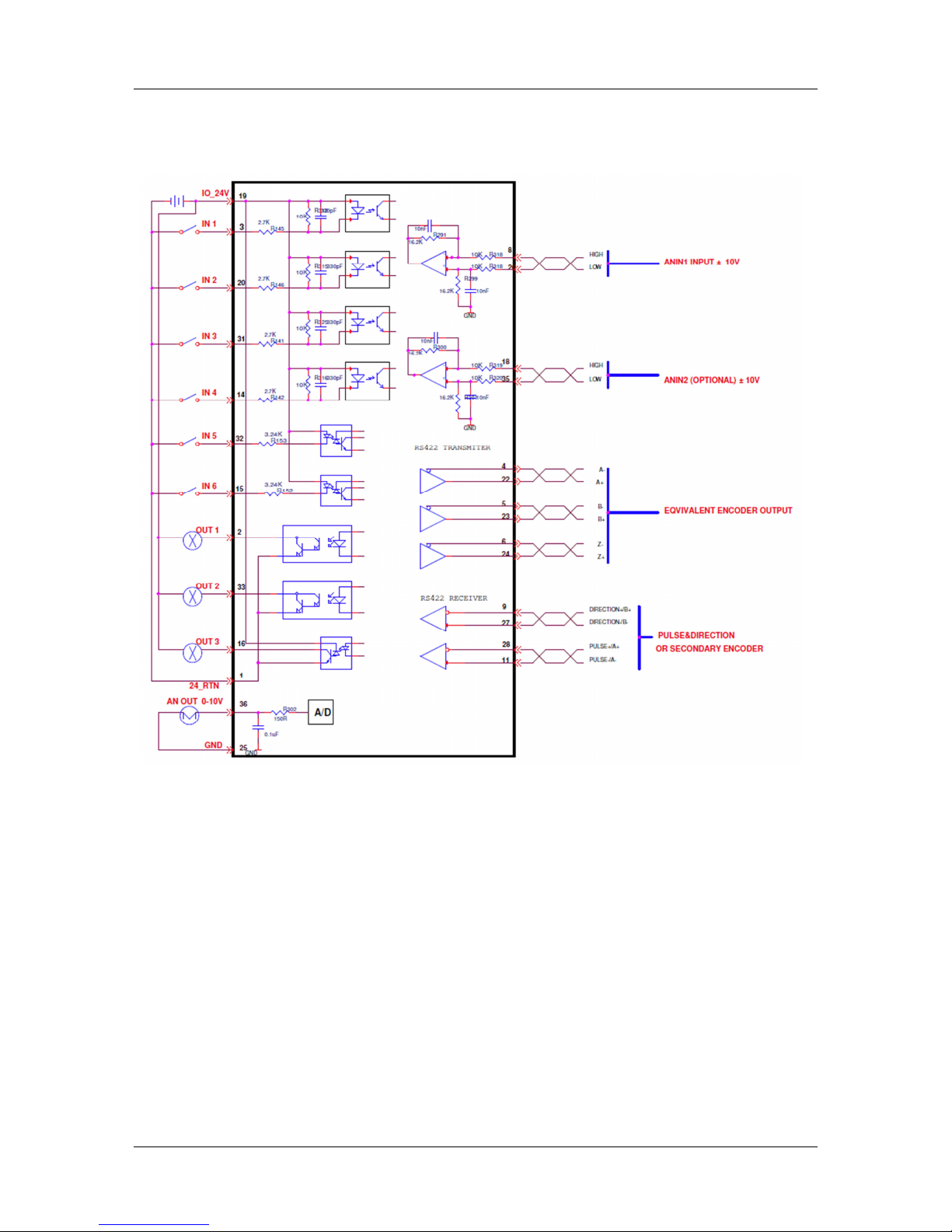
Wire the digital and analog inputs and outputs according to the requirements of
your application.
Unused pins must remain unwired.
AP/AF Models
Outputs are opto-isolated, and can be connected as sink only; outputs are
compatible with source inputs.
Inputs can be connected as source only; inputs are compatible with sink
outputs.
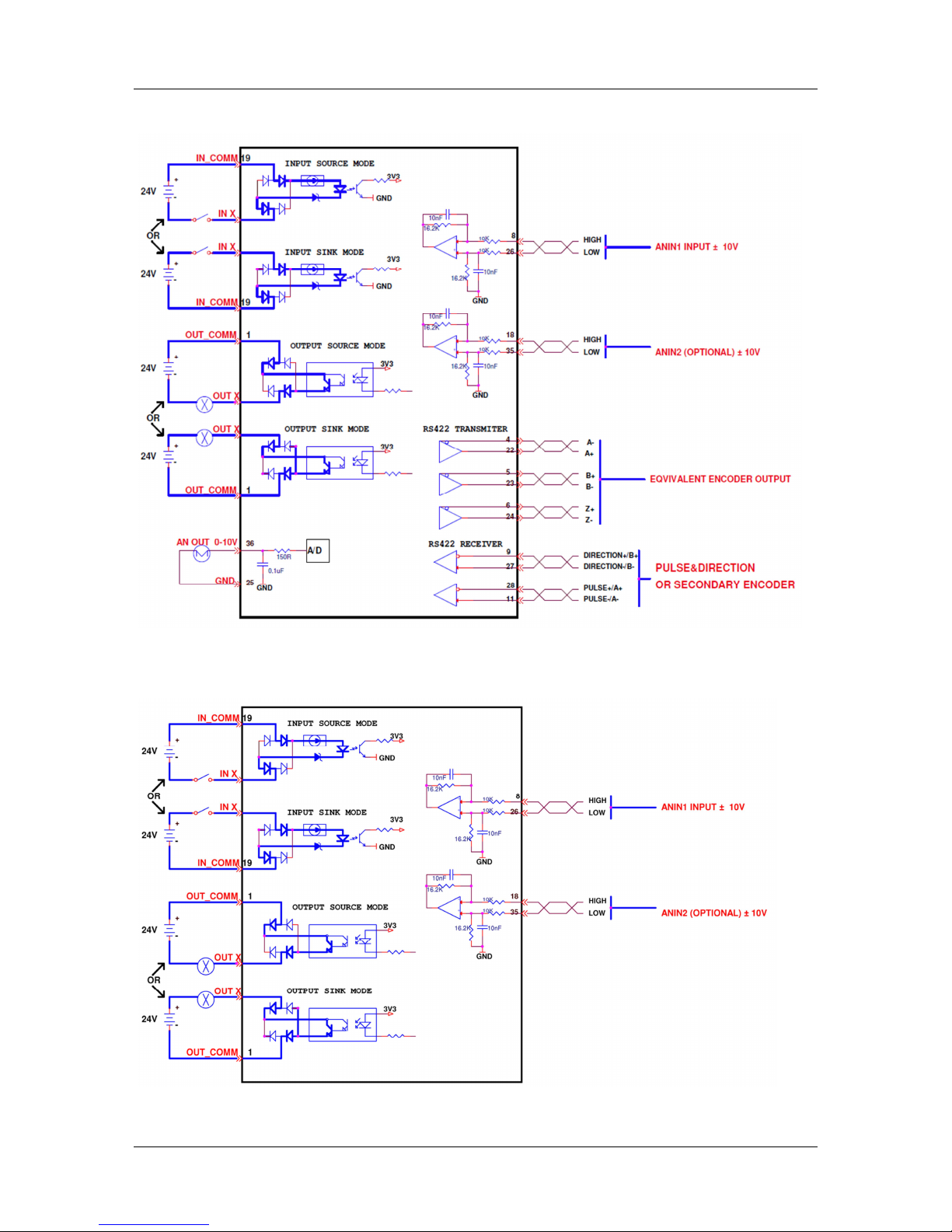
EC/EB Models
Outputs can be connected as either source or sink.
Inputs can be connected as either as source or sink.
Page 26
FLEXI PRO
26 Quick Start Guide
Controller Interface (C2) – AP/AF Models
Pin Function Description Pin Function Description
1 24 VDC return Return of the user-supplied
24 VDC
19 24 VDC User supplied 24V, for I/O biasing
2 Digital output 1 Opto-isolated programmable
digital output. Read using OUT1
20 Digital input 2 Opto-isolated programmable
digital input. Read using IN2
3 Digital input 1 Opto-isolated programmable
digital input. Read using IN1
21
4 Equivalent
encoder output
A-
Low side of the equivalent
encoder output signal A (RS422)
22 Equivalent
encoder output
A+
High side of the equivalent
encoder output signal A (RS422)
5 Equivalent
encoder output
B-
Low side of the equivalent
encoder output signal B (RS422)
23 Equivalent
encoder output
B+
High side of the equivalent
encoder output signal B (RS422)
6 Equivalent
encoder
output Z-
Low side of the equivalent
encoder output index (RS422)
24 Equivalent
encoder
output Z+
High side of the equivalent
encoder output index (RS422)
7 25 Ground Digital ground
8 Analog input 1+ High side of the differential
analog command input
(±10 VDC)
26 Analog input 1-
Low side of the differential analog
command input (±10 VDC)
9 Direction input+ High side of the direction signal
(RS422), or
High side of the down count
signal
27 Direction input- Low side of the direction signal
(RS422), or
Low side of the down count signal
Secondary
encoder B+
High side of the Secondary
encoder input signal B (RS422)
Secondary
encoder B-
Low side of the secondary
encoder input signal B (RS422)
10 Ground Digital ground 28 Pulse input+ High side of the pulse signal
(RS422), or
High side of the master encoder
signal A, or
High side of the up count signal
Secondary
encoder A+
High side of the secondary
encoder input signal A (RS422)
11 Pulse input- Low side of the pulse signal
(RS422), or
Low side of the master encoder
signal A, or
Low side of the up count signal
29 Ground Digital ground
Secondary
encoder A-
Low side of the secondary
encoder input signal A (RS422)
12 30
13 Ground Digital ground 31 Digital input 3 Opto-isolated programmable
digital input. Read using IN3
14 Digital input 4 Opto-isolated programmable
digital input. Read using IN4
32 Digital input 5 Fast opto-isolated programmable
digital input. Read using IN5
15 Digital input 6 Fast opto-
isolated programmable
digital input. Read using IN6
33 Digital output 2 Opto-isolated programmable
digital output. Read using OUT2
16 Digital output 3 Fast opto-
isolated programmable
digital output. Read using OUT3
34
17 35* Analog input 2-
Low side of the second differential
analog input (±10 VDC)
18* Analog input 2+ High side of the second
differential analog input
(±10 VDC)
36 Analog output Analog output, referenced to
digital ground (0-10 VDC)
* Optional, see ordering information. Blank cells indicate unused pins; these pins must remain unwired.
Page 27
FLEXI PRO
Quick Start Guide 27
Controller Interface (C2) – EC Model
Pin Function Description Pin Function Description
1 Common output 19 Common input
2 Digital output 1 Opto-isolated programmable
digital output. Read using OUT1
20 Digital input 2 Opto-isolated programmable
digital input. Read using IN2
3 Digital input 1 Opto-isolated programmable
digital input. Read using IN1
21
4 Equivalent
encoder output
A-
Low side of the equivalent
encoder output signal A (RS422)
22 Equivalent
encoder output
A+
High side of the equivalent
encoder output signal A (RS422)
5 Equivalent
encoder output
B-
Low side of the equivalent
encoder output signal B (RS422)
23 Equivalent
encoder output
B+
High side of the equivalent
encoder output signal B (RS422)
6 Equivalent
encoder
output Z-
Low side of the equivalent
encoder output index (RS422)
24 Equivalent
encoder
output Z+
High side of the equivalent
encoder output index (RS422)
7 25 Ground Digital ground
8 Analog input 1+ High side of the differential
analog command input
(±10 VDC)
26 Analog input 1-
Low side of the differential analog
command input (±10 VDC)
9 Direction input+ High side of the direction signal
(RS422), or
High side of the down count
signal
27 Direction input- Low side of the direction signal
(RS422), or
Low side of the down count signal
Secondary
encoder B+
High side of the Secondary
encoder input signal B (RS422)
Secondary
encoder B-
Low side of the secondary
encoder input signal B (RS422)
10 Ground Digital ground 28 Pulse input+ High side of the pulse signal
(RS422), or
High side of the master encoder
signal A, or
High side of the up count signal
Secondary
encoder A+
High side of the secondary
encoder input signal A (RS422)
11 Pulse input- Low side of the pulse signal
(RS422), or
Low side of the master encoder
signal A, or
Low side of the up count signal
29 Ground Digital ground
Secondary
encoder A-
Low side of the secondary
encoder input signal A (RS422)
12 30
13 Ground Digital ground 31 Digital input 3 Opto-isolated programmable
digital input. Read using IN3
14 Digital input 4 Opto-isolated programmable
digital input. Read using IN4
32 Digital input 5 Fast opto-isolated programmable
digital input. Read using IN5
15 Digital input 6 Fast opto-
isolated programmable
digital input. Read using IN6
33 Digital output 2 Opto-isolated programmable
digital output. Read using OUT2
16 Digital output 3 Fast opto-
isolated programmable
digital output. Read using OUT3
34
17 35* Analog input 2-
Low side of the second differential
analog input (±10 VDC)
18* Analog input 2+ High side of the second
differential analog input
(±10 VDC)
36 Analog output Analog output, referenced to
digital ground (0-10 VDC)
* Optional, see ordering information. Blank cells indicate unused pins; these pins must remain unwired.
Page 28
FLEXI PRO
28 Quick Start Guide
Controller Interface (C2) – EB Model
Pin Function Description Pin Function Description
1 Common output 19 Common input
2 Digital output 1 Opto-isolated programmable
digital output. Read using OUT1
20 Digital input 2 Opto-isolated programmable
digital input. Read using IN2
3 Digital input 1 Opto-isolated programmable
digital input. Read using IN1
21
4 22
5 23
6 24
7 25 Ground Digital ground
8 Analog input 1+ High side of the differential
analog command input
(±10 VDC)
26 Analog input 1- Low side of the differential analog
command input (±10 VDC)
9 27
10 Ground Digital ground 28
11 29 Ground Digital ground
12 30
13 Ground Digital ground 31 Digital input 3 Opto-isolated programmable
digital input. Read using IN3
14 Digital input 4 Opto-isolated programmable
digital input. Read using IN4
32 Digital input 5 Fast opto-isolated programmable
digital input. Read using IN5
33 Digital output 2 Opto-isolated programmable
digital output. Read using OUT2
16 Digital output 3 Opto-isolated programmable
digital output. Read using OUT3
34
17 35 Analog input 2- Low side of the second differential
analog input (±10 VDC)
18 Analog input 2+ High side of the second
differential analog input
(±10 VDC)
36
Blank cells indicate unused pins; these pins must remain unwired.
Page 29
FLEXI PRO
Quick Start Guide 29
Controller Interface Wiring
Controller Interface Wiring – AP/AF Models
Page 30
FLEXI PRO
30 Quick Start Guide
Controller Interface Wiring – EC Models
Controller Interface Wiring – EB Models
Page 31
FLEXI PRO
Quick Start Guide 31
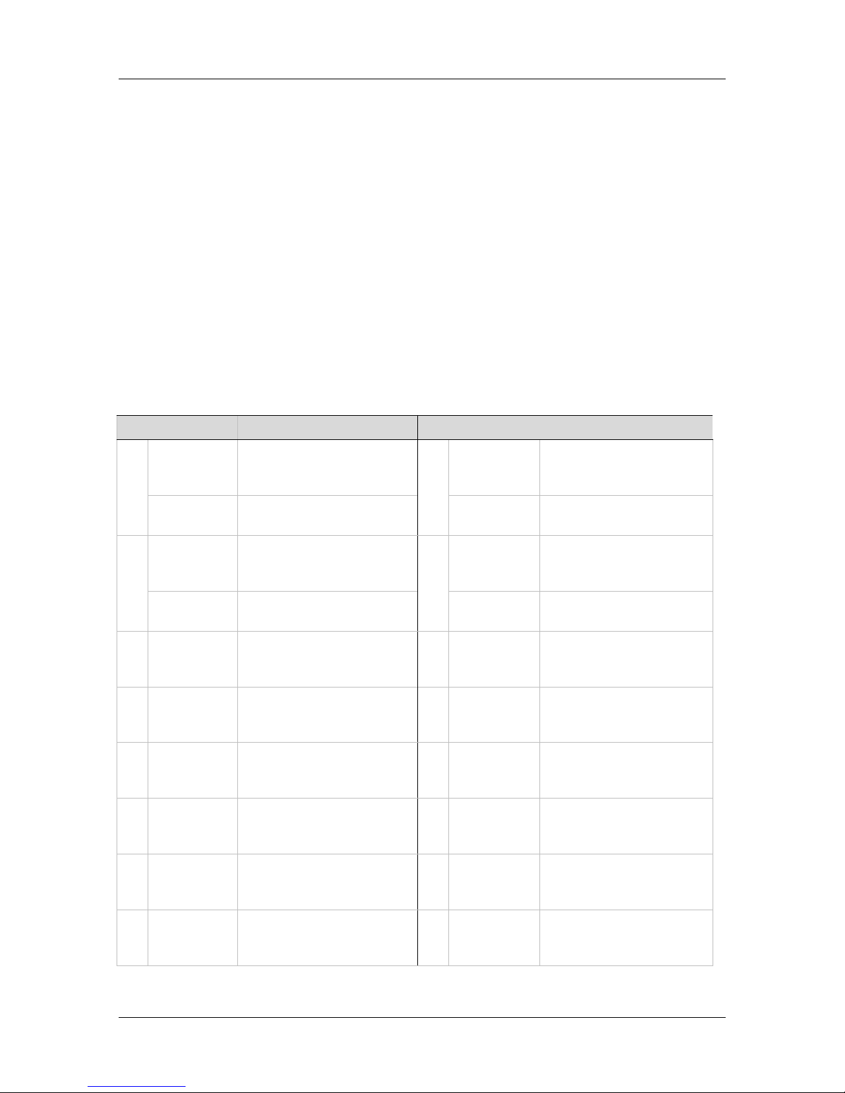
Machine Interface
Note: EB model does not have a Machine Interface.
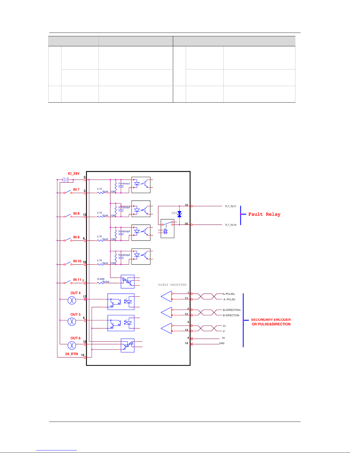
Wire the machine inputs and outputs according to the requirements of your
application.
AP/AF Models
Outputs are opto-isolated, and can be connected as sink only; outputs are
compatible with source inputs.
Inputs can be connected as source only; inputs are compatible with sink
outputs.
EC/EB Models
Outputs can be connected as either source or sink.
Inputs can be connected as either as source or sink.
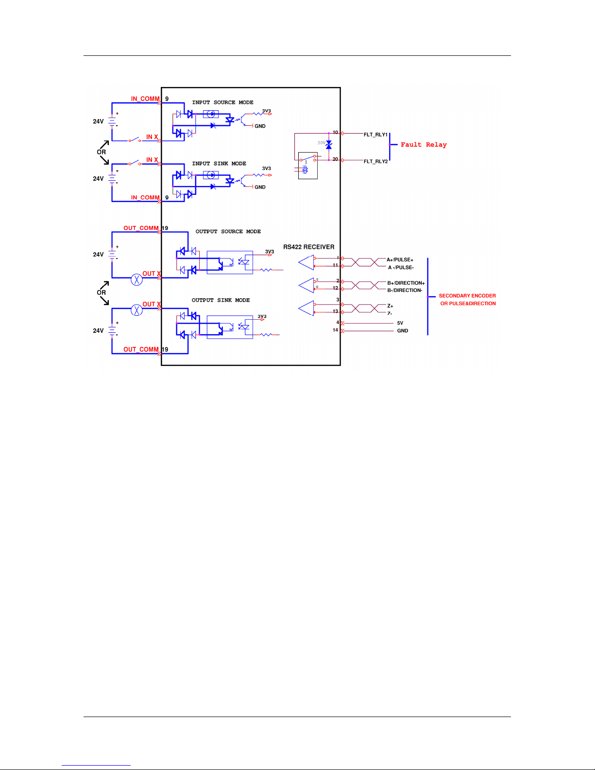
Machine Interface (C3)
Pin Function Description Pin Function Description
1 Secondary
encoder A+
High side of the
secondary encoder input
signal A (RS422)
11 Secondary
encoder A-
Low side of the
secondary encoder input
signal A (RS422)
Pulse input+ High side of the pulse
signal
Pulse input- Low side of the pulse
signal
2 Secondary
encoder B+
High side of the
Secondary encoder input
signal B (RS422)
12 Secondary
encoder B-
Low side of the
secondary encoder input
signal B (RS422)
Direction
input+
High side of the direction
signal
Direction
input-
Low side of the direction
signal
3 Secondary
encoder Z+
High side of the
secondary encoder input
index (RS422)
13 Secondary
encoder Z-
Low side of the
secondary encoder input
index (RS422)
4 Secondary
encoder 5V
5 VDC supply for the
secondary encoder
14 Secondary
encoder
ground
Ground of the 5 VDC
supply for the secondary
encoder.
5 Digital
input 7
Opto-isolated
programmable digital
input. Read using IN7
15 Digital
input 8
Opto-isolated
programmable digital
input. Read using IN8
6 Digital
input 9
Opto-isolated
programmable digital
input. Read using IN9
16 Digital
input 10
Opto-isolated
programmable digital
input. Read using IN10
7 Digital
input 11
Fast opto-isolated
programmable digital
input. Read using IN11
17 Digital
output 4
Opto-isolated
programmable digital
output. Read using OUT4
8 Digital
output 5
Opto-isolated
programmable digital
output. Read using OUT5
18 Digital
output 6
Fast opto-isolated
programmable digital
output. Read using OUT6
Page 32
FLEXI PRO
32 Quick Start Guide
Pin Function Description Pin Function Description
9 24 VDC AP/AF Models: User
supplied 24V, for I/O
biasing
19 24 VDC
return
AP/AF Models: Return
of the user-supplied
24 VDC
Common
input
EC Models Common
output
EC Models
10 Fault relay 1 Terminal 1 of the dry
contact fault relay
20 Fault relay 2 Terminal 2 of the dry
contact fault relay
Machine Interface Wiring
Machine Interface Wiring – AP/AF Models
Page 33
FLEXI PRO
Quick Start Guide 33
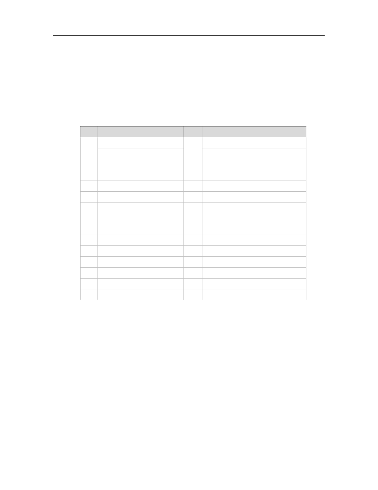
Machine Interface Wiring – EC Models
Page 34
FLEXI PRO
34 Quick Start Guide
Motor Feedback
Wire the motor feedback interface according to the type of feedback device to be
used in your application. Refer to the guidelines following the pinout table below.
Pins 1, 2, 14 and 15 have dual functionality.
Pin 25 for the motor temperature sensor is connected internally in the drive to
FLEXI PRO ground.
Unused pins must remain unwired.
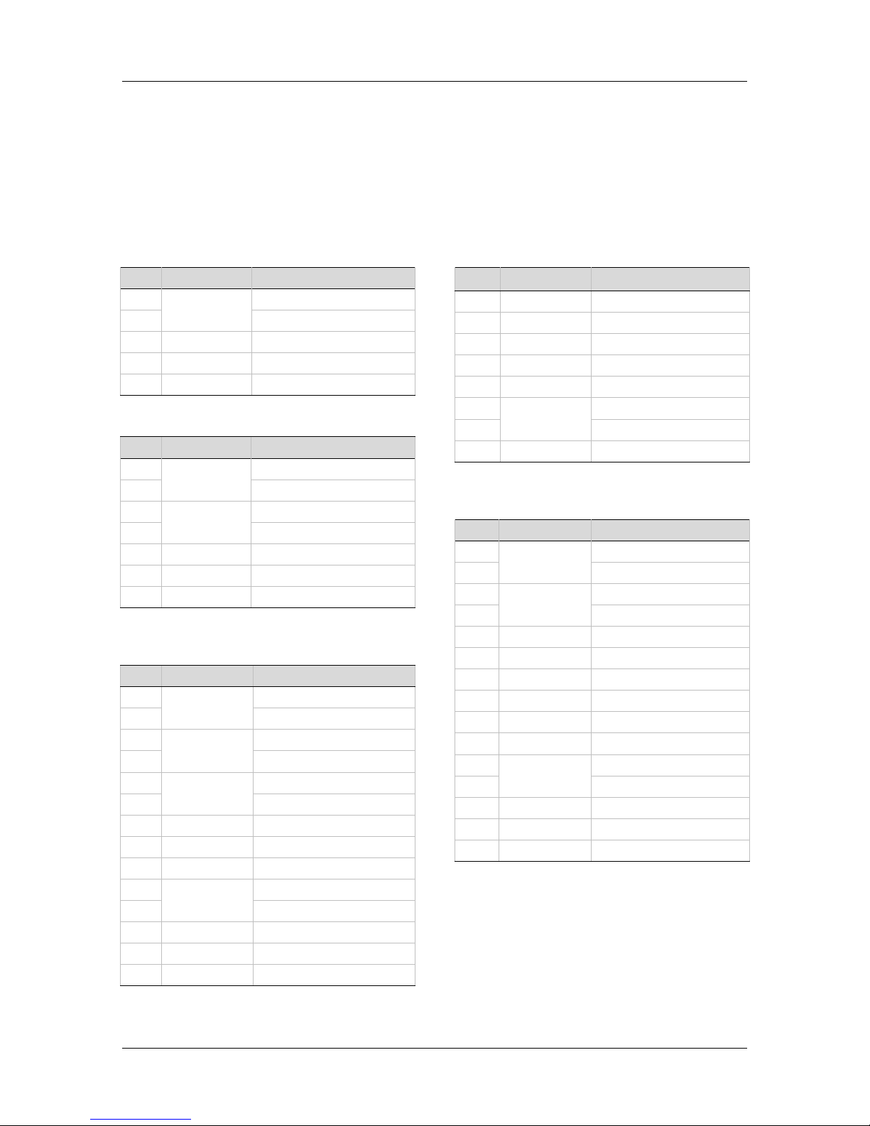
Motor Feedback Interface (C4)
Pin Function Pin Function
1 Incremental encoder A + 14 Incremental encoder A -
Serial encoder data + Serial encoder data -
2 Incremental encoder B + 15 Incremental encoder B -
Serial encoder clock + Serial encoder clock -
3 Incremental encoder Z + 16 Incremental encoder Z -
4 Hall U + 17 Hall V+
5 Hall W + 18 AF/EC Models: 8V supply
6 Resolver sine + 19 Resolver sine -
7 Resolver cosine + 20 Resolver cosine -
8 Resolver reference + 21 Resolver reference -
9 Sine encoder sine + 22 Sine encoder sine -
10 Sine encoder cosine + 23 Sine encoder cosine -
11 5V supply 24 Ground (5V/8V return)
12 Motor temperature sensor 25 Motor temperature sensor
13 5V supply 26 Shield
Page 35
FLEXI PRO
Quick Start Guide 35
Feedback Wiring
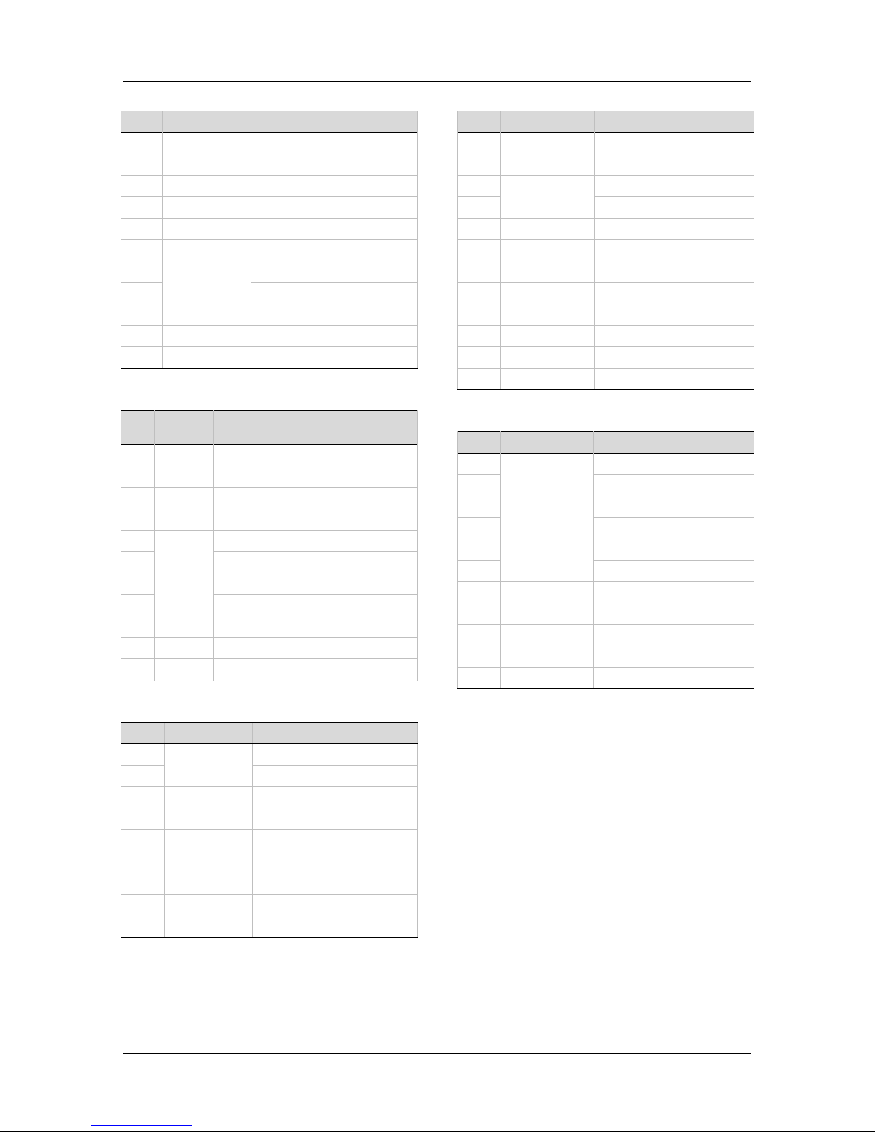
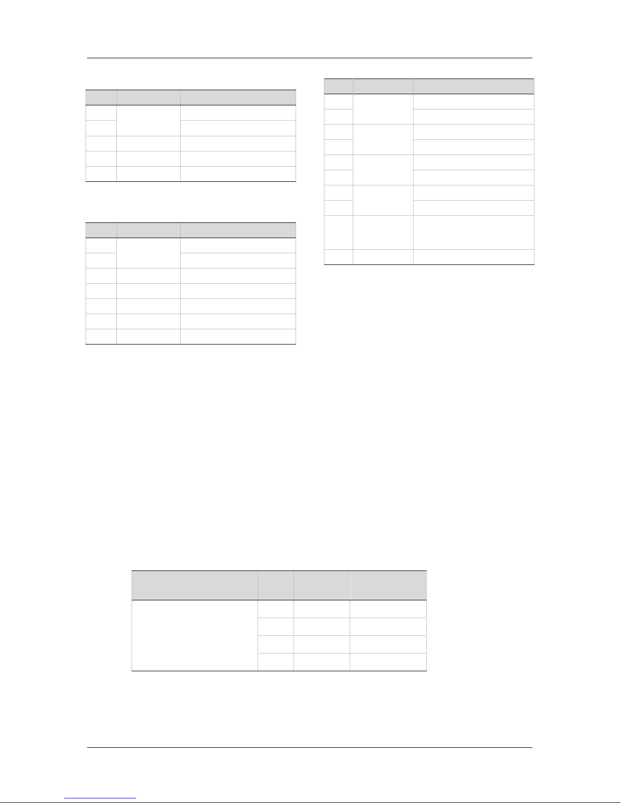
The following tables present suggestions for the most common feedback variations.
Refer to the drive’s User Manual for additional information. If your motor feedback
does not match any of the following, contact technical support.
Use the Flexi SUITE Motor Setup procedure and the Feedback screens to define
motor feedback type, resolution, and other parameters.
sensAR Encoder A
Pin # Twisted Pair Signal Description
1 Twisted Pair Serial Data +
14 Serial Data -
11 +5 VDC
24 0 VDC
26 Shield
BiSS-C Encoder
Pin # Twisted Pair Signal Description
1 Twisted Pair Serial Data + (SLO+)
14 Serial Data - (SLO-)
2 Twisted Pair Serial Clock + (MA+)
15 Serial Clock - (MA-)
11 +5 VDC
24 0 VDC
26 Shield
Incremental Encoder A Quad B, Index
Pulse and Halls
Pin # Twisted Pair Signal Description
1 Twisted Pair Incremental Encoder A+
14 Incremental Encoder A-
2 Twisted Pair Incremental Encoder B+
15 Incremental Encoder B-
3 Twisted Pair Incremental Encoder Z+
16 Incremental Encoder Z-
4 Hall U
17 Hall V
5 Hall W
12 Twisted Pair Motor Temperature Sensor
25 Motor Temperature Sensor
11 +5 VDC
24 0 VDC
26 Shield
Single-Ended Halls
Pin # Twisted Pair Signal Description
4 Hall U
17 Hall V
5 Hall W
11 +5 VDC
24 0 VDC
12 Twisted Pair Motor Temperature Sensor
25 Motor Temperature Sensor
26 Shield
Incremental Encoder A Quad B, Index
Pulse and Differential Halls
Pin # Twisted Pair Signal Description
1 Twisted Pair Incremental Encoder A+
14 Incremental Encoder A-
2 Twisted Pair Incremental Encoder B+
15 Incremental Encoder B-
9 Hall U+
22 Hall U-
10 Hall V+
23 Hall V-
3 Hall W+
16 Hall W-
12 Twisted Pair Motor Temperature Sensor
25 Motor Temperature Sensor
11 +5 VDC
24 0 VDC
26 Shield
Page 36
FLEXI PRO
36 Quick Start Guide
Differential Halls Only
Pin # Twisted Pair Signal Description
9 Hall U+
22 Hall U-
10 Hall V+
23 Hall V-
3 Hall W+
16 Hall W-
12 Twisted Pair Motor Temperature Sensor
25 Motor Temperature Sensor
11 +5 VDC
24 0 VDC
26 Shield
Tamagawa Incremental
Pin # Twisted
Pair
Signal Description
1 Twisted
Pair
Incremental Encoder A+ / Hall U+
14 Incremental Encoder A- / Hall U-
2 Twisted
Pair
Incremental Encoder B+ / Hall V+
15 Incremental Encoder B- / Hall V-
3 Twisted
Pair
Incremental Encoder Z+ / Hall W+
16 Incremental Encoder Z- / Hall W-
12 Twisted
Pair
Motor Temperature Sensor
25 Motor Temperature Sensor
11 +5 VDC
24 0 VDC
26 Shield
Sine Encoder
Pin # Twisted Pair Signal Description
9 Twisted Pair Sine Encoder Sine+
22 Sine Encoder Sine-
10 Twisted Pair Sine Encoder Cosine+
23 Sine Encoder Cosine-
12 Twisted Pair Motor Temperature Sensor
25 Motor Temperature Sensor
11 +5VDC
24 0VDC
26 Shield
Wiring – Sine Encoder with Halls
Pin # Twisted Pair Signal Description
9 Twisted Pair Sine Encoder Sine+
22 Sine Encoder Sine-
10 Twisted Pair Sine Encoder Cosine+
23 Sine Encoder Cosine-
4 Hall U
17 Hall V
5 Hall W
12 Twisted Pair Motor Temperature Sensor
25 Motor Temperature Sensor
11 +5 VDC
24 0 VDC
26 Shield
Sine Encoder with Index
Pin # Twisted Pair Signal Description
9 Twisted Pair Sine Encoder Sine+
22 Sine Encoder Sine-
10 Twisted Pair Sine Encoder Cosine+
23 Sine Encoder Cosine-
3 Twisted Pair Sine Encoder Z+
16 Sine Encoder Z-
12 Twisted Pair Motor Temperature Sensor
25 Motor Temperature Sensor
11 +5 VDC
24 0 VDC
26 Shield
Page 37
FLEXI PRO
Quick Start Guide 37
Sine Encoder with Index and Halls
Pin # Twisted Pair Signal Description
9 Twisted Pair Sine Encoder Sine+
22 Sine Encoder Sine-
10 Twisted Pair Sine Encoder Cosine+
23 Sine Encoder Cosine-
3 Twisted Pair Sine Encoder Z+
16 Sine Encoder Z-
4 Hall U
17 Hall V
5 Hall W
12 Twisted Pair Motor Temperature Sensor
25 Motor Temperature Sensor
11 +5 VDC
24 0 VDC
26 Shield
Sick 5V (HIPERFACE Protocol and
Sine Signal)
Pin # Twisted Pair Signal Description
1 Twisted Pair Serial Data +
14 Serial Data -
9 Twisted Pair Sine Encoder Sine+
22 Sine Encoder Sine-
10 Twisted Pair Sine Encoder Cosine+
23 Sine Encoder Cosine-
12 Twisted Pair Motor Temperature Sensor
25 Motor Temperature Sensor
11 +5 VDC
24 0 VDC
26 Shield
Sick 8V (HIPERFACE Protocol and
Sine Signal)
Pin # Twisted Pair Signal Description
1 Twisted Pair Serial Data +
14 Serial Data -
9 Twisted Pair Sine Encoder Sine+
22 Sine Encoder Sine-
10 Twisted Pair Sine Encoder Cosine+
23 Sine Encoder Cosine-
12 Twisted Pair Motor Temperature Sensor
25 Motor Temperature Sensor
18 +8 VDC
24 0 VDC
26 Shield
HEIDENHAIN (EnDat 2.x
Communication Only)
Pin # Twisted Pair Signal Description
1 Twisted Pair Serial Data +
14 Serial Data -
2 Twisted Pair Serial Clock +
15 Serial Clock -
12 Twisted Pair Motor Temperature Sensor
25 Motor Temperature Sensor
11 +5 VDC
24 0 VDC
26 Shield
HEIDENHAIN (EnDat 2.x with
Sine/Cosine)
Pin # Twisted Pair Signal Description
1 Twisted Pair Serial Data +
14 Serial Data -
2 Twisted Pair Serial Clock +
15 Serial Clock -
9 Twisted Pair Sine Encoder Sine+
22 Sine Encoder Sine-
10 Twisted Pair Sine Encoder Cosine+
23 Sine Encoder Cosine-
11 +5 VDC
24 0 VDC
26 Shield
Page 38
FLEXI PRO
38 Quick Start Guide
Nikon / Tamagawa | Incremental
17-bit | Single Turn
Pin # Twisted Pair Signal Description
1 Twisted Pair Serial Data +
14 Serial Data -
11 +5 VDC
24 0 VDC
26 Shield
Nikon / Tamagawa | Incremental
17-bit | Multi-Turn
Pin # Twisted Pair Signal Description
1 Twisted Pair Serial Data +
14 Serial Data -
11 +5 VDC
24 0 VDC
26 Shield
Battery Voltage
Battery Ground
Resolver
Pin # Twisted Pair Signal Description
6 Twisted Pair Resolver Sine +
19 Resolver Sine -
7 Twisted Pair Resolver Cosine +
20 Resolver Cosine -
8 Twisted Pair Resolver Reference +
21 Resolver Reference -
12 Twisted Pair Motor Temperature Sensor
25 Motor Temperature Sensor
24 Ground Optional: Internal shield of
each twisted pair (sine,
cosine, reference)
26 Cable Shield
Fieldbus Devices
Interfaces C5 and C6 are standard RJ45 ports that serve as transmitter (Tx) and
receiver (Rx) for drives operating on EtherCAT or CANopen networks.
Refer to the drive’s EtherCAT and CANopen Reference Manual.
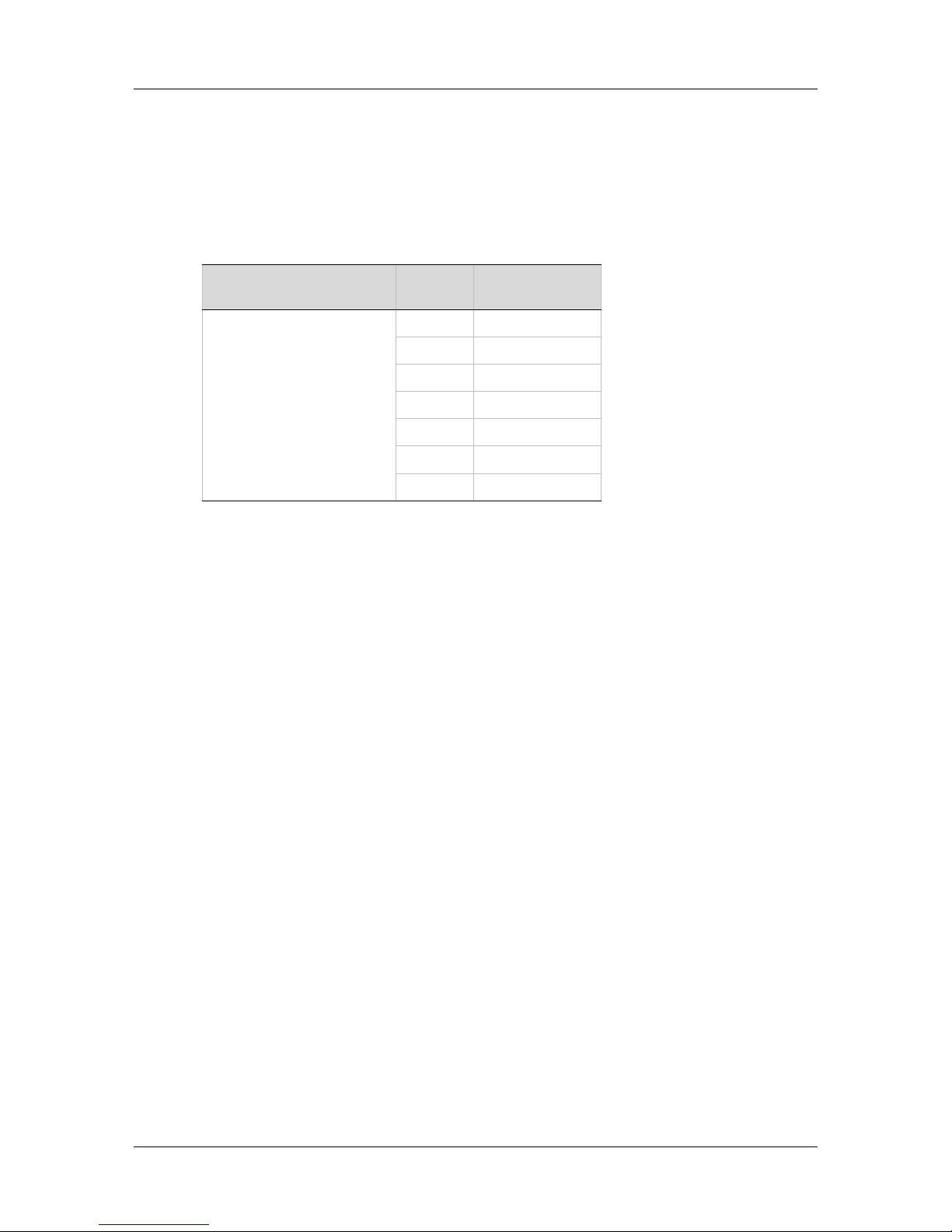
Host Computer
The FLEXI PRO can be connected to the host computer through either one of two
serial interfaces:
USB Interface (C1). Use a USB 2.0 A to Mini-B cable.
RS232 Interface (C7). Use a 4p4c plug.
RS232 Interface (C7)
All FLEXI PRO
120/240 VAC Models
Pin
Pin
Label
Function
C7
1 RX Receive
2 GND ISO Ground
3 TX Transmit
4 Unused
Page 39
FLEXI PRO
Quick Start Guide 39
Daisy Chain
The FLEXI PRO can be addressed and controlled on a daisy-chained RS232 line.
In a daisy-chain RS232 configuration, all drives must be daisy-chained through the
C8 connector. Each drive must have a unique address to enable its identification
on the network.
Daisy Chain Interface (C8)
All FLEXI PRO
120/240 VAC Models
Pin Function
C8
1 DC Shield
2 Unused
3 RXD
4 GND
5 TXD
6 GND
7-10 Unused
Drive Address Switches
Two rotary switches are used to set the drive address for both CAN and serial
communication.
Each switch has 10 positions:
The upper switch positions are set as tens: 10, 20, 30 … 90
The lower switch positions are set as ones: 0, 1, 2 … 9
Each drive on the network must have a unique address.
If two or more drives are connected to the network, address 0 cannot be used.
A single drive may have the address 0
Page 40
FLEXI PRO
40 Quick Start Guide
4 Power Board 120/240 VAC
Make sure the main voltage rating matches the drive specification.
Applying incorrect voltage may cause drive failure.
Do not apply power until all hardware connections are complete.
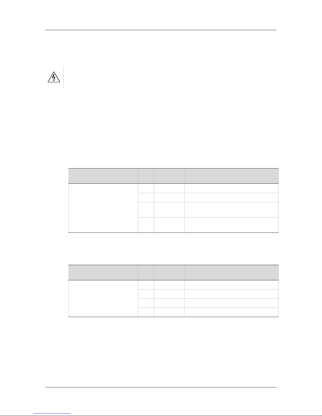
Safe Torque Off (STO)
Safe torque off (STO) is a safety function that prevents the drive from delivering
power to the motor, which can generate torque.
STO Enable and STO Return must be connected to enable FLEXI PRO operation.
The STO Enable signal voltage must be 24 VDC.
If the application does not require STO control, jumper pin 4 to pin 1, and pin 3 to
pin 2, to bypass the STO.
STO Interface (P1)
All FLEXI PRO
120/240 VAC Models Pin Pin Label Function
P1
1 24V STO Enable
2 GND STO Return
3 24V Return, provided by the drive
for use with emergency stop circuit
4 24V Supply, provided by the drive
for use with emergency stop circuit
Motor
Motor Interface (P2) (P4*)
All FLEXI PRO
120/240 VAC Models Pin Pin Label Function
P2
P4*
1 PE Functional ground (motor housing)
2 U Motor Phase U
3 V Motor Phase V
4 W Motor Phase W
* Exception: P4 on FLEXI PRO-020/024, 120/240 VAC
Page 41
FLEXI PRO
Quick Start Guide 41
Regeneration Resistor
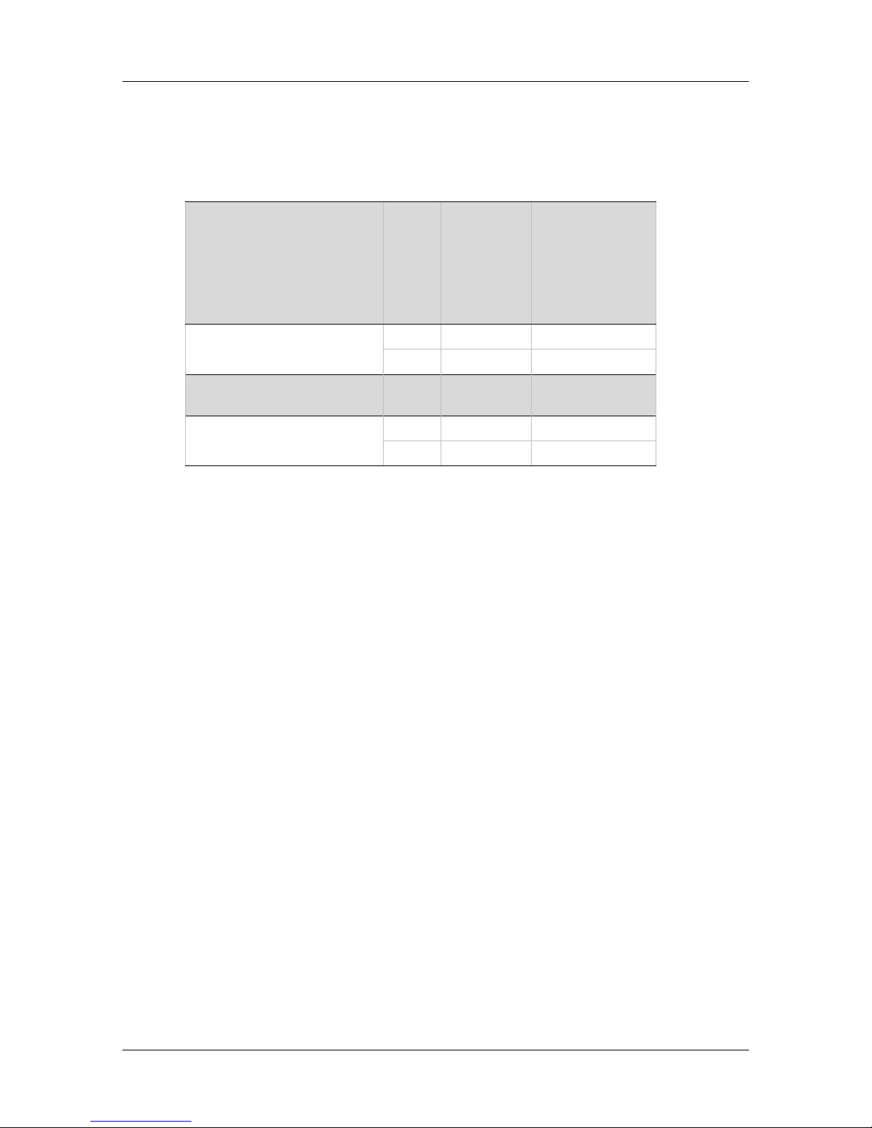
If the application requires a regeneration (regen) resistor, connect the regen
resistor between terminals B1+ and B2.
Regen Interface (P3) (P5)
FLEXI PRO-1D5, FLEXI
PRO -003
FLEXI PRO -4D5, FLEXI
PRO -006
FLEXI PRO -008, FLEXI
PRO -010
FLEXI PRO -013 Pin Pin Label Function
P3
1 B1+ DC bus +
2 B2 Regen bus -
FLEXI PRO -020, FLEXI
PRO -024
Pin Pin Label Function
P5
1 B2 Regen bus -
2 B1+ DC bus +
Regen and AC Input Voltage are combined on one interface on
FLEXI PRO-1D5 and FLEXI PRO-003, 120/240 VAC.
AC Input
The AC Input interfaces vary among FLEXI PRO 120/240 VAC models.
FLEXI PRO-1D5 and FLEXI PRO-003: One interface (P3) for bus power and
logic power.
FLEXI PRO-4D5 and FLEXI PRO-006: One interface (P4) for bus power and
logic power.
FLEXI PRO-008, FLEXI PRO-010 and FLEXI PRO-013: One interface (P4) for
bus power; one interface (P5) for logic power.
FLEXI PRO-020/024: One interface (P3) for bus power; one interface (P2) for
logic power.
Make the following connections:
1. Connect the AC input voltage ground wire to the PE terminal, located on the
FLEXI PRO front panel. Use an M4 ring or spade terminal.
2. Connect L1, L2 and L3 (for bus power):
If the main voltage is from a single-phase source, connect line and neutral
to L1 and L2.
If the main voltage is from a three-phase source, connect the phases to
L1, L2 and L3.
3. Connect L1C and L2C (for logic power):
If the main voltage is from a single-phase source, connect line and neutral
to L1C and L2C.
Page 42
FLEXI PRO
42 Quick Start Guide
If the main voltage is from a three-phase source, connect any two phases
to L1C and L2C.
Prevent inrush surge:
Bus Power (L1-L2-L3): After switching on bus power, wait 1 minute before
switching on again, regardless of time in Off state.
Logic Power (L1C-L2C): After switching off logic power, wait 1 minute before
switching on again.
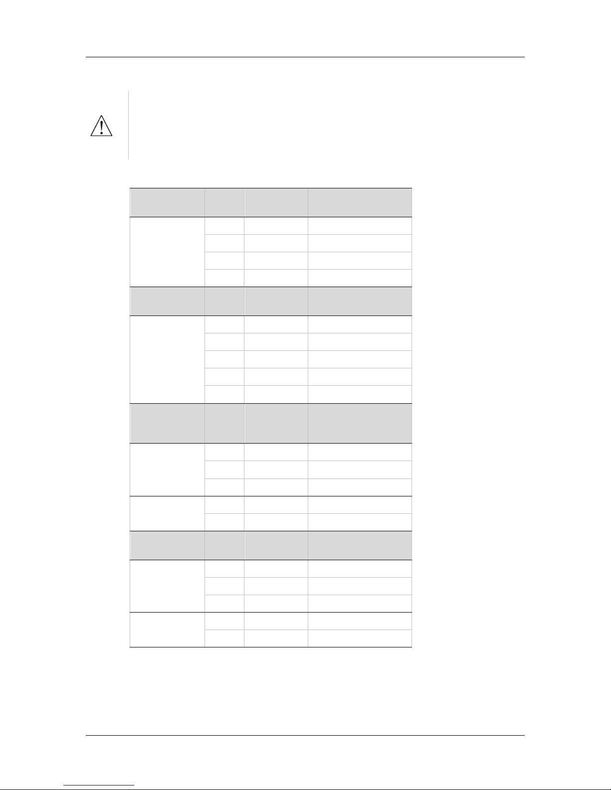
AC Input Interface (P3, P4, P5)
FLEXI PRO-1D5
FLEXI PRO-003 Pin Pin Label Function
P3
3 L1 AC Phase 1
4 L2 AC Phase 2
5 L1C Logic AC Phase 1
6 LC2 Logic AC Neutral
FLEXI PRO -4D5
FLEXI PRO -006 Pin Pin Label Function
P4
1 L1 AC Phase 1
2 L2 AC Phase 2
3 L3 AC Phase 3
4 L1C Logic AC Phase 1
5 LC2 Logic AC Neutral
FLEXI PRO -008
FLEXI PRO -010
FLEXI PRO -013 Pin Pin Label Function
P4
1 L1 AC Phase 1
2 L2 AC Phase 2
3 L3 AC Phase 3
P5
1 L1C Logic AC Phase 1
2 LC2 Logic AC Neutral
FLEXI PRO -020
FLEXI PRO -024
Pin Pin Label Function
P3
1 L1 AC Phase 1
2 L2 AC Phase 2
3 L3 AC Phase 3
P2
1 L1C Logic AC Phase 1
2 LC2 Logic AC Neutral
AC Input Voltage and Regen are combined on one interface on
FLEXI PRO-1D5 and FLEXI PRO-003, 120/240 VAC.
Page 43
FLEXI PRO
Quick Start Guide 43
5 Power Board 400/480 VAC
Make sure the main voltage rating matches the drive specification.
Applying incorrect voltage may cause drive failure.
Do not apply power until all hardware connections are complete.
Safe Torque Off (STO)
Safe torque off (STO) is a safety function that prevents the drive from delivering
power to the motor, which can generate torque.
STO Enable and STO Return must be connected to enable FLEXI PRO operation.
The STO Enable signal voltage must be 24 VDC.
If the application does not require STO control, jumper pin 4 to pin 1, and pin 3 to
pin 2, to bypass the STO.
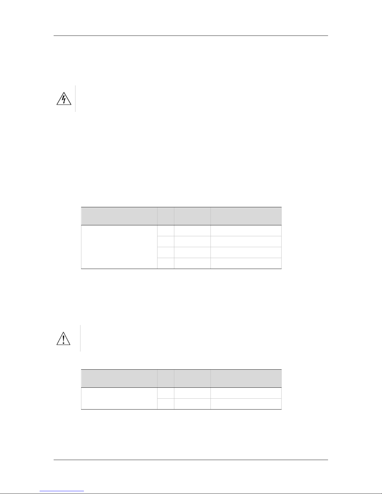
STO Interface (P1) (P3*)
All FLEXI PRO
400/480 VAC Models Pin Pin Label Function
P1
P3*
1 24V STO Enable
2 GND 24 VDC Return
3
4
* Two STO interfaces on FLEXI PRO-24 and FLEXI PRO-30, 400/480 VAC.
Logic Power 24V Input
This interface is used to connect an external power supply (24V 3.15A max.) that
provides the logic voltage to the control board and to the motor brake circuit.
Prevent inrush surge:
Logic Power (L1C-L2C): After switching Logic Power Off, wait 1 minute before
switching On again.
Logic Power 24V Interface (P2)
All FLEXI PRO
400/480 VAC Models Pin Pin Label Function
P2
1 24V Logic In
2 GND 24 VDC Return
Page 44
FLEXI PRO
44 Quick Start Guide
AC Input and Regeneration Resistor
AC Input and Regen Resistor are combined on one connector on the FLEXI
PRO 400/480 VAC models.
1. Connect the AC input voltage ground wire to the PE terminal, located on the
FLEXI PRO front panel. Use an M4 ring or spade terminal.
2. Connect L1, L2 and L3 (for bus power)
3. If the application requires a regeneration (regen) resistor, connect the regen
resistor between terminals B1+ and B2.
Prevent inrush surge:
Bus Power (L1-L2-L3): After switching Bus Power On, wait 1 minute before
switching On again, regardless of time in Off state.
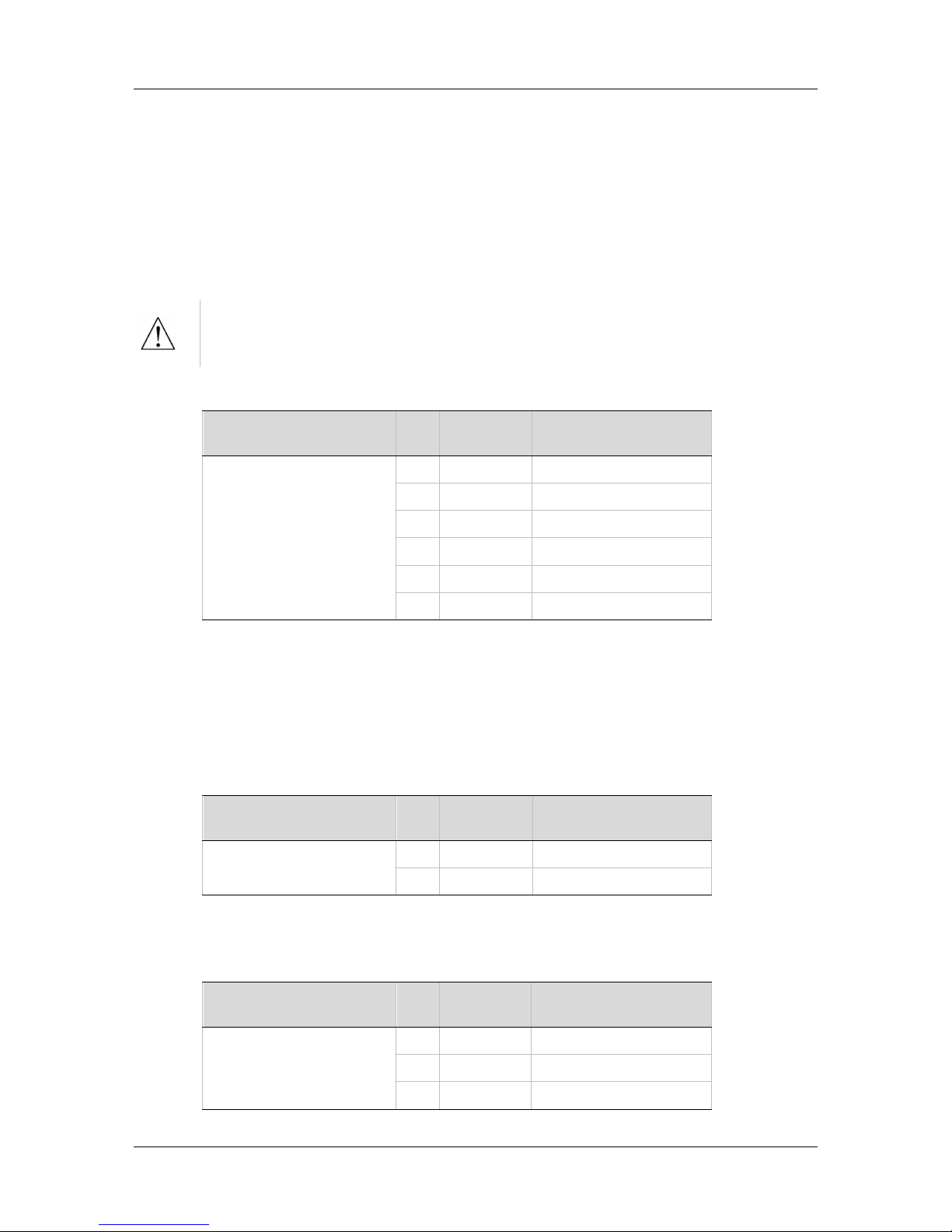
AC Input and Regeneration Resistor Interface (P3) (P5)
All FLEXI PRO
400/480 VAC Models Pin Pin Label Function
P3
P5
1 L1 AC Phase 1
2 L2 AC Phase 2
3 L3 AC Phase 3
4 B1+ DC Bus +
5 B2 Regen Bus
6 B3- DC Bus -
P3 on FLEXI PRO-003/FLEXI PRO-006/FLEXI PRO-012, 400/480 VAC.
P5 on FLEXI PRO-024/FLEXI PRO-030, 400/480 VAC.
Brake
This interface is the power output for the electric motor brake system.
Brake Interface (P4)
All FLEXI PRO
400/480 VAC Models Pin Pin Label Function
P4
1 BR+ Motor Brake +
2 BR- Motor Brake -
Motor
Motor Interface (P5)
All FLEXI PRO
400/480 VAC Models Pin Pin Label Function
P5
1 U Motor Phase U
2 V Motor Phase V
3 W Motor Phase W
Page 45

FLEXI PRO
Quick Start Guide 45
6 Software
Flexi SUITE Installation
Use Flexi SUITE software to configure the drive for your application.
1. Install Flexi SUITE on the host computer.
2. When installation is complete, start Flexi SUITE.
Power Up
1. After completing the hardware connections, turn on power to the drive.
2. The first time the drive is connected to the host computer on the USB port,
Windows detects the device and displays a Found New Hardware wizard.
Browse to and select the \Motor Power Company\FlexiSUITE\Drivers folder.
The wizard will automatically select and install the driver file.
3. Look at the 7-segment display on the FLEXI PRO front panel.
Upon initial power up, the status display shows a flashing e, indicating that
drive parameters are not yet configured. This fault will be cleared once the
drive is configured.
Drive Configuration
1. In Flexi SUITE, select the Motor Setup wizard from the navigation menu.
Follow the prompts to configure the FLEXI PRO for your particular motor.
2. When Motor Setup is complete, use the Flexi SUITE Autotuning wizard to
optimize drive parameters for your particular application.
Page 46
FLEXI PRO
46 Quick Start Guide
7 Drive Status (7-Segment Display)
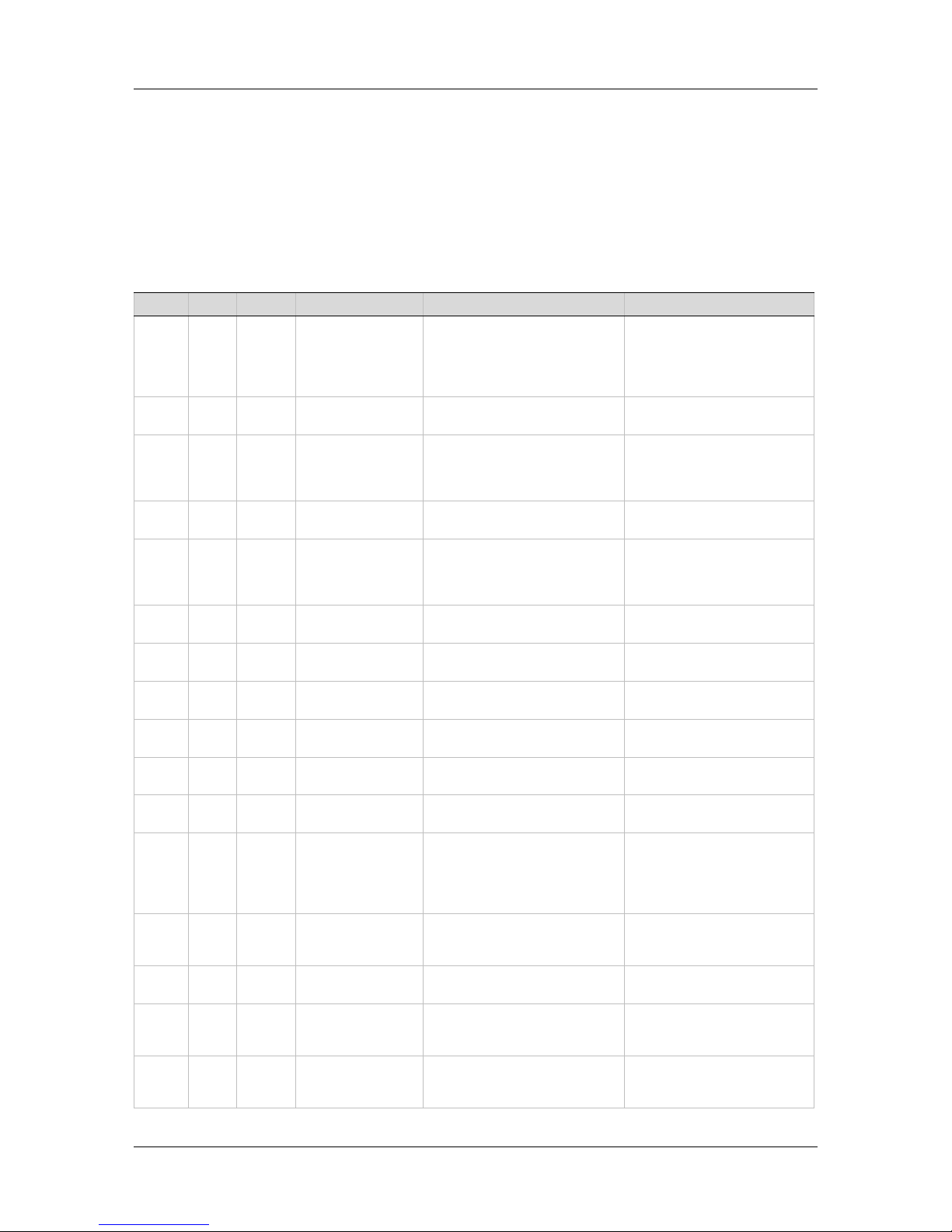
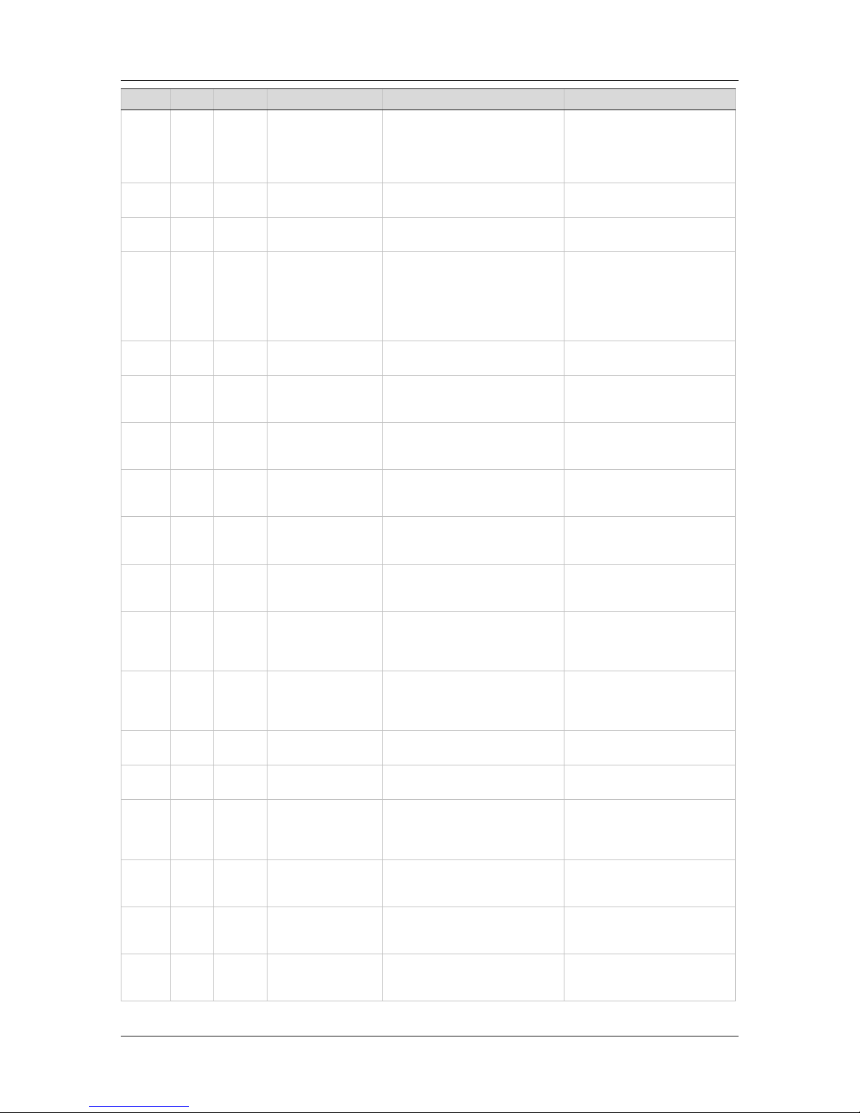
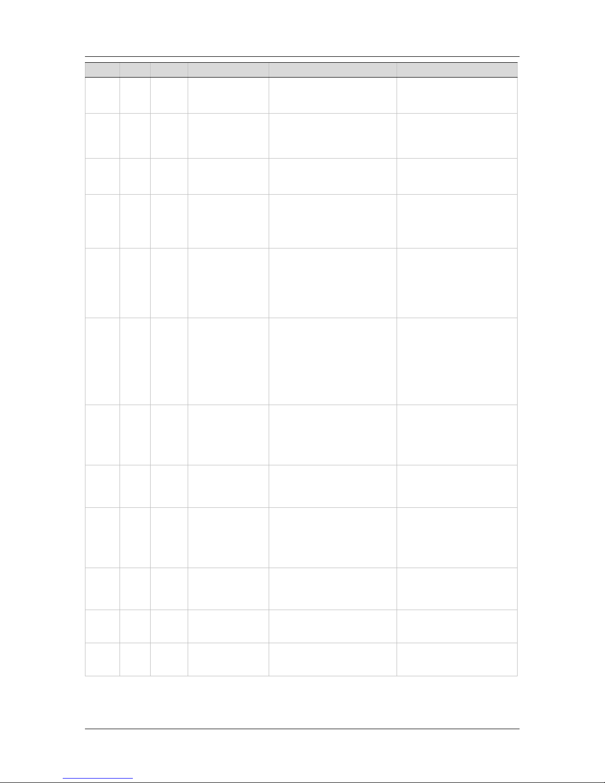
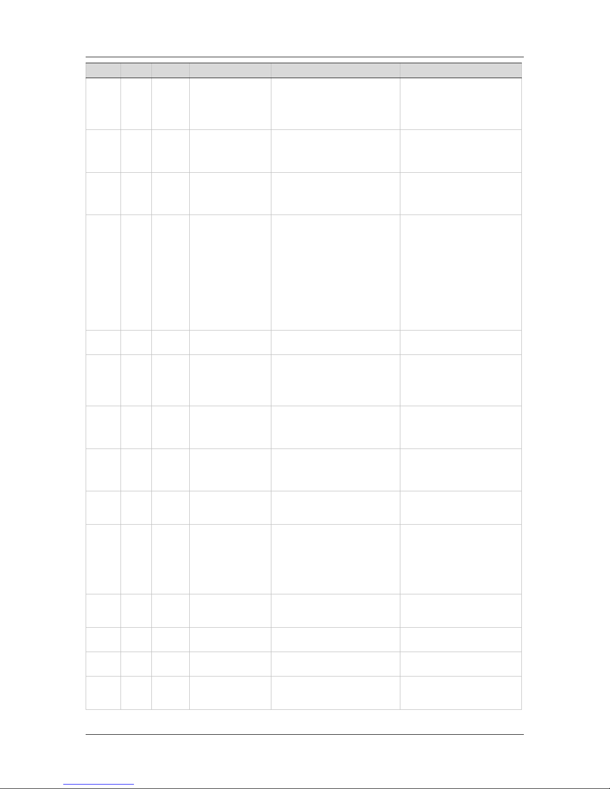
The 7-segment display provides indications of drive status, such as operation
modes, drive enable status, and fault conditions.
7-Segment Display Codes
Code Light Type Name Description Action Required
-5 Fault Motor Setup Failed Motor Setup procedure failed
(MOTORSETUPST will show the
reason)
Check phase and motor wiring.
Make sure to choose the
correct feedback type, and
follow the hints in
MOTORSETUPST.
-1 Fault Not Configured Drive configuration required. Set drive parameters and
execute CONFIG.
_ Flash Fault Realtime Overload
Fault
CPU has exceeded its
computational limit. Realtime
execution takes longer than
31.25 µs.
Contact technical support.
_ Steady Warning Realtime Overload
Warning
Drive has detected that CPU is
close to its computational limit.
≡
Flash Fault Watchdog Fault Generally occurs due to an
unforeseen circumstance. The
drive is inoperable until power is
cycled.
Contact technical support.
0 | 0. Mode Operation Mode 0 Serial Velocity.
Drive disabled | enabled.
1 | 1. Mode Operation Mode 1 Analog Velocity.
Drive disabled | enabled.
2 | 2. Mode Operation Mode 2 Serial Current
Drive disabled | enabled.
3 | 3. Mode Operation Mode 3 Analog Current.
Drive disabled | enabled.
4 | 4. Mode Operation Mode 4 Gearing.
Drive disabled | enabled.
8 | 8. Mode Operation Mode 8 Profile Position
Drive disabled | enabled.
8. Mode Hardware Ember
Switch Activated
All segments light up when the
Hardware Ember switch is
pressed, which sets the drive to
serial communication Boot-Up
Mode.
A4 Fault CAN Supply Fault A problem with the internal
voltage supply for the CAN bus.
The drive probably needs
repair. Contact technical
support.
At1 Mode Motor Setup in
Progress
Motor initialization routine is
being executed.
b Flash Fault Drive Locked Security code and key do not
match. Fatal fault; drive cannot
be operated.
Contact technical support.
b Steady Warning Tamagawa Battery
Low-Voltage
Battery voltage is nearing fault
level. Relevant only for
Tamagawa encoder.
Prepare to replace battery
soon.
Page 47
FLEXI PRO
Quick Start Guide 47
Code Light Type Name Description Action Required
b1
Fault PLL (phase-locked
loop)
Synchronization
Failed
Controller synchronization signal
is missing or not stable.
The fault
is detected only when
synchronization is enabled by
SYNCSOURCE command.
Check if controller provide
synchronization signal. Check
the cable connection and
wiring.
c Steady Warning Regen Resistor
Overload
Regeneration resistor is
overloaded.
C1 Fault CAN Heartbeat Lost Drive detected disconnection
between CAN master and drive.
Reconnect master and slave,
and power cycle the drive.
e Flash Fault Parameter Memory
Checksum Failure
The non-
volatile memory used to
store drive parameters is empty
or the data is corrupted.
May occur during power off if
SAVE operation has not
completed.
Reconfigure the drive, or
download the parameter set,
and save the parameters.
If problem persists, contact
technical support.
E Steady Mode Ember Mode Firmware is being updated in the
drive.
E Flash Fault Failure Writing to
Flash Memory
An internal problem accessing
the flash memory. Fatal fault;
drive cannot be operated.
Contact technical support.
e101 Fault FPGA Config Fail The code for the FPGA did not
load. Fatal fault; drive cannot be
operated.
Contact technical support.
e105 Fault Self Test Fail The power-up self test failed.
Fatal fault; drive cannot be
operated.
Contact technical support.
e106 Fault Control EEPROM
Fault
A problem accessing the EEPROM
on the control board. Fatal fault;
drive cannot be operated.
Contact technical support.
e107 Fault Power EEPROM Fault
A problem accessing the EEPROM
on the power board. Fatal fault;
drive cannot be operated.
Contact technical support.
e108 Fault Vbus Measure
Circuit Fail
A failure occurred in the circuit
that measures bus voltage.
Reset faults. If the fault
persists, the drive probably
needs repair. Contact technical
support.
e109 Fault Current-Sensors
Offset Out-of-Range
The calculated offsets for the
current sensors are out of range.
Reset faults. If the fault
persists, the drive probably
needs repair. Contact technical
support.
e120 Fault FPGA Version
Mismatch
FPGA version does not match the
firmware version
Update either the FPGA version
or drive version
e121 Fault Internal Error Internal error due to an endless
while loop or a numerical issue
Contact technical support.
e123 Fault Motor Plate Read
Failed
Motor type nameplate data
cannot be read.
Reconnect the feedback
device. Make sure the motor
type nameplate data is
present.
e124 Fault SAVE and Power
Cycle Required
Parameter was changed, and
requires SAVE and power cycle
to take effect.
SAVE and then cycle power to
the drive.
e125 Fault Fieldbus Version
Mismatch
EtherCAT - the MicroBlaze
version does not match the
version specified by drive.
Make sure the correct version
has been downloaded to the
drive.
e126 Fault ESI Version
Mismatch
EtherCAT - the ESI version does
not match the version specified
by drive.
Make sure the correct version
has been downloaded to the
drive.
Page 48
FLEXI PRO
48 Quick Start Guide
Code Light Type Name Description Action Required
e127 Fault Output Over-
Current
Detected
Over-current detected on one of
the digital outputs.
This fault disables the drive.
Verify correct wiring of the
digital outputs. Make sure the
output circuit is not shorted.
e129 Fault Feedback Type
Auto-Detection
Failed
Feedback type auto-detection
failed to identify the type of
feedback device.
This fault disables the drive.
Verify the connection.
Manually configure the actual
type of feedback.
e130 Fault EnDat Excessive
Resolution
EnDat high resolution feedback
cannot be handled by the drive.
This fault disables the drive.
e131 Fault MOTORNAME/MTP
Data Mismatch
Drive may have been configured
previously for another, different
motor.
This fault disables the drive.
Clear MOTORNAME and clear
faults.
Perform tuning with
parameters for the connected
motor.
F Steady Warning Foldback Drive fold current dropped below
the drive fold current warning
threshold (MIFOLDWTHRESH).
Or, motor fold current dropped
below the motor fold current
warning threshold
(IFOLDWTHRESH).
Check the drive-motor sizing.
This warning can occur if the
drive or the motor is undersized (under-powered) for the
application.
F1 Fault Drive Foldback Drive fold current dropped below
the drive fold current fault
threshold (MIFOLDFTHRESH).
Check motor-drive sizing. This
fault can occur if the drive is
under-sized (under-powered)
for the application.
Check that the commutation
angle is correct (i.e.,
commutation is balanced).
Check MIFOLDFTHRESH and
MIFOLDWTHRESH values
F2 Fault Motor Foldback
Motor fold current dropped below
the motor fold current fault
threshold. (IFOLDFTHRESH).
Check the drive-motor sizing.
This fault can occur if the
motor is under-sized (underpowered) for the application.
Check IFOLDFTHRESH and
IFOLDWTHRESH values.
F2H Fault Pulse Train
Frequency Too High
The external pulse train
frequency has exceeded the
maximum specified input
frequency.
Reduce the frequency of the
gearing pulses commanded
from the controller.
F3 Fault Stall Fault
A stall fault occurred because the
motor was in a stalled state for
too long; that is, [I > MICONT]
and [I > 0.9 ILIM] and [V <
STALLVEL] for [time >
STALLTIME].
Remove the stall condition,
and take care to prevent stall
conditions.
Fb1 Fault Fieldbus – Target
position exceeds
velocity limit
A target position command from
controller was rejected because
it would cause the motor to
exceed the velocity limit.
Enable the drive and send
valid position commands.
Fb3 Fault EtherCAT – Cable
disconnected
The connection between
controller and drive was
removed.
Reestablish the connection
between controller and drive.
Fb4 Fault Fieldbus Target
Command Lost
The fieldbus controller has not
sent a target command in 3
consecutive instances.
Clear the fault and allow the
controller to send new
commands.
Page 49
FLEXI PRO
Quick Start Guide 49
Code Light Type Name Description Action Required
Fb7 Fault CAN is in Bus-Off
State
The drive has disconnected from
the CAN bus due to
communication errors, and is no
longer sending/receiving
communication packets.
Check CAN cabling, and verify
the CAN network is functioning
properly.
Fb8 Fault EtherCAT Packet
Loss
EtherCAT packets have been
lost.
Make sure the EtherCAT
master (controller) sends the
packets within the time
defined (by the master).
Fb9 Fault Fieldbus - Drive
Active but not in
Operational State
Drive was enabled and in an
operational state upon receiving
a command to move to a lower
state of communication.
Make sure the controller does
not switch to a lower state of
communication while the drive
is enabled.
H Flash Fault Motor Over-
Temperature
Either the motor has overheated,
or the drive is not set up
correctly for the motor
temperature sensor.
Check that the drive is
configured properly (using
THERMODE, THERMTYPE,
THERMTHRESH and
THERMTIME), and that the
motor temperature sensor is
properly connected to the
drive if needed.
If the drive is configured and
wired properly, check whether
the motor is under-sized for
the application.
H Steady Warning Motor Over-
Temperature
Motor is overheated.
J Flash Fault Velocity Over-Speed
Exceeded
Actual velocity exceeded 1.2
times the velocity limit. The
velocity limit is set using VLIM.
Check that VLIM is set to
match the application
requirements. Using velocity
loop tuning, check for
excessive overshoot.
J1 Fault Exceeded Maximum
Position Error
The position error (PE) has
exceeded the position error limit
(PEMAX)
Change drive tuning to
improve position tracking, or
increase PEMAX to allow a
greater position error.
J2 Fault Exceeded Maximum
Velocity Error
The velocity error (VE) has
exceeded the velocity error limit
(VEMAX)
Change drive tuning to
improve velocity tracking, or
increase VEMAX to allow a
greater velocity error.
J3 Fault Excessive PE Value The position error (PE) has
reached the software numerical
limit.
Check tuning.
J4 Fault Motor Runaway
Condition Detected
The motor moves in negative
direction although the
commanded current is positive.
Commutation is incorrect.
(Algebraic signs of actual
current, acceleration and velocity
do not match.)
Correct MPHASE setting.
Activate and improve the
phase find process.
J5 Fault
Secondary Feedback
Position Mismatch
Position deviation between motor
and load is too great.
Increase SFBPETHRESH,
SFBPETIME, SFBPEMAX, or
improve position tuning.
L1 Warning Hardware positive
limit switch is open
Positive hardware limit switch is
activated.
L2 Warning Hardware negative
limit switch is open
Negative hardware limit switch is
activated.
L3 Warning Hardware positive
and negative limit
switches are open
Positive and negative hardware
limit switches are both activated.
Page 50
FLEXI PRO
50 Quick Start Guide
Code Light Type Name Description Action Required
L4 Warning Software positive
limit switch is
tripped
Positive software limit switch is
activated.
PFB > POSLIMPOS and
POSLIMMODE = 1
L5 Warning Software negative
limit switch is
tripped
Negative software limit switch is
activated.
PFB < POSLIMNEG and
POSLIMMODE = 1
L6 Warning Software limit
switches are tripped
Positive and negative software
limit switches are activated.
PFB > POSLIMPOS and
PFB < POSLIMNEG and
POSLIMMODE = 1
n Flash Fault STO Fault The STO signal is not connected
when drive enabled.
Check that the STO connector
(P1) is wired correctly.
n Steady Warning STO The STO signal is not connected
when drive disabled.
Check that the STO connector
(P1) is wired correctly.
n1 Fault Regen Over- Current
The preset current limit for regen
current has been exceeded.
Increase the value of the
regen resistor.
n3 Fault Emergency Stop
Issued
The input defined as emergency
stop has been activated.
Turn off the specific input.
n43 Fault Invalid Gain Table
Data
The condition LMJRGT1 <
LMJRGT2 <LMJRGT3 has not
been met.
Modify and correct the gain
tables.
n45 Fault Power Brake Fault A fault occurred on the power
brake.
Replace the motor brake.
o Flash Fault Over-Voltage The bus voltage exceeded the
maximum value.
Check whether a regen resistor
is required for the application.
o Steady Warning Bus AC Supply Line
Disconnected
At least one phase of the main
power for the bus supply is not
connected.
o15 Fault Plus 15V Out of
Range
The internal +15 V supply is out
of range.
The drive probably needs
repair. Contact technical
support.
o-15 Fault Minus 15V Out of
Range
The internal -15 V supply is out
of range.
The drive probably needs
repair. Contact technical
support.
o5 Fault 5V Out of Range 5V is low or powering off. May occur during power off.
If occurs otherwise, contact
technical support.
o6 Fault Logic AC Power
Failure
The main power for the logic
supply is off.
No action required. This is a
normal response when logic
power is turned off.
o7 Fault Bus AC Supply Line
Disconnect
At least one phase of the main
power for the bus supply is not
connected.
Check the connection of the
bus AC supply. Make sure the
supply is on.
o8 Fault Regen Resistor
Overload
The regen resistor load exceeds
its allowed power.
Check whether the regen
resistor properties are suited
to the application.
o9 Fault Digital Output Over-
Current
Over-
current at the digital output
has been detected.
This fault disables the drive.
Check the digital output
connections.
Page 51
FLEXI PRO
Quick Start Guide 51
Code Light Type Name Description Action Required
P Fault Over-Current Over-current at the drive output
has been detected.
The drive allows this fault to
occur up to 3 times in
succession. After 3 faults, the
drive forces a delay of 1 minute
before it can be reenabled.
Check for a short circuit on the
motor connection.
Check for excessive overshoot
in the current loop.
P2 Fault Unstable Current
Loop
An unexpected high current
overshoot has been detected
Check and modify current
controller settings.
P3 Fault High IQ Current
Detected
The detected IQ current is
greater than 120% of ILIM.
This fault disables the drive.
Check and modify current
controller settings.
r Steady Warning Offset and/or Gain
Adjustment Values
Detected After
SININIT
Significant offset and/or gain
adjustment values were detected
after SININIT.
The values that trigger this
warning are half the value of
those used to declare a fault.
Although the system may
continue to function, these
values indicate the existence of a
problem, which may worsen over
time.
Check the encoder and
associated hardware.
These values suggest some
degradation in either
electronics (e.g., encoder,
drive) or wiring (e.g.,
increased wire resistance,
increased leakage between
wires). The problem must be
analyzed and repaired.
r10 Fault Sine Feedback
Communication Fail
Communication problem between
the drive and EnDat/HIPERFACE
encoder.
Check that the data and clock
signals to the EnDat or
HIPERFACE encoder are
connected properly. The cable
must be shielded.
r14 Fault Sine Encoder
Quadrature Fault
Mismatch between calculated
and actual encoder quadrature
information.
Check the feedback device
wiring.
Check that the correct encoder
type (MENCTYPE) is selected.
r15 Fault Sin/Cos Calibration
Invalid
The sine/cosine calibration
parameters are out of range.
This fault is related to resolver
and sine encoder feedback.
Re-execute the sine/cosine
calibration process.
r16 Fault Feedback 5V Over-
Current
The current supplied by the drive
on the 5V primary encoder
supply has exceeded the preset
current limit.
The drive allows this fault to
occur up to 3 times in
succession. After 3 faults, the
drive forces a delay of 1 minute
before it can be reenabled.
The FLEXI PRO can source a
maximum current of 250 mA
to the primary encoder.
Check for a short-circuit on
the
encoder.
Check if the encoder is
drawing more than the current
limit.
r17 Fault
Secondary Feedback
Index Break
Secondary encoder index line not
connected.
Check whether the drive is
configured for working with the
index signal on the secondary
encoder, and check if the
index signal is connected.
r18 Fault
Secondary Feedback
A/B Line Break
One of the secondary feedback
signals is not connected.
Check that all signals from the
secondary encoder are
properly connected to the
drive.
r19 Fault
Secondary Feedback
5V Over-Current
The preset current limit for
current supplied by the drive on
the 5 V secondary encoder
supply has been exceeded.
The FLEXI PRO can source a
maximum current of 250 mA
to the secondary encoder.
Check for a short-circuit at the
encoder.
Check if the encoder is
drawing more than the current
limit.
Page 52
FLEXI PRO
52 Quick Start Guide
Code Light Type Name Description Action Required
r20 Fault Feedback
Communication
Error
Communication with the
feedback device did not initialize
correctly.
Check that the feedback device
is wired correctly.
Check that the correct encoder
type (MENCTYPE) is selected.
r21 Fault Nikon Encoder
Operational Fault
Communication with the Nikon
MAR-A40A feedback device did
not initialize correctly.
Check that the feedback device
is wired correctly. Check that
the correct encoder type
(MENCTYPE) is selected.
r23 Fault Phase Find Failed Commutation initialization has
failed. This fault occurs in
systems that do not have
commutation information (e.g.,
Hall signals) in the motor
feedback device.
Check whether the motor
feedback type and the phasefinding parameters are set
correctly for the application.
r24 Fault Tamagawa Init
Failed
The initialization process with the
Tamagawa feedback device has
failed.
Check that the wiring to the
encoder is correct.
r25 Fault Pulse & Direction
Input Line Break
One of the Pulse & Direction
signals is not connected.
Check that all signals to the
P&D inputs are properly
connected to the drive.
r26 Fault Tamagawa Abs
Operational Fault
Several faults are indicated by
the feedback device and include
one or more of the following:
battery low/error, over-speed,
counting error, multi-turn error
Check the battery voltage and
feedback wiring. Make sure the
motor did not move at a high
velocity during encoder
initialization.
r27 Fault Motor Phases
Disconnected
One of the motor phases is
disconnected. The current of one
of the motor phases is effectively
zero for more than 160 electrical
degrees while the current
command is greater than 100.
Check the wiring of the motor
phases.
r28 Fault Resolver
Initialization Failed
The drive could not detect the
proper gain setting or sampling
point for the sine/cosine signals.
Check resolver wiring and gain
value.
r29 Fault Absolute Encoder
Battery Low-Voltage
An error bit indicating a battery
problem was detected in data
from the drive.
Replace battery, then reset
drive. If battery is replaced
while drive is on, position
information is retained.
r32 Fault Endat2X Feedback
Fault
CRC error occurred while drive
was communicating with EnDat
encoder. Also caused by EnDat
encoder setting Alarm bit/s to
indicate an encoder problem.
This fault disables the drive.
Reset the encoder including
encoder power off.
r33 Fault Custom Absolute
Encoder Internal
Faults
Several possible issues are
indicated by this feedback device
fault: battery low or error; overspeed; counting error; multiturn
error.
Check the battery voltage and
feedback wiring. Make sure the
motor did not move at a high
velocity during encoder
initialization.
r34 Fault PFB Off Checksum
Invalid
The calculated checksum of the
PFB backup data does not match
the expected checksum.
If required by the application,
home the machine.
r35 Fault PFB Off Data
Mismatch
Multi-
turn data of the PFB cannot
be restored due to axis
movement.
If required by the application,
home the machine.
r36 Fault No PFB Off Data PFB backup memory is empty. If required by the application,
home the machine.
Page 53
FLEXI PRO
Quick Start Guide 53
Code Light Type Name Description Action Required
r37 Fault Encoder Phase Error In normal incremental encoder
operation, quadrature inputs A
and B are 90 degrees out of
phase. The phase error occurs
when edge transition is detected
simultaneously on the A and B
signals.
Set MENCAQBFILT to 0 to
remove the filter on A and B
signals. If problem persists, it
may be due to a faulty
encoder.
r38 Fault Differential Halls
Line Break
Line break in differential Hall
sensors.
Make sure HALLSTYPE matches
the Hall sensors in use (singleended or differential).
Check whether all signals from
the differential Hall sensors are
properly connected to the
drive.
r39 Fault AqB Commutation
Fault
Loss of commutation/encoder
counts for AqB encoder.
The index signal serves as a
reference position for detecting
loss of commutation/pulses. The
AqB encoder counter is
compared at different index
positions. Between index position
captures the count must be
exactly MENCRESx4 (or 0 counts
if moved back to same index
location).
If a fault occurs shortly after
motion begins, check
MENCRES settings.
If a fault occurs after some
time it is likely due to EMI
noise. Improve the installation.
Make sure ground is
connected. Make sure shield is
connected on feedback and
motor cables.
r4 Fault A/B Line Break One of the primary feedback
signals is not connected. This
fault occurs in incremental
encoder, resolver and sine
encoder feedback types.
Check whether all signals from
the primary feedback device
are properly connected to the
drive.
r40 Fault ServoSense Encoder
Fault
The drive has detected an
internal fault on the ServoSense
encoder through communication.
Use command SRVSNSINFO to
identify the fault.
r41 Fault Sankyo Absolute
Encoder Fault
One or more faults are indicated
by the feedback device,
including: battery low or error,
over-speed, counting error,
multi-turn error.
Check the battery voltage and
feedback wiring. Make sure the
motor did not move at a high
velocity during encoder
initialization.
r42 Fault BiSS-C Encoder
Indicates Internal
Fault
This fault disables the drive. Refer to the BiSS-C encoder
manufacturer specific
documentation.
r43 Fault HIPERFACE Data
Error
This fault disables the drive. Enter the command HSAVE 1.
r5 Fault Index Line Break Encoder index line is not
connected.
Check that the drive is
configured
for working with the
index signal (using
MENCTYPE), and check if the
index signal is connected.
r6 Fault Invalid Halls The drive has detected either
000 or 111 state on the Hall
feedback signals.
Check that the Hall signals are
all properly connected. While
turning the motor, read the
Halls state (using HALLS) to
see which signal is not
connected.
If the feedback type is
Tamagawa, check that the
feedback wiring is correct
Page 54
FLEXI PRO
54 Quick Start Guide
Code Light Type Name Description Action Required
r8 Fault A/B Out of Range Feedback analog signal is out of
range. This fault is related to
resolver and sine encoder
feedback. The drive checks that
the amplitudes of the sine and
cosine signals are correct, based
on the calculation sin2 + cos2 =
1
Check the amplitudes of the
sine and cosine signals.
r9 Fault Encoder Simul
Frequency Too High
The computed equivalent
encoder output frequency
exceeds the upper limit for this
signal, which is 4 MHz.
Check the parameters used for
setting up the equivalent
encoder output.
If using a sine encoder, check
the ENCOUTRES parameter
settings.
S1 Warning
Cannot Use SFBTYPE
1 with Analog
OPMODE
Cannot use the specified type of
secondary feedback with analog
operation modes (i.e., OPMODE
1, OPMODE 3)
t Steady Warning Over-Temperature The temperature on the power
board and/or on the control
board and/or the power module
(IPM) has exceeded the preset
limit.
Check if the ambient
temperature exceeds the drive
specification. Otherwise
contact technical support.
t1 Fault Power Stage Over-
Temperature
The temperature on the power
board has exceeded the preset
limit.
Check if the ambient
temperature exceeds the drive
specification. Otherwise
contact technical support.
t2 Fault Power Module Over-
Temperature
The temperature inside the
integrated power module has
exceeded the preset limit.
Check if the ambient
temperature exceeds the drive
specification. Otherwise
contact technical support.
t3 Fault Control Board Over-
Temperature
The temperature on the control
board has exceeded the preset
limit.
Check if the ambient
temperature exceeds the drive
specification. Otherwise
contact technical support.
t4 Fault Temperature Sensor
Failure
Temperature sensor malfunction.
Cycle power. If problem
persists, contact technical
support.
u Flash Fault Under-Voltage The bus voltage is below the
minimum value.
Check that the main AC
voltage supply is connected to
the drive and is switched on.
The under-voltage limit can be
read with the UVTHRESH
command.
u Steady Warning Under-Voltage The bus voltage is below the
minimum value.
Check that the main AC
voltage supply is connected to
the drive and is switched on.
Verify that the setting of
UVMODE is correct.
Page 55

Page 56

FLEXI PRO Servo Drive
Quick Start Guide
Motor Power Company s.r.l.
Via Leonardo Da Vinci , 4
42024 Castelnovo Sotto
Reggio Emilia - Italia
Tel: +39 0522 682710
Fax: +39 0522 683552
 Loading...