

Motorola solutions PMLN6621 User Manual
Multi-Unit Charger
User Guide
PMLN6621
en
zh-TW zh-CN
ja
MN000217A01.book Page 1 Thursday, October 29, 2015 12:41 PM
MN000217A01.book Page 2 Thursday, October 29, 2015 12:41 PM
1. To reduce risk of injury, charge only the rechargeable
Motorola Authorized Batteries listed in Table 1. Other
batteries may explode, causing personal injury and
damage.
2. Use of accessories not recommended by Motorola may result in risk of
fire, electric shock, or injury.
3. To reduce risk of damage to the electric plug and cord, pull the plug
rather than the cord when disconnecting the charger.
4. An extension cord should not be used unless absolutely necessary.
Use of an improper extension cord could result in risk of fire and
electric shock. If an extension cord must be used, make sure that the
cord size is 18 AWG for lengths up to 100 feet (30.48 m), and 16 AWG
for lengths up to 150 feet (45.72 m).
5. To reduce risk of fire, electric shock, or injury, do not operate the
charger if it has been broken or damaged in any way. Take it to a
qualified Motorola service representative.
6. To reduce risk of electric shock, unplug the charger from the AC outlet
prior to changing charging pocket and before attempting any
maintenance or cleaning.
7. This is a Class A product. In a domestic environment, this product
may cause radio interference in which case the user may be required
to take adequate measures.
MN000217A01.book Page 1 Thursday, October 29, 2015 12:41 PM
IMPORTANT SAFETY INSTRUCTIONS
SAVE THESE INSTRUCTIONS
This document contains important safety and operating instructions.
Please read these instructions carefully and save them for future
reference.
Before using the battery charger, read all the instructions and cautionary
markings on (1) the charger, (2) the battery, and (3) on the radio using the
battery.
WARNINGS
W A R N I N G
English
1
Multi-Unit Charger Spare Parts
Power Cords
Description Part Number
Wall mount bracket NNTN6844
Charging Pocket NNTN8462
Plug Type Part Number
Taiwan 3004209T04
China 3004209T14
Hong Kong 3004209T02
Australia/New Zealand 3004209T07
Korea 3004209T13
MN000217A01.book Page 2 Thursday, October 29, 2015 12:41 PM
English
OPERATIONAL SAFETY GUIDELINES
• Turn radio off when charging battery.
• This equipment is not suitable for outdoor use. Use only in dry locations/
conditions.
• Connect equipment only to an appropriately fused and wired supply of
the correct voltage (as specified on the product).
• Disconnect from line voltage by removing the main plug from the outlet.
• The socket outlet that this equipment is connected should be close by
and easily accessible.
• For equipments using fuses, replacements must comply with the type
and rating specified in the equipment instructions.
• Maximum ambient temperature around the power supply equipment
must not exceed 40 °C (104 °F).
• Make sure the cord is located where it will not be stepped on, tripped
over, or subjected to water, damage, or stress.
•This Multi-Unit Charger utilizes wall mount bracket NNTN6844.
2
MN000217A01.book Page 3 Thursday, October 29, 2015 12:41 PM
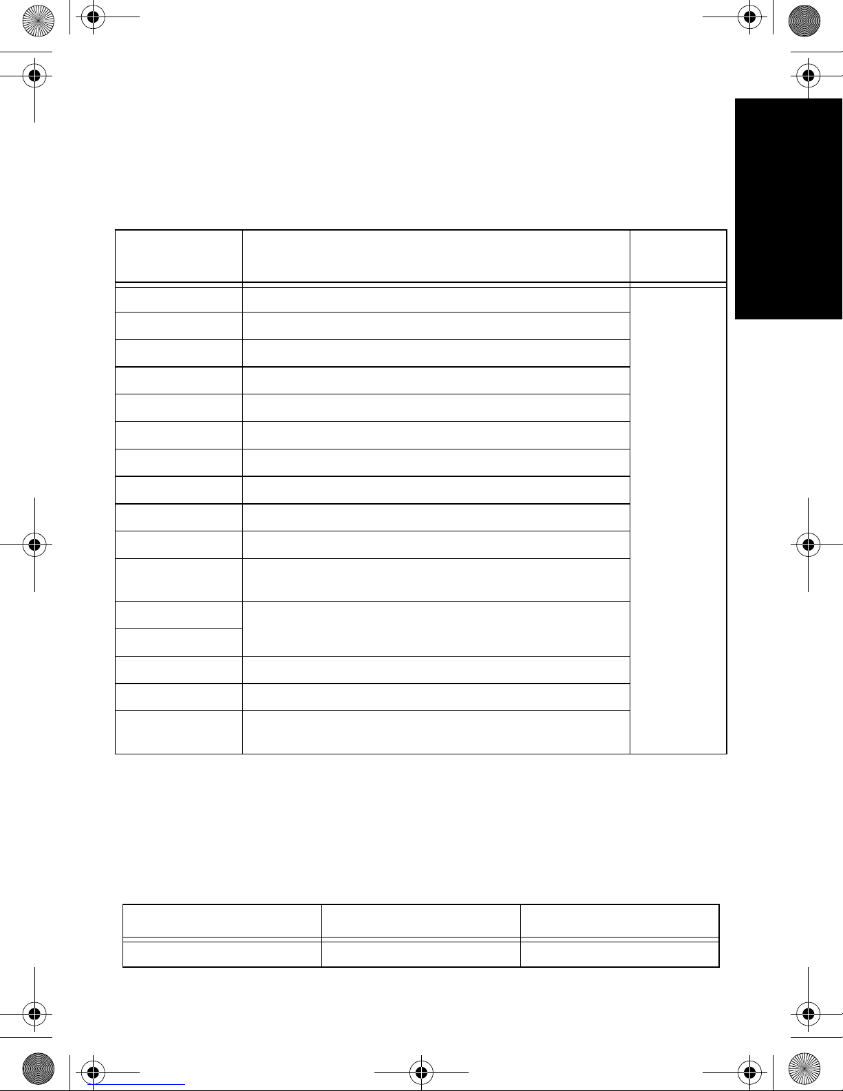
MOTOROLA AUTHORIZED BATTERIES
The following tables lists batteries that can be used with the specific subscriber
radios identified in the table title.
Table 1: Batteries for XiR P6600 / XiR P6620 Series Radios
English
Kit (part)
Number
PMNN4415 Core NiMH IP56 Battery, 1300 mAh
PMNN4416 IMPRES Li Ion Slim Battery, 1500 mAh
PMNN4417 Core Li Ion Slim Battery, 1500 mAh
PMNN4418 IMPRES Li Ion High-Capacity Battery, 2150 mAh
PMNN4406 Core Li Ion Slim Battery, 1500 mAh
PMNN4407 IMPRES Li Ion Slim Battery, 1500 mAh
PMNN4409 IMPRES Li Ion High-Capacity Battery, 2150 mAh
PMNN4412 Core NiMH Battery, 1300 mAh
NNTN8129 IMPRES Li Ion High-Capacity FM Battery, 2300 mAh
PMNN4448 IMPRES Li Ion Ultra-High-Capacity Battery, 2700 mAh
PMNN4488 IMPRES Li-Ion High-Capacity IP68 Battery for Vibrating Belt
PMNN4489 IMPRES Li Ion High-Capacity TIA4950 HazLoc IP68 Battery,
PMNN4490
Battery Chemistry / Description
Clip, 3000 mAh
2900 mAh
Charging
Pocket
NNTN8462
PMNN4491 IMPRES Li Ion Slim Battery IP68, 2100 mAh
PMNN4493 IMPRES Li-Ion High-Capacity IP68 Battery, 3000 mAh
NNTN8560 IMPRES Li Ion High-Capacity TIA4950 HazLoc Battery,
2500 mAh
AUTHORIZED POWER CORDS
This charger is designed for use in 100 VAC to 240 VAC, 50/60 Hz applications
and uses the following Motorola power cords.
Table 2: Authorized Power Cords
Plug Type Charger Kit Power Cord
No power cord / plug PMLN6621 –
3

MN000217A01.book Page 4 Thursday, October 29, 2015 12:41 PM
Table 2: Authorized Power Cords
Plug Type Charger Kit Power Cord
Taiwan PMLN6613 3004209T04
China PMLN6622 3004209T14
English
Hong Kong PMLN6618 3004209T02
Australia / New Zealand PMLN6619 3004209T07
Korea PMLN6615 3004209T13
Japan PMLN6620 3004209T15
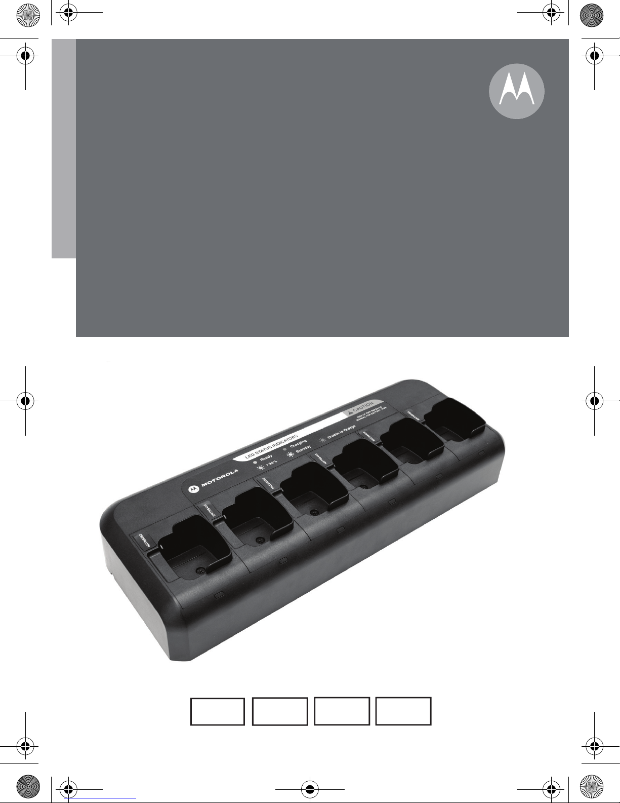
DESCRIPTION
The Multi-Unit Charger comprises a base unit which accommodates six
charging locations. Each charging location is fitted with a charging pocket.
The kit contains:
• 1 Multi-Unit Charger base unit
• 6 charging pockets
• 1 regional line cord
OPERATING INSTRUCTIONS
The Multi-Unit Charger will charge only Motorola Authorized Batteries listed in
Table 1. Other batteries may not charge. Prior to operating the charger, check
that all radio and battery inserts are in place and properly latched.
The Multi-Unit Charger can charge up to 6 radios or batteries (in any
combination) listed in Table 1.
Note: Prior to charging a battery with radio, turn the radio off.
Charging Procedure
1. Plug the charger end of the power supply cord into the power receptacle
located at the back of the charger.
2. Plug the wall receptacle end of the power supply cord into the
appropriate AC outlet. A successful power-up sequence is indicated by a
SINGLE GREEN BLINK on the charger indicator.
3. Insert a battery, or a radio with battery (radio turned off), into the
charger’s pocket by:
a. Aligning the groove on each side of the battery with the corresponding
raised rail on each side of the charger pocket.
b. Pressing the battery toward the rear of the pocket.
c. Sliding the battery into the charger pocket, ensuring complete contact
between the charger and battery contacts.
4

Charging
contacts
Charging
indicator
Power receptacle
(located here)
Charging
pocket
MN000217A01.book Page 5 Thursday, October 29, 2015 12:41 PM
4. When the battery is properly seated in the pocket, the charger indicator
will illuminate STEADY RED to indicate that the battery is charging
rapidly. When battery charging is ramping down (typically when the
battery is charged approximately 90% or greater), the charger indicator
changes to BLINKING GREEN. When the battery is nearly charged or
fully charged, the charger indicator changes to a STEADY GREEN.
5. Use two hands to remove a radio or battery from the charger pocket.
One hand to support the charger and the other hand to remove the radio
or battery.
English
Figure 1: Multi-Unit Charger
TROUBLESHOOTING
When troubleshooting, always observe the charging indicators in Table 3.
Table 3: Battery Charging Indicators
Charger Indicator Description
No indication Battery is inserted incorrectly.
Single green blink Successful charger power-up.
Blinking red Battery is unable to charge or not making proper contact.
Steady red Battery is in rapid-charge mode.
5
MN000217A01.book Page 6 Thursday, October 29, 2015 12:41 PM
Table 3: Battery Charging Indicators
Charger Indicator Description
Blinking Orange Battery is recognized by charger but is waiting to rapid
charge. (Either the battery voltage is too low, due to overdischarge, or the battery temperature is too low or too high
English
Blinking green Battery charging is tapering down (typically, when the
to allow rapid charging. When this condition is corrected, the
battery will automatically begin rapid charging).
Additional case for new ultra-high-capacity IMPRES™
Lithium-ion (Li-ion) batteries. The new ultra-high-capacity
Li-ion batteries have capacities exceeding 2000 mAh. After
approximately 15 minutes, the LED may go into a Flashing
Red mode. Remove and reinsert to get another overdischarge recovery period. This procedure may need to be
repeated several times.
battery is charged approximately 90% or greater).
Steady green Battery is nearly charged or charged.
No Charger Indication?
1. Check that the radio with battery, or the battery alone, is inserted
correctly (refer to Step 3 of "Charging Procedure").
2. Make sure that the power cord is securely plugged into the charger and
an appropriate AC outlet and that there is power to the outlet.
Blinking RED Indicator?
1. Remove the battery from the charger, and:
a. Verify that the battery is a Motorola-authorized battery listed in Table
1. Other batteries may not charge.
b. Remove power from the battery charger and using a clean dry cloth,
clean the metal charging contacts of both the battery and the charger.
2. Power up the charger and place the battery back into the charger
pocket. If the charger indicator continues to illuminate BLINKING RED
replace the battery.
Blinking ORANGE Indicator?
1. The battery temperature may be below 5 °C (41 °F) or above 40 °C
(104 °F).
2. The battery voltage may be lower than the predetermined threshold level
for rapid charging.
3. The new ultra-high-capacity Li-ion batteries have capacities exceeding
2000 mAh. After approximately 15 minutes, the LED may go into a
Flashing Red mode. Remove and reinsert to get another over-discharge
recovery period. This procedure may need to be repeated several times.
Note: Rapid charging outside of the stated temperature and voltage limits can
6
MN000217A01.book Page 7 Thursday, October 29, 2015 12:41 PM
drastically reduce the life expectancy of the battery. When this condition
is corrected, the battery will begin charging automatically (STEADY RED
indication).
CHARGING POCKET INSTALLATION
To reduce risk of electric shock, unplug the charger from the AC outlet before
removing or replacing Charging Pocket.
W A R N I N G
Removing Charging Pocket from Multi-Unit Charger
1. Remove the screw that secures the Charging Pocket to the base.
2. Lift the Charging Pocket a few inches away from the base.
3. Remove the Pocket Harness by pulling straight up on the connector
(refer to Figure 2).
Securing Charging Pocket to Multi-Unit Charger
English
1. Connect Pocket Harness by plugging in the connector to the receptacle
on Multi-Unit Charger (refer to Figure 3).
2. Slot in the Charging Pocket to the base and ensure the Charging Pocket
is flushed in to the Multi-Unit Charger. Affix the Charging Pocket screw.
7

Charging Pocket
Screw
Connector (on
charging pocket)
Receptacle (on
Multi-Unit Charger)
MN000217A01.book Page 8 Thursday, October 29, 2015 12:41 PM
English
OPTIONAL EQUIPMENT
A wall mount bracket (part number: NNTN6844) is available for the Multi-Unit
Charger. Contact your local dealer to order this item. Installation is shown
below.
Mounting Multi-Unit Charger to Wall Bracket
Figure 2: Removing Charging Pocket
Figure 3: Securing Charging Pocket to Multi-Unit Charger
8

Attach to wall in four
locations (fasteners
not provided)
M4x25 screw – two
locations (provided)
MN000217A01.book Page 9 Thursday, October 29, 2015 12:41 PM
English
Figure 4: Mounting Multi-Unit Charger to Wall Bracket
1. Mount bracket to wall using appropriate fasteners in 4 locations
(fasteners not included in kit).
2. Install two M4x25 screws (included in kit) through bracket into charger
base as shown. Do not over tighten the screws.
SERVICE
The Multi-Unit Charger is not user repairable. Replacements should be ordered
from your local dealer.
Tel: 1-800-422-4210 (US & Canada)
Tel: 1-847-538-8023 (International)
9
MN000217A01.book Page 10 Thursday, October 29, 2015 12:41 PM
English
MOTOROLA, MOTO, MOTOROLA SOLUTIONS and the Stylized M logo are trademarks or
registered trademarks of Motorola Trademark Holdings, LLC and are used under license. All
other trademarks are the property of their respective owners.
© 2014, 2015 Motorola Solutions, Inc. All rights reserved.
10
 Loading...