

Motorola solutions DTR600, DTR700 User Manual
PROFESSIONAL DIGITAL TWO-WAY RADIO
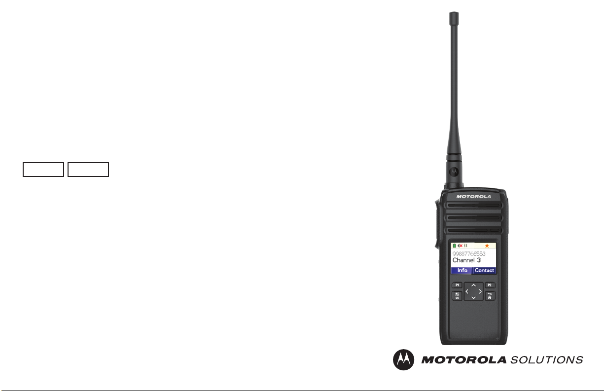
DTR600/DTR700
LIMITED KEYPAD PORTABLE RADIO
USER GUIDE
en-US
November 2018
2018 Motorola Solutions, Inc. All rights reserved.
©
fr-CA
*MN004869A01*
MN004869A01-AA

English
Contents
Product Safety and RF Exposure Compliance
Acoustic Safety....................................................5
Introduction.....................................................................6
Package Contents............................................... 6
Notice to Users (FCC and Industry Canada)..................7
Batteries and Chargers Safety Information.................... 8
Operational Safety Guidelines.............................8
Chapter 1: Radio Overview.......................................... 10
Radio Parts........................................................10
Radio Specifications.......................................... 11
Status Indicators................................................12
Display Icons.......................................... 12
Battery Features................................................ 12
About Li-Ion Battery................................ 12
Battery Recycling and Disposal.............. 13
Installing the Li-Ion Battery..................... 13
Removing the Li-Ion Battery................... 15
Holster.................................................... 16
Power Supply and Drop-In Tray SUC.....17
...............5
Battery Life..............................................18
Battery Status Information......................
Charging with the Drop-In Tray SUC...... 18
Charging a Stand-Alone Battery............. 19
Estimated Charging Time....................... 20
Charging a Radio and Battery using a
MUC........................................................20
LED Indicator of Chargers...................... 21
Chapter 2: Getting Started........................................... 23
Turning the Radio On or Off.............................. 23
Adjusting Volume...............................................23
Browsing and Selecting Channels.....................23
Chapter 3: Radio Call Features....................................25
Push-To-Talk (PTT) Button............................... 25
Talk Permit Tone (TPT)..................................... 25
Home Channel...................................................25
PROFILE ID.......................................................25
Setting the Non-Interference or Privacy
Feature................................................... 26
Talk Range........................................................ 26
Programmable Button Options.......................... 26
Private Reply..................................................... 27
18
2

English
Starting a Private Reply.......................... 27
Canceling Queues............................................. 27
Direct Call.......................................................... 27
Making a Direct Call................................28
Call All Available................................................28
Starting Call All Available........................29
Page All Available..............................................29
Starting Page All Available..................... 30
Chapter 4: Contacts Management............................... 31
Contact List........................................................31
Editing Contacts......................................31
Deleting Contacts................................... 31
Adding New Contacts............................. 32
Contacts............................................................ 32
Making Calls........................................... 32
Ending Calls............................................32
Call Log............................................................. 33
Storing Call Log...................................... 33
Chapter 5: Radio Settings............................................ 34
Adjusting Display Brightness............................. 34
Setting Backlight Timer......................................34
Setting Menu Timer........................................... 34
Enabling All Tones.............................................34
Enabling Vibrate................................................ 34
Enabling Keypad Tone...................................... 35
Enabling Power Up Tone...................................35
Selecting Mic Gain for Radio............................. 35
Selecting Mic Gain for Accessory......................35
Setting Languages.............................................36
Selecting Configuration Channel List................ 36
Chapter 6: Advanced Settings......................................37
PowerSave Mode.............................................. 37
Enabling PowerSave Mode.................... 37
Configuring the Programmable Button.............. 37
Selecting Home Channel...................................37
Chapter 7: Clone Mode................................................ 39
Cloning Radio.................................................... 39
Cloning with a MUC (Optional Accessory)........ 39
Cloning Radio Using Two SUCs and a Radioto- Radio Cloning Cable (Optional Accessory).. 41
What To Do If Cloning Fails...............................42
Cloning the Wireless PROFILE ID Number ......43
Chapter 8: Resetting to Factory Defaults..................... 45
3

English
Radio Factory Default Settings..........................45
Chapter 9: Customer Programming Software (CPS)... 46
Programming the Radio to CPS........................ 46
CPS Basic Menu Instructions............................ 46
Chapter 10: Troubleshooting........................................51
Symptoms and Solutions...................................51
Chapter 11: Use and Care........................................... 56
Chapter 12: Motorola Solutions Limited Warranty for
the United States and Canada..................................... 57
Warranty............................................................ 57
Products and Accessories................................. 57
Exclusions......................................................... 58
Software............................................................ 59
Warranty Coverage........................................... 59
How to Obtain Warranty Service or Other
Information.........................................................59
Patent Notice..................................................... 60
Export Law Assurances.....................................60
Appendix A: Accessories..............................................61
4
English
Product Safety and RF Exposure Compliance
CAUTION:
Before using this product, read the Product Safety
and RF Exposure booklet enclosed with your radio
which contains important operating instructions for
safe usage and RF energy awareness and control
for Compliance with applicable Standards and
Regulations.
For a list of Motorola Solutions-approved antennas,
batteries, and other accessories, visit the following
web site:http://www.motorolasolutions.com
Acoustic Safety
CAUTION:
Exposure to loud noises from any source for
extended periods of time may temporarily or
permanently affect your hearing. The louder the
radio volume, the less time is required before your
hearing can be affected. Hearing damage from loud
noises is sometimes undetectable at first and can
have a cumulative effect.
To protect your hearing:
• Use the lowest volume necessary to do your job.
• Increase the volume only if you are in noisy
surroundings.
• Reduce the volume before connecting headset or
earpiece.
• Limit the amount of time you use headsets or earpieces
at high volume.
• When using the radio without a headset or earpiece, do
not place the radio speaker directly against your ear.
• If you experience hearing discomfort, ringing in your
ears, or speeches that are muffled, you should stop
listening to your radio through your headset or earpiece,
and have your hearing checked by your doctor.
5

English
Introduction
This user guide covers the operation of your radios.
This radio is a product of Motorola Solutions' 80 plus years
of experience as a world leader in the designing and
manufacturing of communications equipment. This series
provides cost-effective communications for businesses
such as retail stores, restaurants, schools, construction
sites, manufacturing, property and hotel management, and
more. Motorola Solutions professional two-way radios are
the perfect communications solution for all modern fastpaced industries.
Your dealer or system administrator may have customized
your radio for your specific needs. Check with your dealer
or system administrator for more information.
NOTICE:
Read this user guide carefully to ensure that you
know how to properly operate the radio before use.
For product-related questions, contact: 1-800-448-6686 or
visit us at: http://www.motorolasolutions.com/DTR600 and
http://www.motorolasolutions.com/DTR700.
Package Contents
The following list encompasses the package content
available:
• Antenna
• Radio
• Holster
• Lithium-Ion Battery
• Power Supply
• Quick Reference Guide
• Drop-in Tray Charger
• Product Safety & RF Exposure Booklet
6
English
Notice to Users (FCC and Industry Canada)
The business two-way radios operate in the license-free
900 MHz ISM Band (902 – 928 MHz) and are subject to the
Rules and Regulations of the Federal Communications
Commission (FCC).
This device complies with Part 15 of the FCC rules and
Industry Canada's license-exempt RSS's per the following
conditions:
• This device may not cause harmful interference.
• This device must accept any interference received,
including interference that may cause undesired
operation.
• Changes or modifications made to this device, not
expressly approved by Motorola Solutions, could void
the authority of the user to operate this equipment.
To comply with FCC/IC requirements, transmitter
adjustments should be made only by or under the
supervision of a technically qualified person to perform
transmitter maintenance and repairs. Replacement of any
transmitter component such as crystal, semiconductor, and
other that are not authorized by the FCC/IC equipment
authorization for this radio violates FCC/IC rules.
NOTICE:
Use of this radio outside the country where it was
intended to be distributed is subject to government
regulations and may be prohibited.
7

English
Batteries and Chargers Safety Information
This document contains important safety and operating
instructions. Read these instructions carefully and save
them for future reference. Before using the battery charger,
read all the instructions and cautionary markings on:
• the charger
• the battery
• the radio attached with battery
• To reduce risk of injury, charge only the rechargeable
Motorola Solutions-authorized batteries. Charging the
other batteries may cause explosion, personal injury,
and damage.
• Use of accessories not recommended by Motorola
Solutions may result in fire, electric shock, or injury.
• To reduce damage to the electric plug and cord, pull by
plug rather than the cord when disconnecting the
charger.
• An extension cord should not be used unless
necessary. Use of an improper extension cord may
result in fire and electric shock. If an extension cord
must be used, make sure that the cord size is 18 AWG
for lengths up to 100 ft (30.48 m), and 16 AWG for
lengths up to 150 ft (45.72 m).
• Do not operate the charger if it has been broken or
damaged in any way. Take it to any qualified Motorola
Solutions service representatives.
• Do not disassemble the charger; it is not repairable and
replacement parts are not available. Disassembly of the
charger may result in risk of electrical shock or fire.
• To reduce risk of electric shock, unplug the charger from
the AC outlet before attempting any maintenance or
cleaning.
Operational Safety Guidelines
• Turn off the radio while charging.
• The charger is not suitable for outdoor use. Use only in
dry locations/conditions.
• Connect charger to an appropriately fused and wired
supply of the correct voltage (as specified on the
product only).
• Disconnect charger from line voltage by removing main
plug.
8

• Connect the equipment to an outlet which is easy to
access and near.
• For equipment using fuses, replacements must comply
with the type and rating specified in the equipment
instructions.
• Maximum ambient temperature around the power
supply equipment must not exceed 40 °C (104 °F).
• Power output from the power supply unit must not
exceed the ratings stated on the product label located at
the bottom of the charger.
• Make sure the cord is not stepped on, tripped over,
subjected to water, damage or stress.
English
9
1
2
3
4
5
13
11
12
10
9
8
7
6
14
English
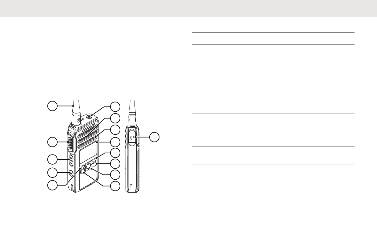
Radio Overview
This chapter explains the buttons and functions to control
the radio.
Radio Parts
This chapter describes the buttons and functions of the
radio.
Figure 1: Radio Overview
10
Table 1: Radio Parts
Label Item Description
1 Antenna Provides the needed RF
amplification when transmitting or receiving.
2 Push-To-Talk
(PTT) button
3 Volume Up/
Down Control
buttons
4 Programmable
button
Press to transmit to other
radios.
Press to adjust the volume level and to mute
the radio.
This button is field programmable by using the
Customer Programming
Software (CPS).
5 P1 button Press to select Info of
the radio.
6 Menu/OK button Press to enter Menu and
to confirm selection.
7 4-Way Naviga-
tion button
Press to toggle to the
left/right/up/down of the
selections available in
the menu.
English
Label Item Description
8 Home/Back but-
ton
9 P2 button Press to view the con-
10 Display A display that provides
11 Microphone Speak clearly into the mi-
12 Speaker Outputs all tones and au-
13 Power button Press to turn on and off
14 Audio Accessory
Connector
Press to cancel and return to a previous menu
level; press and hold to
return to Home screen.
tacts set in the radio.
visual information about
radio features.
crophone when transmitting.
dio that are generated by
the radio (for example,
keypad tones and voice
audio).
your radio.
Used to connect compat-
ible audio accessories.
Radio Specifications
The radio model is printed on the back of the radio with the
following information.
Table 2: Radio Specifications
Model Fre-
quency
Band
DTR600 ISM 900
MHz
DTR700 ISM 900
MHz
Trans-
mit
Power
(Watts)
1 30 Remov-
1 50 Remov-
Number
of
Chan-
nels
Anten-
na
able
able
11
English
Status Indicators
This chapter explains the status indicators and audio tones
used in the radio.
Display Icons
Your radio display shows icons indicate radio status.
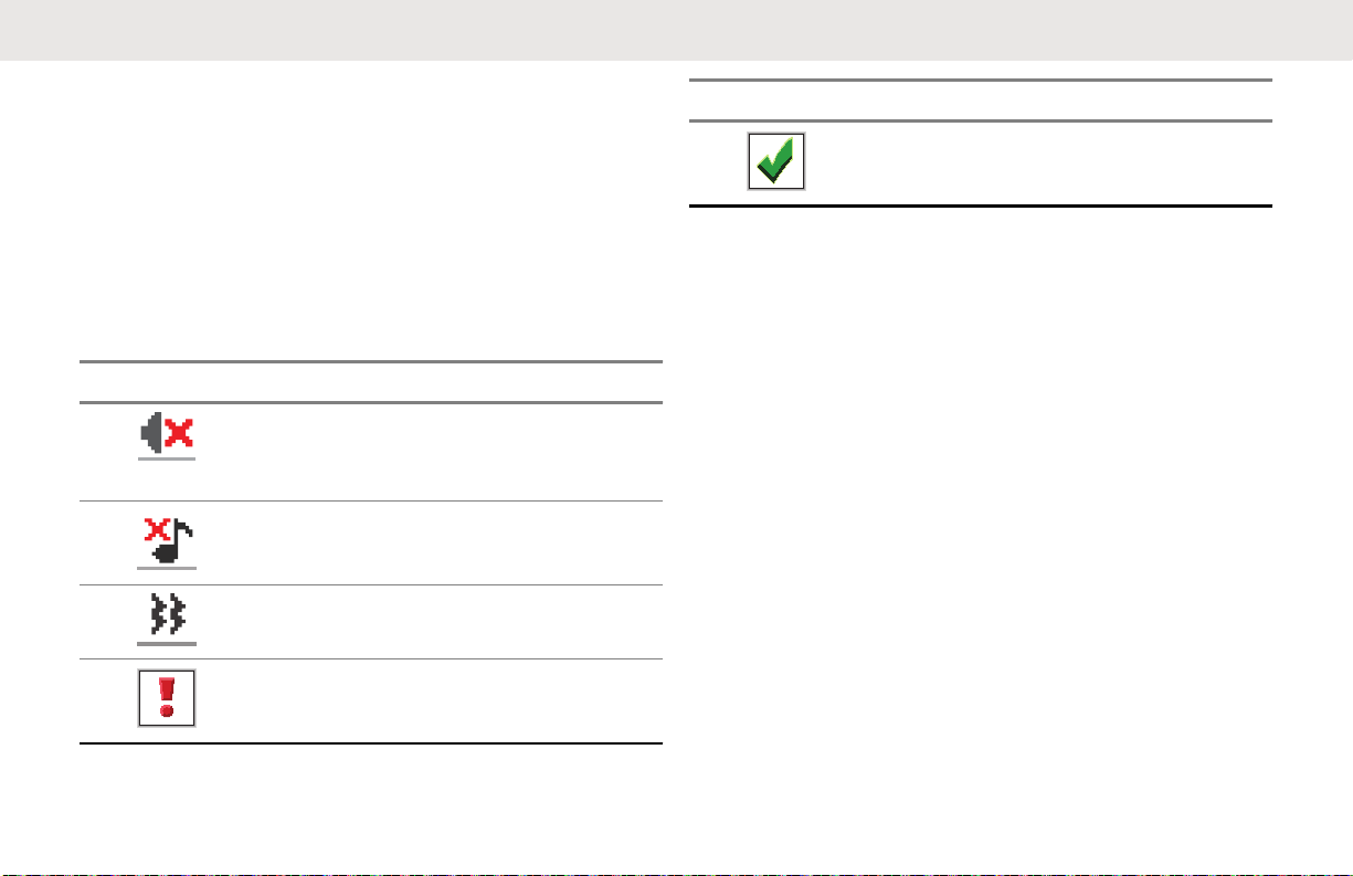
Table 3: Display Icons
Icon Description
Mute Mode
Mute Mode is enabled and
speaker is muted.
Tones Disable
Tones are turned off.
Vibrate
Vibrate mode is enabled.
Mini Negative Notice
Failed action taken.
Icon Description
Mini Positive Notice
Successful action taken.
Battery Features
The radio comes with standard Lithium-Ion (Li-Ion)
batteries.
About Li-Ion Battery
The radio comes with a rechargeable Li-Ion battery. This
battery should be fully charged before initial use to ensure
optimum capacity and performance.
Battery life is determined by several factors. The critical
ones are overcharging of batteries and the average depth
of discharge each cycle. Typically, the greater the
overcharge and the deeper the average discharge, the
fewer cycles a battery will last. For example, a battery
which is overcharged and discharged 100% for several
times a day, lasts fewer cycles than a battery that
overcharges less and is discharged to 50% per day.
Battery with minimal overcharge and has an average of
25% discharge, lasts even longer.
12

English
Motorola Solutions batteries are designed specifically to be
used with a Motorola Solutions charger and vice versa.
Charging batteries with non-Motorola Solutions equipment
may lead to battery damage and void the battery warranty.
Whenever possible, maintain the battery temperature to
77 °F (25 °C) (room temperature). Charging a cold battery
(below 50 ° F [10 °C]) may result in leakage of electrolyte
and ultimate failure of the battery. Charging a hot battery
(above 95 °F [35 °C]) results in reducing discharge capacity
and affecting the performance of the radio. Motorola
Solutions rapid-rate battery chargers contain a
temperature-sensing circuit to ensure that batteries are
charged within the temperature limits stated above.
Battery Recycling and Disposal
Li-Ion rechargeable batteries can be recycled. However,
recycling facilities may not be available in all areas. Under
various U.S. state laws and the laws of several other
countries, batteries must be recycled and cannot be
disposed of in landfills or incinerators. Contact your local
waste management agency for specific requirements and
information in your area. Motorola Solutions fully endorses
and encourages the recycling of Li-Ion batteries.
In the U.S. and Canada, Motorola Solutions participates in
the nationwide Call2Recycle program for battery collection
and recycling. Many retailers and dealers participate in this
program. For the location of the drop-off facility closest to
you, access Call2Recycle's Internet web site at https://
www.call2recycle.org/ or call 1-800-8-BATTERY. This
internet site and telephone number also provide other
useful information concerning recycling options for
consumers, businesses, and governmental agencies.
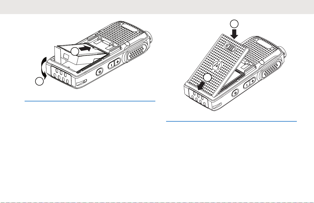
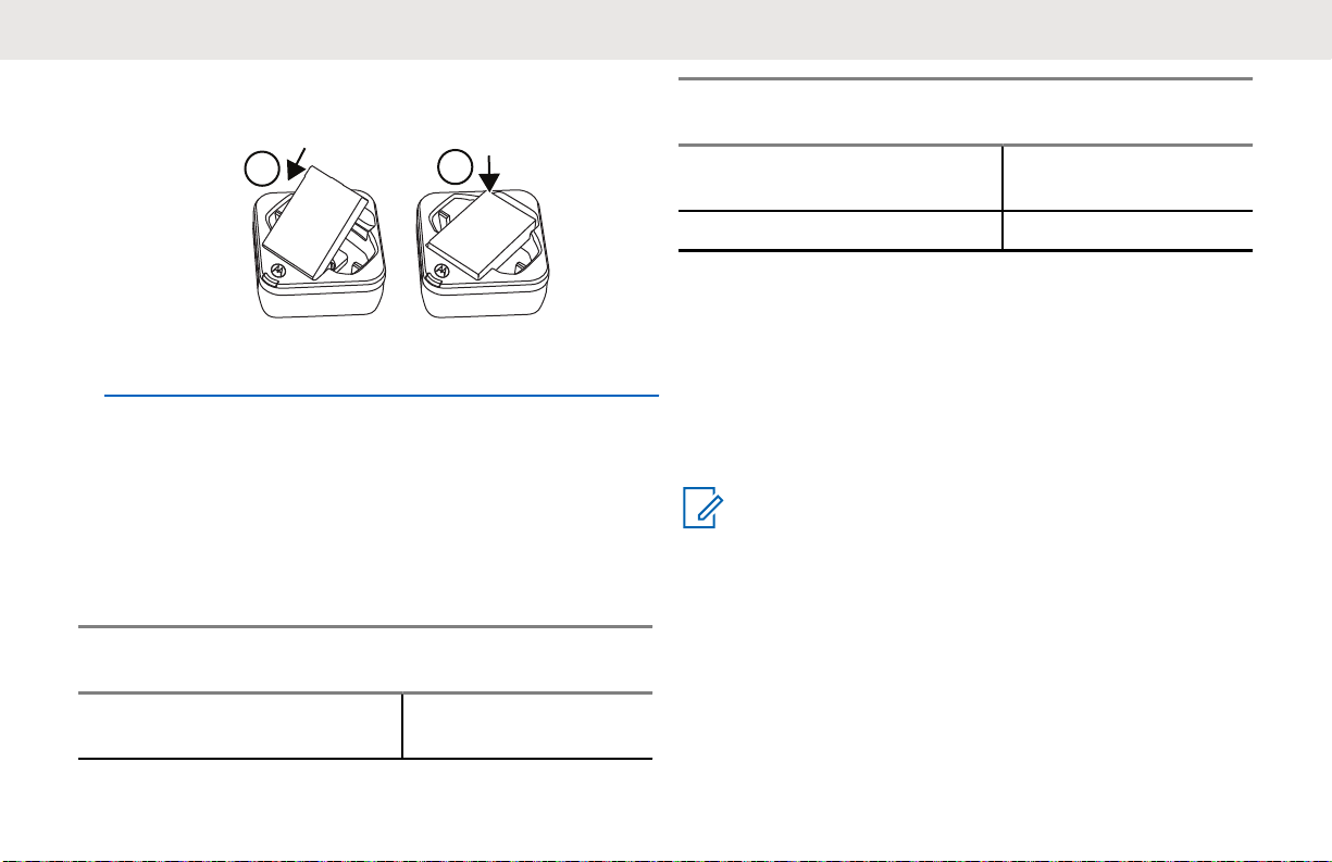
Installing the Li-Ion Battery
1 Align the battery contacts with the contacts inside
the battery compartment. Insert the contact side of
the battery first. Gently push the battery into place
and ensure the position of the battery flap is on top
of the battery.
13
1
2
2
1
English
2 To attach battery cover, align it in place and slide the
battery latch until it snaps into place.
3 Slide battery latch into lock position.
14
3
1
English
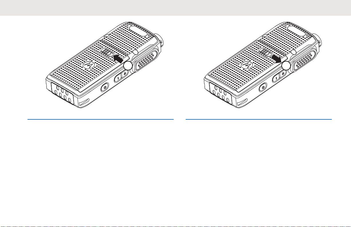
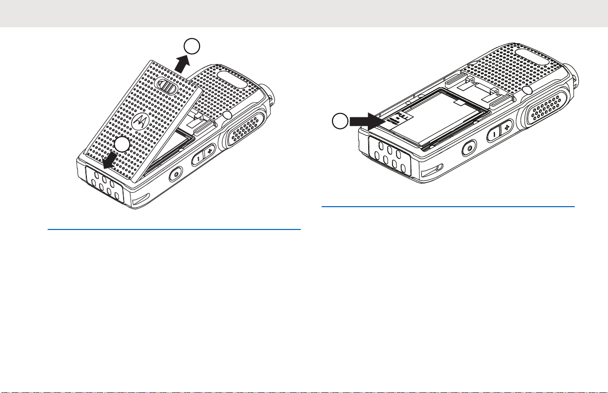
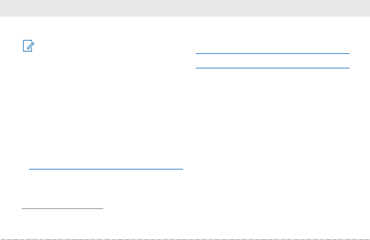
Removing the Li-Ion Battery
Ensure that the radio is turned off.
1 Move the battery latch to the unlock position.
2 Remove the battery cover by lifting the battery cover
up.
15
2
1
1
English
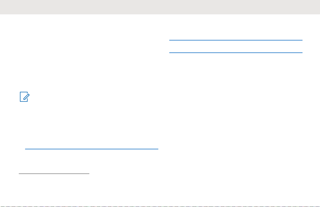
3 Pull the battery flap to remove the battery from the
radio.
Holster
The following steps explain how to use a holster.
16
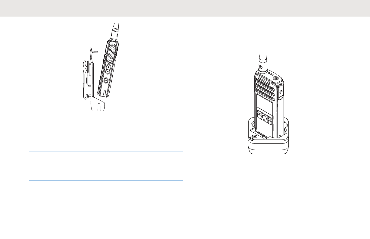
1 To insert the radio into the holster, press the radio
against the back of the holster until the hook on the
holster are inserted in the top recess.
English
Power Supply and Drop-In Tray SUC
The radio is equipped with one power supply, and one
single unit charger.
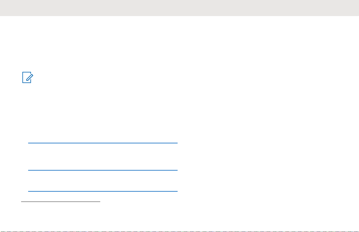
2 To remove the radio from the holster, detach the
hook of the holster from the top recess using the top
tab and slide the radio out from the holster.
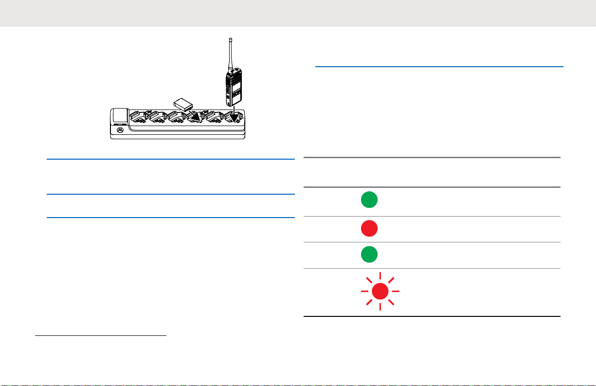
Figure 2: Charging with SUC
17
English
Battery Life
The battery lasts longer when Battery Save feature is set to
on (enabled by default).
Table 4: Li-Ion Battery Life
Battery Type Battery Save ON
Standard 16.5 hours
NOTICE:
Battery save is enabled by default. Battery life is
estimated based on 5% transmit/5% receive/90%
standby standard duty cycle.
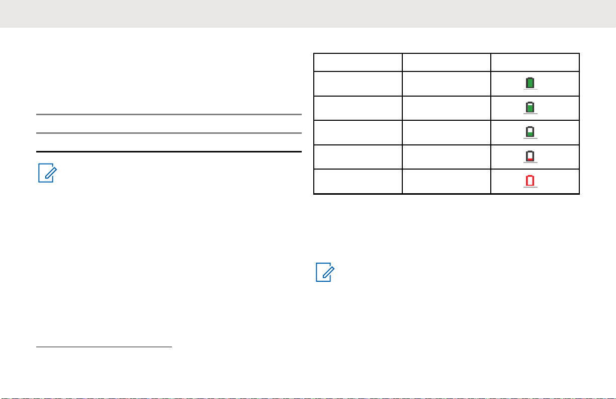
Battery Status Information
Battery status icon displays on the top left of the radio
screen.
Table 5: Battery Status
Battery Status Battery Level Battery Icon
High 71%–100%
Medium 41%–70%
Low 11%–40%
Critical 0%–10%
Shutdown
1
0%
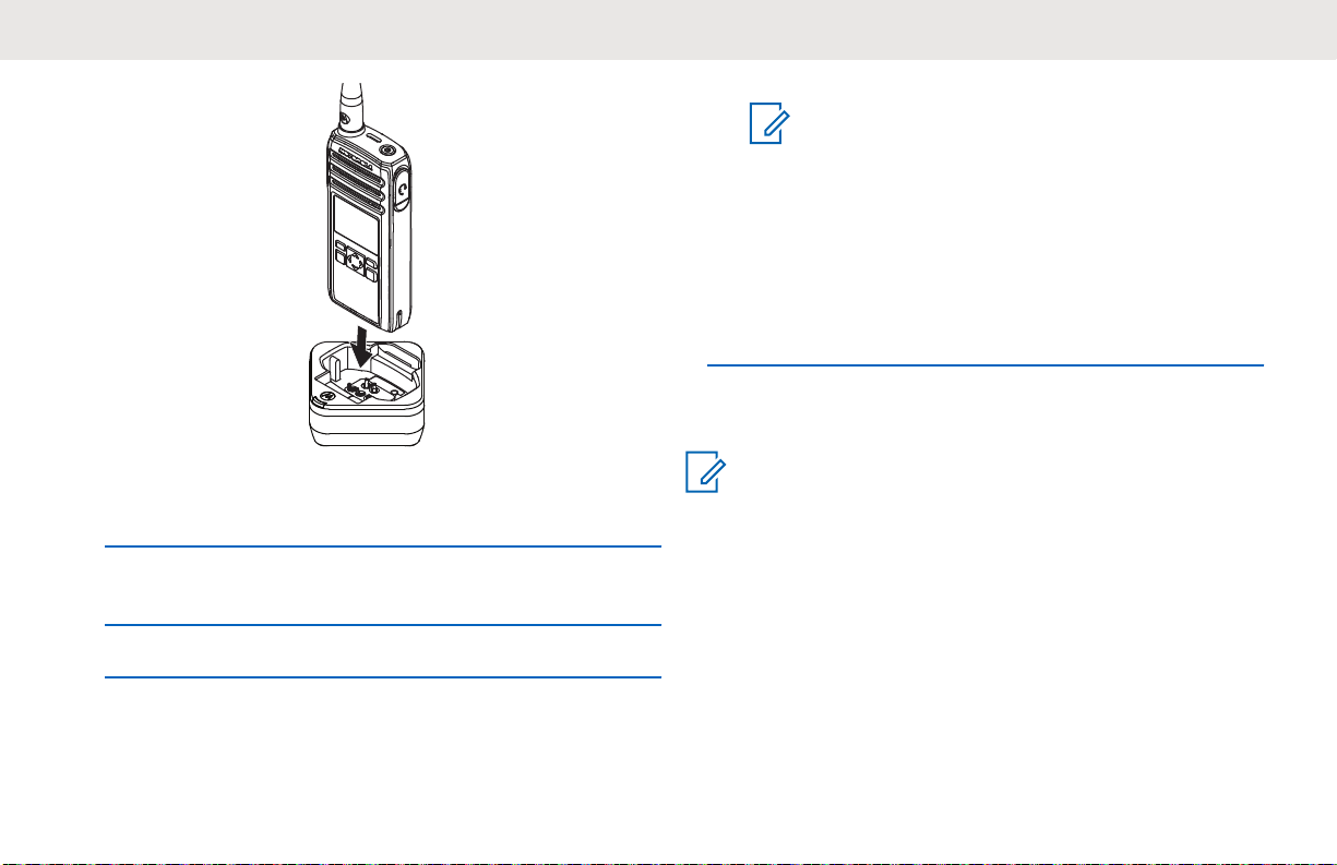
Charging with the Drop-In Tray SUC
The radio comes with a standard power supply and a
Single Unit Charger.
NOTICE:
Turn off the radio before charging and fully charge
the battery before first use. It is best to charge at
room temperature.
1
When the battery is on a Shutdown level, a continuous alert tone and automatically shutdown occurs.
18
NOTICE:
For more information, see LED Indicator of
Chargers on page 21 and Operational
Safety Guidelines on page 8.
The charger LED flashes a few times to indicate the
current battery capacity when the radio is inserted in
the tray rails. The light on the charger is red to
indicate that the battery is charging and turns green
indicates that the battery is fully charged.
Charging a Stand-Alone Battery
English
1 Place the SUC on a flat surface.
2 Insert the connector of the power supply into the port
on the side of the SUC.
3 Plug the AC adapter into a power outlet.
4 Insert the radio into the SUC with the front of the
radio facing the LED of the SUC. Ensure the radio is
securely inserted all the way into the charger.
NOTICE:
Turn off the radio before charging. For more
information, see LED Indicator of Chargers on page
21.
Insert the battery into the charging pocket with the
front of the battery facing the LED of the Single Unit
Charger (SUC).
The charger LED flashes a few times to indicate the
current battery capacity when the radio is inserted in
the tray rails. The light on the charger is red to
19
1
2
English
indicate that the battery is charging and turns green
indicates the battery is fully charged.
Figure 3: Charging a Stand-Alone Battery
Estimated Charging Time
The following table provides the estimated charging time of
the battery. For more information, see Accessories on page
61.
Table 6: Estimated Charging Time
Charging Solutions Estimated Charging
Time
Single-Unit Charger with 3 W
Power Supply
5 hours 15 minutes
Charging Solutions Estimated Charging
Time
Single-Unit Charger with 5 W
Power Supply
Multi-Unit Charger 4 hours 15 minutes
4 hours 15 minutes
Charging a Radio and Battery using a MUC
The Multi-Unit Charger (MUC) is an optional accessory and
it has six charging pockets, which allows charging up to six
radios or batteries. The batteries can be charged together
with or without the radios or placed in the MUC separately.
NOTICE:
Turn off the radios before charging and it is best to
charge at room temperature.
1 Place the MUC on a flat surface.
20
English
indicate that the battery is charging and turns green
indicates that the battery is fully charged.
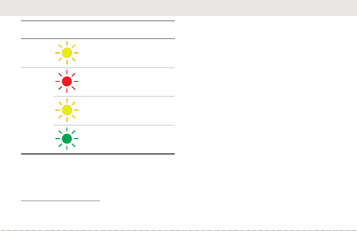
LED Indicator of Chargers
The following table explains the LED Indicator shown on
the chargers.
2 Insert the power cord plug into the dual pin
connector at the bottom of the MUC.
3 Connect the power cord into an AC outlet.
4 Insert the radio or battery into the charging pocket
with the front of the radio or battery facing the LED of
the MUC.
The charger LED flashes a few times to indicate the
current battery charge when the radio is inserted in
the tray rails. The light on the charger is red to
2
Normally, re-positioning the battery pack corrects this issue.
Table 7: Indicators
Status LED Indicator Descrip-
tion
Power
On
Green for approximately one second
-
Charging Steady red -
Charged Steady green -
2
Error
Fast-blinking red -
21
English
Status LED Indicator Descrip-
tion
Standby
Battery
Level
3
Slowly blinking amber -
Blinks red once Battery
low
Status
Blinks amber twice Battery
medium
Blinks green three
times
Battery
high
If there is no LED Indication:
• Ensure that the radio with battery, or the battery alone,
is inserted correctly.
• Ensure that the power supply cable is securely plugged
into the charger socket using the correct AC outlet and
there is power to the outlet.
• Ensure that only Motorola Solutions authorized battery
is used.
3
Battery temperature is too warm or too cold or wrong power voltage is used.
22
English
Getting Started
This section helps you to get familiar with the basic
operation of the radio.
Turning the Radio On or Off
• To turn on the radio, press and hold the Power button
until the radio vibrates and the display shows Motorola
Logo.
• To turn off the radio, press and hold the Power button
(~3 seconds) until the power down screen is shown and
the power down tone is heard.
Adjusting Volume
There are 16 increments of volume. As the (+)/(-) buttons
are pressed, you hear a beep at the current volume level. If
device is receiving during volume interaction, received
audio is heard at the new volume instead of beeps.
• Press the (+) button to increase the volume, or the (-)
button to decrease the volume,
• To mute, press, and hold the (-) button (~2 seconds)
and the display shows Mute icon.
• To unmute, press any volume button, the radio restores
the previous volume.
• To maximize the volume, press and hold the (+) button
(~2 seconds). The volume scrolls up fast to maximum
volume. You hear the volume beeps increment as the
volume increases.
NOTICE:
• Do not hold the radio too close to the ear when
the volume is high or when adjusting the volume.
• When using radio with earpiece, make sure to
adjust the radio volume to the lowest volume
before putting on the earpiece. For more
information, refer to Acoustic Safety on page 5.
Use only Motorola Solutions approved
accessories. For more information, refer to
Accessories on page 61.
Browsing and Selecting Channels
To select a channel, press the Up or Down button
on the home screen.
23
English
NOTICE:
The maximum number of characters for a
Channel Name is 12 characters.
24
English
Radio Call Features
This chapter explains all radio call features available in this
radio.
Push-To-Talk (PTT) Button
The PTT button is the primary button used to initiate voice
transmissions.
To talk, press the PTT button. A short alert tone which is
the Talk Permit Tone (TPT) sounds. Wait for the TPT tone
to end before talking. Hold the radio vertically 1 in. to 2 in.
(2.5 cm to 5 cm) from mouth when talking. Release the
PTT to listen.
While a call is not in progress, the PTT button is used to
make a new call (see Making Calls on page 32).
Talk Permit Tone (TPT)
Talk Permit Tone (TPT) is a quick distinctive double beep
tone that sounds after you press the PTT button, indicating
the channel is free to talk.
TPT is useful in ensuring orderly communications by
preventing radios from transmitting over ongoing
conversations.
NOTICE:
To ensure that your words are not cut off, always
wait for the TPT before you start to speak.
Home Channel
The Home Channel feature returns the radio to a
predefined channel, known as the home channel after a
specified idle time (see Selecting Home Channel on page
37).
Channel
The current channel that you selected to use.
PROFILE ID
Profile ID Number
The default Profile ID number for all radios is 0000. All
radios in your group have to use the same Profile ID
number in order to communicate.
25
English
To change the group Profile ID number, refer to the
Advanced Settings on page 37.
Setting the Non-Interference or Privacy Feature
This feature ensures improved private communications by
configuring an appropriate PROFILE ID number.
IMPORTANT:
By default, the PROFILE ID number is “0000”.
Ensure that all your radios are configured with the
same PROFILE ID number and is easy to
remember.
1 Press Menu/OK → Advanced → PROFILE ID.
2 Enter a four-digit radio PROFILE ID number.
Talk Range
You can communicate with a radio or a group of radios with
the same configuration.
Table 8: Talk Range
Model Steel or Con-
crete Industrial
Buildings
ISM 900 MHz Up to 350,000
ft²
Multi-Level
Buildings
Up to 30 floors
Programmable Button Options
The Programmable button comes pre-programmed with
the Private Reply feature.
By using Customer Programming Software (CPS) or the
Advanced Settings of your radio, you can also configure
the Programmable button to allow other call features, such
as Page All Available, Call All Available, Direct Call, and
Mute. You can also configure the button to disable these
options.
For more details on how to configure the Programmable
Button, refer to Configuring the Programmable Button on
page 37 or Customer Programming Software (CPS) on
page 46.
26
English
Private Reply
This feature allows two people to instantly connect privately
after a group transmission.
Push the Programmable button to capture the radio ID of
the person currently talking to your group and right after the
transmission is over, push the PTT button to talk privately
to that person.
Starting a Private Reply
The Programmable button is set to Private Reply feature
by default. This feature allows two people to instantly
connect privately after a group transmission is over.
NOTICE:
There is a channel Hangtime after a Private
transmission. By default, the Hangtime is set to 10
seconds.
1 To initiate a Private Reply, press the Programmable
button during a group call.
The display shows Private Reply On.
2 After a group call, press PTT button to call privately.
The display shows Private Reply.
3 Wait for the Talk Permit Tone to end and speak.
Canceling Queues
To exit queue mode, long press the Programmable
button.
A tone sounds. Your radio exits queue mode and
returns to the home screen.
Direct Call
The Direct Call Feature allows a user to call another predetermined user that has been mapped into the radio
Programmable button one-on-one privately (this feature
needs to be pre-programmed via CPS*).Users also have
the option to assign the Private Contact feature to any radio
channel instead of the Programmable button.This allows
the radio Programmable button to be available for other
radio features (for example: Private Reply or Mute) and
27
English
Direct Call to be set up in a special channel. (You can set
up different direct calls in different channels).
NOTICE:
To set up the Direct Call function for the first time in
your radio you must use the CPS (Customer
Programming Software) which is available for free
download at http://www.motorolasolutions.com.
Once in the CPS, you must read and upload the
radio IDs (identified in CPS as “privates”) into the
CPS in order to enable Direct Call and assign direct
calls to specific radios. For more information refer to
CPS Basic Menu Instructions on page 46.
Making a Direct Call
1 Press the Programmable button.
The display shows Direct Call Queue message
and that you are in queue.
2 To call, press the PTT button.
The distinctive Private Talk Permit Tone (TPT) is
heard.
3 Wait for the Talk Permit Tone to end and speak.
Call All Available
The Call All Available feature is functional for devices with
more than one channel.
Call All Available feature allows a communication with all
available radio users at once in a temporary “super channel
group”, without having to change through each channel
individually. Call All Available is a group call to all users
available on different channels and users who are not
currently tied up in an on-going radio conversation4.
A user who wants to respond to a Call All Available
transmission should press the PTT button before talking.
If someone initiates a Call All Available transmission, all
users engaged in the Call All Available will have their
Programmable button disabled (no Private Reply or Direct
Call are allowed during this period).
4
This feature does not interrupt ongoing communications.
28
English
The radio times out a Call All Available communication
after four seconds of inactivity. The time out prevents all
users from being tied up indefinitely in an unnecessary
group conversation. Call All Available option can be
assigned either to the Programmable button or to an extra
channel5.
Starting Call All Available
By default, the Programmable button is set to Call All
Available feature.
NOTICE:
Programmble button must be pre-programmed to
Call All Available using Advanced Settings or
Customer Programming Software (CPS).
1 Press the Programmable button.
The display shows Call All Available On,
indicating that you are in a queue.
2 When your radio is in a queue, press the PTT button.
The display shows Call All Available.
3 Wait for the Talk Permit Tone to end and speak.
Page All Available
The Page All Available feature is functional for devices with
more than one channel.
Page All Available allows a communication with all
available radio users at once without having to change
through each channel individually. Page All Available is a
one-way group voice announcement to all users on
different channels who are not currently tied up in an
ongoing radio conversation6.
A user who wants to respond to a Page All Available
transmission can reply privately by pressing the
Programmable button before talking). The Page All
Available feature prevents users from getting tied up in an
unwanted ongoing group conversation.
5
Use CPS to assign Call All Available to a specific channel.
6
This feature does not interrupt ongoing communications.
29
English
The page All Availble Mode is terminated once the PTT
button is released. Page All Available option can be
assigned either to the Programmable button or to a
channel.
Starting Page All Available
NOTICE:
Programmble button must be pre-programmed to
Page All Available using Advanced Settings or
Customer Programming Software (CPS).
1 To turn on the Page All Available feature, press the
Programmable button.
The display shows Page All Available On,
indicating that you are in queue.
2 Press the PTT button.
The display shows Page All Available.
3 Wait for the Talk Permit Tone (TPT) to end and
speak.
7
Use CPS to assign Page All Available to a specific channel.
30
 Loading...