

Motorola/Arris KVL 3000 PLUS Service Manual
© 2004 MOTOROLA, INC.
A
LL RIGHTS RESERVED
PRINTED IN U.S.A.
SERVICE MANUAL
6880802E55-O
FEBRUARY 2004
KVL 3000 PLUS™
KEY VARIABLE LOADER

COMMERCIAL WARRANTY (STANDARD)
Motorola radio communications products are warranted to be free from defects in material and workmanship for a period of ONE (1) YEAR,
(except for crystals and channel elements which are warranted for a period of ten (10) years) from the date of shipment. Parts, including crystals
and channel elements, will be replaced free of charge for the full warranty period but the labor to replace defective parts will only be provided for
One Hundred-Twenty (120) days from the date of shipment. Thereafter purchaser must pay for the labor involved in repairing the product or
replacing the parts at the prevailing rates together with any transportation charges to or from the place where warranty service is provided. This
express warranty is extended by Motorola Communications and Electronics, Inc., 1301 E. Algonquin Road, Schaumburg, Illinois 60196, to the
original purchaser only, and only to those purchasing for purpose of leasing or solely for commercial, industrial, or governmental use.
THIS WARRANTY IS GIVEN IN LIEU OF ALL OTHER WARRANTIES EXPRESS OR IMPLIED WHICH ARE
SPECIFICALLY EXCLUDED, INCLUDING WARRANTIES OF MERCHANTABILITY OR FITNESS FOR A
PARTICULAR PURPOSE. IN NO EVENT SHALL MOTOROLA BE LIABLE FOR INCIDENTAL OR
CONSEQUENTIAL DAMAGES TO THE FULL EXTENT SUCH MAY BE DISCLAIMED BY LAW.
In the event of a defect, malfunction or failure to conform to specifications established be seller, or if appropriate, to specifications accepted by
Seller in writing, during the period shown, Motorola, at its option, will either repair or replace the product or refund the purchase price thereof,
and such action on the part of Motorola shall be the full extent of Motorola's liability hereunder.
This warranty is void if:
a. the product is used in other than its normal and customary manner;
b. the product has been subject to misuse, accident, neglect or damage;
c. unauthorized alterations or repairs have been made, or unapproved parts used in the equipment.
This warranty extends only to individual products, batteries are excluded. Because each radio system is unique, Motorola disclaims liability for
range, coverage, or operation of the system as a whole under this warranty except by a separate written agreement signed by an officer of
Motorola.
LICENSED PROGRAMS—Motorola software provided in connection with this order is warranted to be free from reproducible defects for a
period of one (1) year. All material and labor to repair any such defects will be provided free of charge for the full warranty period, and SUBJECT
TO THE DISCLAIMER IN BOLD FACE TYPE.
Non-Motorola manufactured products are excluded from this warranty, but subject to the warranty provided by their manufacturers, a copy of
which will be supplied to you on specific written request.
In order to obtain performance of this warranty, purchaser must contact its Motorola salesperson or Motorola at the address first above shown,
attention Quality Assurance Department.
This warranty applies only within the United States
COMPUTER SOFTWARE COPYRIGHTS
The Motorola products described in this instruction manual may include copyrighted Motorola computer programs stored in semiconductor
memories or other media. Laws in the United States and other countries preserve for Motorola certain exclusive rights for copyrighted computer
programs, including the exclusive right to copy or reproduce in any form the copyrighted computer program. Accordingly, any copyrighted
Motorola computer programs contained in the Motorola products described in this instruction manual may not be copied or reproduced in any
manner without the express written permission of Motorola. Furthermore, the purchase of Motorola products shall not be deemed to grant either
directly or by implication, estoppel, or otherwise, any license under the copyrights, patents or patent applications of Motorola, except for the
normal non-exclusive, royalty free license to use that arises by operation of law in the sale of a product.
Document Copyrights
© 2004, Motorola, Inc. All rights reserved.
No duplication or distribution of this document or any portion thereof shall take place without the express written permission of Motorola. No par t
of this document may be reproduced, distributed, or transmitted in any form or by any means, electronic or mechanical, for any purpose without
the express written permission of Motorola.
To order additional copies of this document contact your Motorola sales representative.
Disclaimer
The information in this document is carefully examined, and is believed to be entirely reliable. However, no responsibility is assumed for
inaccuracies. Furthermore, Motorola reserves the right to make changes to any products herein to improve readability, function, or design.
Motorola does not assume any liability arising out of the applications or use of any product or circuit described herein; neither does it cover any
license under its patent rights nor the rights of others.
Trademark Information
The following are registered trademarks of Motorola, Inc.: Motorola, the Motorola logo, ASTRO.
The following are Motorola trademarks: KVL 3000 Plus.
Any other brand or product names are trademarks or registered trademarks of their respective holders.
Limitation of Liability
In no event shall Motorola be liable for special, incidental, or consequential damages (including, without limitation, loss of use, time or data,
inconvenience, commercial loss, and lost profits or savings) to the full extent that such may be disclaimed by law even if Motorola has been
advised of the possibility of such damage against licensee by any other party.

6880802E55-O FEBRUARY 2004 U.P. i
TABLE
OF
CONTENTS
. . . .
. . . . . . . . . . . . . . . . . . . . . . . . . . . . . . . . . . .
CONTENTS
ABOUT THIS MANUAL
Scope . . . . . . . . . . . . . . . . . . . . . . . . . . . . . . . . . . . . . . . . . . . . . . . . . . . . . . . . . . . . . . . . . . . . . . . . . . . . . . . .iii
How the Manual Is Organized . . . . . . . . . . . . . . . . . . . . . . . . . . . . . . . . . . . . . . . . . . . . . . . . . . . . . . . . . . . .iii
Related Manuals . . . . . . . . . . . . . . . . . . . . . . . . . . . . . . . . . . . . . . . . . . . . . . . . . . . . . . . . . . . . . . . . . . . . . . .iii
Error and Concerns Reporting. . . . . . . . . . . . . . . . . . . . . . . . . . . . . . . . . . . . . . . . . . . . . . . . . . . . . . . . . . . . .iii
How to Order Parts . . . . . . . . . . . . . . . . . . . . . . . . . . . . . . . . . . . . . . . . . . . . . . . . . . . . . . . . . . . . . . . . . . . . .iv
How to Return Parts for Repair. . . . . . . . . . . . . . . . . . . . . . . . . . . . . . . . . . . . . . . . . . . . . . . . . . . . . . . . . . . . v
CHAPTER 1: SPECIFICATIONS
Service and Replacement Modules . . . . . . . . . . . . . . . . . . . . . . . . . . . . . . . . . . . . . . . . . . . . . . . . . . . . . . . . . . . . . . .1-1
Accessories . . . . . . . . . . . . . . . . . . . . . . . . . . . . . . . . . . . . . . . . . . . . . . . . . . . . . . . . . . . . . . . . . . . . . . . . . . . . . . . . .1-2
Performance Specifications . . . . . . . . . . . . . . . . . . . . . . . . . . . . . . . . . . . . . . . . . . . . . . . . . . . . . . . . . . . . . . . . . . . . .1-3
User Interface . . . . . . . . . . . . . . . . . . . . . . . . . . . . . . . . . . . . . . . . . . . . . . . . . . . . . . . . . . . . . . . . . . . . . . . .1-5
Regulatory Compliance and Approvals . . . . . . . . . . . . . . . . . . . . . . . . . . . . . . . . . . . . . . . . . . . . . . . . . . . .1-5
Electromagnetic Compatibility . . . . . . . . . . . . . . . . . . . . . . . . . . . . . . . . . . . . . . . . . . . . . . . . . . . . . . . . . . .1-5
Environmental Testing . . . . . . . . . . . . . . . . . . . . . . . . . . . . . . . . . . . . . . . . . . . . . . . . . . . . . . . . . . . . . . . . .1-6
CHAPTER 2: BLOCK DIAGRAM THEORY
Power Block. . . . . . . . . . . . . . . . . . . . . . . . . . . . . . . . . . . . . . . . . . . . . . . . . . . . . . . . . . . . . . . . . . . . . . . . . . . . . . . . .2-1
Overview . . . . . . . . . . . . . . . . . . . . . . . . . . . . . . . . . . . . . . . . . . . . . . . . . . . . . . . . . . . . . . . . . . . . . . . . . . . .2-1
Voltage Detectors . . . . . . . . . . . . . . . . . . . . . . . . . . . . . . . . . . . . . . . . . . . . . . . . . . . . . . . . . . . . . . . . . . . . .2-1
Processor Block . . . . . . . . . . . . . . . . . . . . . . . . . . . . . . . . . . . . . . . . . . . . . . . . . . . . . . . . . . . . . . . . . . . . . . . . . . . . . .2-4
Overview . . . . . . . . . . . . . . . . . . . . . . . . . . . . . . . . . . . . . . . . . . . . . . . . . . . . . . . . . . . . . . . . . . . . . . . . . . . .2-4
Processor . . . . . . . . . . . . . . . . . . . . . . . . . . . . . . . . . . . . . . . . . . . . . . . . . . . . . . . . . . . . . . . . . . . . . . . . . . . .2-4
32.768 kHz Oscillator (Y300). . . . . . . . . . . . . . . . . . . . . . . . . . . . . . . . . . . . . . . . . . . . . . . . . . . . . . . . . . . .2-5
Target Interface . . . . . . . . . . . . . . . . . . . . . . . . . . . . . . . . . . . . . . . . . . . . . . . . . . . . . . . . . . . . . . . . . . . . . . .2-5
Memory Block. . . . . . . . . . . . . . . . . . . . . . . . . . . . . . . . . . . . . . . . . . . . . . . . . . . . . . . . . . . . . . . . . . . . . . . . . . . . . . .2-5
User Interface Block . . . . . . . . . . . . . . . . . . . . . . . . . . . . . . . . . . . . . . . . . . . . . . . . . . . . . . . . . . . . . . . . . . . . . . . . . .2-6
Numeric Keypad . . . . . . . . . . . . . . . . . . . . . . . . . . . . . . . . . . . . . . . . . . . . . . . . . . . . . . . . . . . . . . . . . . . . . . . . . . . . .2-6
Control Keypad . . . . . . . . . . . . . . . . . . . . . . . . . . . . . . . . . . . . . . . . . . . . . . . . . . . . . . . . . . . . . . . . . . . . . . . . . . . . . .2-6
Display Control Circuitry . . . . . . . . . . . . . . . . . . . . . . . . . . . . . . . . . . . . . . . . . . . . . . . . . . . . . . . . . . . . . . . . . . . . . .2-7
PCMCIA Block . . . . . . . . . . . . . . . . . . . . . . . . . . . . . . . . . . . . . . . . . . . . . . . . . . . . . . . . . . . . . . . . . . . . . . . . . . . . . .2-7
Real Time Clock Block . . . . . . . . . . . . . . . . . . . . . . . . . . . . . . . . . . . . . . . . . . . . . . . . . . . . . . . . . . . . . . . . . . . . . . . .2-8
Communications Block . . . . . . . . . . . . . . . . . . . . . . . . . . . . . . . . . . . . . . . . . . . . . . . . . . . . . . . . . . . . . . . . . . . . . . . .2-8
Encryption Block. . . . . . . . . . . . . . . . . . . . . . . . . . . . . . . . . . . . . . . . . . . . . . . . . . . . . . . . . . . . . . . . . . . . . . . . . . . . .2-8

ii 6880802E55-O FEBRUARY 2004
CONTENTS
CHAPTER 3: MAJOR SIGNAL DESCRIPTIONS
Bus/Processor Control Lines . . . . . . . . . . . . . . . . . . . . . . . . . . . . . . . . . . . . . . . . . . . . . . . . . . . . . . . . . . . . . . . . . . . 3-1
Serial Peripheral Interface (SPI) . . . . . . . . . . . . . . . . . . . . . . . . . . . . . . . . . . . . . . . . . . . . . . . . . . . . . . . . . . . . . . . . 3-3
Serial Communication Interface (SCI) . . . . . . . . . . . . . . . . . . . . . . . . . . . . . . . . . . . . . . . . . . . . . . . . . . . . . . . . . . . 3-3
Target Interface Signals . . . . . . . . . . . . . . . . . . . . . . . . . . . . . . . . . . . . . . . . . . . . . . . . . . . . . . . . . . . . . . . . . . . . . . . 3-3
Encryption Interface Signals . . . . . . . . . . . . . . . . . . . . . . . . . . . . . . . . . . . . . . . . . . . . . . . . . . . . . . . . . . . . . . . . . . . 3-4
Miscellaneous Signals . . . . . . . . . . . . . . . . . . . . . . . . . . . . . . . . . . . . . . . . . . . . . . . . . . . . . . . . . . . . . . . . . . . . . . . . 3-5
CHAPTER 4: DISASSEMBLY INSTRUCTIONS
CHAPTER 5: TROUBLESHOOTING
Introduction . . . . . . . . . . . . . . . . . . . . . . . . . . . . . . . . . . . . . . . . . . . . . . . . . . . . . . . . . . . . . . . . . . . . . . . . . . . . . . . . 5-1
Troubleshooting Procedures . . . . . . . . . . . . . . . . . . . . . . . . . . . . . . . . . . . . . . . . . . . . . . . . . . . . . . . . . . . . . . . . . . . 5-1
Parts List, CLN7493D KVL 3000 Plus Main Board . . . . . . . . . . . . . . . . . . . . . . . . . . . . . . . . . . . . . . . . . . . . . . . . . 5-5
Foldout Diagrams. . . . . . . . . . . . . . . . . . . . . . . . . . . . . . . . . . . . . . . . . . . . . . . . . . . . . . . . . . . . . . . . . . . . . . . . . . . . 5-7
APPENDIX A: ERROR MESSAGES

6880802E55-O FEBRUARY 2004 iii
ABOUT
THIS
MANUAL
. . . .
. . . . . . . . . . . . . . . . . . . . . . . . . . . . . . . . . . .
ABOUT THIS MANUAL
SCOPE
This manual is intended for use by experienced technicians familiar with similar types of
equipment. This manual contains detailed servicing information (including schematics, circuit
board details, and parts lists) sufficient to allow service personnel to make component-level
repairs. Technicians should understand encryption concepts and be familiar with other types of
Motorola encryption equipment.
The information in this manual is current as of the printing date. Changes which occur after the
printing date are incorporated by Instruction Manual Revisions (SMR). These SMRs are added
to the manuals as the engineering changes are incorporated into the equipment.
HOW THE MANUAL IS ORGANIZED
This manual is a combination of descriptive information and procedural instructions describing
tasks associated with troubleshooting and repairing the device. The manual includes
troubleshooting information, schematic diagrams, component location diagrams, instructions on
replacing major subassemblies, and replacement parts information.
RELATED MANUALS
The following manuals may be required to supplement the information contained in this guide:
• Dimetra KVL 3000 Plus™ User’s Guide — 6881131E52
• ASTRO
®
25 KVL 3000 Plus™ User’s Guide — 6881132E29
ERROR AND CONCERNS REPORTING
Any errors or concerns about this manual or its contents should be addressed to KVL 3000 Plus
Brand Manager and faxed to 1-847-435-9067. Include your name and phone number so we can
follow up with you.

iv 6880802E55-O FEBRUARY 2004
ABOUT THIS MANUAL
HOW TO ORDER PARTS
For complete information on ordering replacement modules, contact the appropriate Motorola
Accessories and Aftermarket Division facility listed below.
UNITED STATES AND CANADA
Mail Motorola, Inc.
Accessories and Aftermarket Division
1309 East Algonquin Road
Schaumburg, IL 60196
Phone (800) 422-4210
(847) 538-8023 (Outside the U.S.)
FAX (800) 622-6210
(847) 576-3023 (Outside the U.S.)
UNITED STATES FEDERAL GOVERNMENT
Mail Motorola, Inc.
Accessories and Aftermarket Division
1309 East Algonquin Road
Schaumburg, IL 60196
Phone (800) 826-1913
FAX (410) 712-6033
EUROPE, MIDDLE EAST, AND AFRICA
Mail Euro Repair And Service Centre
Motorola GmbH,
Customer Care
Am Borsigturm 130
13507 Berlin
Germany
Phone +49 30 6686 1555
LATIN AMERICA AND SOUTH AMERICA
Mail LACR Parts Division
Motorola, Inc.
Attn.: Octavio Cadena
789 International Parkway
Sunrise, FL 33325
Phone (954) 723-6531
FAX (954) 723-8560

6880802E55-O FEBRUARY 2004 v
KVL 3000 PLUS™ KEY VARIABLE LOADER SERVICE MANUAL ABOUT THIS MANUAL
HOW TO RETURN PARTS FOR REPAIR
For instructions on returning faulty modules for repair, contact the System Support Center at:
Motorola System Support Center
1311 E. Algonquin Road
Schaumburg, IL 60196
1-800-221-7144
1-847-576-7300 (outside the U.S.)
1-847-576-2172 (FAX)

vi 6880802E55-O FEBRUARY 2004
ABOUT THIS MANUAL
THIS PAGE INTENTIONALLY LEFT BLANK.

6880802E55-O FEBRUARY 2004 1-1
CHAPTER
1
. . . .
. . . . . . . . . . . . . . . . . . . . . . . . . . . . . . . . . . .
SPECIFICATIONS 1
. . . . . . . . . . . . . . . . . . . . . . . . . . . . . . . . . . .
. .
SERVICE AND REPLACEMENT MODULES
The field replaceable units (FRUs) available for the KVL 3000 Plus Key Variable Loader are
listed in Table 1-1.
The model numbers for replacement parts available for the KVL 3000 Plus Key Variable Loader
are listed in Table 1-2.
T
ABLE 1-1 KVL 3000 PLUS FRUS
Item Description
DLN1193 KVL 3000 Plus Display Board
CLN1385 KVL 3000 Plus PCMCIA Board
CLN1386 KVL 3000 Plus Power Board
DLN1194 KVL 3000 Plus Housing Kit
DLN1222 KVL 3000 Plus Main Board
T
ABLE 1-2 MODEL COMPLEMENT FOR T6717A KVL 3000 PLUS
Item Description
CLN7493 KVL 3000 Plus Main Circuit Board
CLN7722 KVL 3000 Plus Bitmapped Display
CLN7064 Chassis Assembly
CLN7724 Housing Assembly
CLN6985 Hardware

1-2 6880802E55-O FEBRUARY 2004
ACCESSORIES CHAPTER 1: SPECIFICATIONS
. . . . . . . . . . . . . . . . . . . . . . . . . . . . . . . . . . .
. .
ACCESSORIES
CLN7135 Nameplate
CNN6002 Coin Cell Battery
NTN7395 High Capacity NiCad Battery
CBN6134 Packing
CLN7751 KVL 3000 Plus Bracket Stand
6881132E29
6881131E52
ASTRO
®
25 KVL 3000 Plus™ User’s Guide
Dimetra KVL 3000 Plus™ User’s Guide
T
ABLE 1-3 BATTERY ACCESSORIES
Item Description
NTN1402 120 Volt Rapid Rate Dual Unit Charger
NTN7621 120 Volt Rapid Rate Multi Unit Charger
NTN1403 220 Volt Rapid Rate Multi Unit Charger
NTN1404 240 Volt Rapid Rate Multi Unit Charger
NTN7395 High Capacity Nickel Cadmium Battery
T
ABLE 1-4 INTERFACE CABLES AND ACCESSORIES
Kit Option Description
CKN6766 N/A KVL Dimetra Adapter
Use with CKN6767A for TETRA Site Controller, Base Radio
Controller, Mobile Subscriber
CKN6767 N/A KVL Dimetra Serial Cable
Use for Authentication Centre, Provisioning Centre, Zone
Controller
TDN9390 C724AA MTS 2000™, XTS 3000™, MTS2500, MTS5000, XTS5000
TKN8209 C540AA MTX300S and STX Series
T
ABLE 1-2 MODEL COMPLEMENT FOR T6717A KVL 3000 PLUS (CONTINUED)
Item Description

6880802E55-O FEBRUARY 2004 1-3
KVL 3000 PLUS™ KEY VARIABLE LOADER SERVICE MANUAL PERFORMANCE SPECIFICATIONS
. . . . . . . . . . . . . . . . . . . . . . . . . . . . . . . . . . .
. .
PERFORMANCE SPECIFICATIONS
TKN8210 C541AA MICOR™ mobile and base, portable repeater
TKN8229 C542AA Series II CIU, SYNTOR™, SYNTOR X™, MCX 1000™,
PX300-S™, KMC
TKN8506 C544AA Saber™, ASTRO Saber™
TKN8531 C543AA MSF 5000, DIU, DIU 3000, Expo, SYNTOR X 9000™
Series, RNC, SPECTRA™, ASTRO SPECTRA™ (requires
TRN7414), Motorola Gold Elite Gateway (MGEG),
XTL 5000
TKN9152 C551AA MCS 2000™
TRN7414 N/A Cable Adapter for SPECTRA, ASTRO SPECTRA, and
XTL 5000
CKN6324 N/A KVL 3000 Plus DB-9/Modem Cable
N/A C954AB Cables for SPECTRA and ASTRO SPECTRA
(includes cable and adapter)
T
ABLE 1-5 PHYSICAL SPECIFICATIONS
Item Specification
Dimensions 226 mm L (includes Connector Boot)
89 mm W
48 mm Thick (High Capacity Battery Included)
Weight 714 g (High Capacity Battery Included)
T
ABLE 1-6 GENERAL SPECIFICATIONS
Item Specification
Motorola 68332 Processor: 16.78 MHz (32.768 kHz Oscillator)
Code Space 2M x 8 Flash Memory
Key and Key Data Storage 128K x 8 EEPROM
T
ABLE 1-4 INTERFACE CABLES AND ACCESSORIES (CONTINUED)
Kit Option Description

1-4 6880802E55-O FEBRUARY 2004
PERFORMANCE SPECIFICATIONS CHAPTER 1: SPECIFICATIONS
Operating Memory 512K x 8 RAM
Tamper Protection
Tone Generator
Real Time Clock
Power Regulation Continuous Power Regulation
Switched Power Regulation
Low Voltage Detection Low Battery Detection (<6.68V)
Minimum Voltage to Upgrade KVL (7.24V)
5 V Detection
Backup Power 3 Volt Coin Cell Battery for Real Time Clock Backup
PCMCIA Support Interface support for Type I or Type II PCMCIA Cards
Serial Communications RS232 Port
T
ABLE 1-7 ENCRYPTION SPECIFICATIONS
Item Specification
Supported Encryption
Applications:
•DES-CFB
•DES-XL
•DES-OFB
• DVP-XL
• DVI-XL
•AES
• ADP
Supported Encryption
Protocols:
• 12 kbps SECURENET
• 9.6 kbps Secure ASTRO (VSELP Vocoder)
• 9.6 kbps Secure APCO Project 25 (IMBE Vocoder)
Encryption Keys: 1,024 Total Traffic and Shadow Keys
Standards: • FIPS 46-2
•FIPS 81
• FIPS 140-2 (pending certification)
T
ABLE 1-6 GENERAL SPECIFICATIONS (CONTINUED)
Item Specification

6880802E55-O FEBRUARY 2004 1-5
KVL 3000 PLUS™ KEY VARIABLE LOADER SERVICE MANUAL PERFORMANCE SPECIFICATIONS
USER INTERFACE
• Bitmapped LCD Display
• LCD Annunciator Line
• 4x4 Numeric Keypad (0 - 9 and A - F keys)
• Two General purpose softkeys
• Scroll Left/Increment Key
• Scroll Right/Decrement Key
• Power On/Off (
PWR) DELETE/SHIFT, ENTER, Esc Keys
• DB-9 Connector (RS232)
• Type II PCMCIA Slot
• Keyload Port
REGULATORY COMPLIANCE AND APPROVALS
Safety: EN 6095
ELECTROMAGNETIC COMPATIBILITY
• CISPR 22 Class A
• European EMC Directive 89/336 EEC
• EN 50022 Class A
• EN 55024
• IEC 801.2, IEC 801.3, IEC 801.4, IEC 61000-4.2, IEC 61000-4.3
• FCC Part 15*
* This equipment has been tested and found to comply with the limits for a Class A digital
device, pursuant to Part 15 of the FCC Rules. These limits are designed to provide reasonable
protection against harmful interference when the equipment is operated in a commercial
environment. This equipment generates, uses, and can radiate radio frequency energy and, if not
installed and used in accordance with the instruction manual, may cause harmful interference to
radio communications. Operation of this equipment in a residential area is likely to cause
harmful interference in which case the user will be required to correct the interference at his own
expense.

1-6 6880802E55-O FEBRUARY 2004
PERFORMANCE SPECIFICATIONS CHAPTER 1: SPECIFICATIONS
ENVIRONMENTAL TESTING
TABLE 1-8 ENVIRONMENTAL TESTING STANDARDS AND COMPLIANCE
Standard Method Procedure Test Performance
MIL-STD 810E 516.4 I Thermal Shock Meets or exceeds published specs following
shock testing.
MIL-STD 810E 516.4 I Vibration Meets or exceeds published specs following
vibration testing.
MIL-STD 810E 505.3 I Solar Radiation Meets or exceeds published specs following
solar radiation testing.
MIL-STD 810E 510.3 I Blowing Dust Meets or exceeds published specs following
blowing dust testing.
Operating
Temperature
-30° to +60° Celsius except PCMCIA Card
(which is 0° to +60° Celsius)
Storage
Temperature
-55° to +85° Celsius

6880802E55-O FEBRUARY 2004 2-1
CHAPTER
2
. . . .
. . . . . . . . . . . . . . . . . . . . . . . . . . . . . . . . . . .
BLOCK DIAGRAM THEORY 2
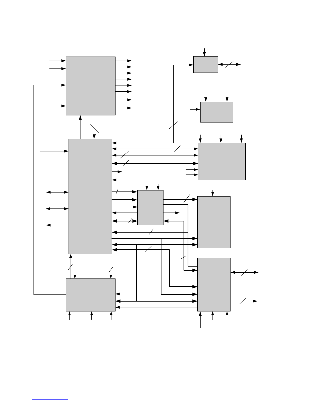
This chapter describes the KVL 3000 Plus circuitry at a block diagram level. See Figure 2-1 for the block
diagram. The service diagrams provided in Chapter 5 are also referenced throughout the theory.
. . . . . . . . . . . . . . . . . . . . . . . . . . . . . . . . . . .
. .
POWER BLOCK
OVERVIEW
The power block (see Figure 5-6) consists of all the circuitry used to control the power into the
KVL 3000 Plus. Main board power is provided by the main battery through the power circuit board and
the power flex cable. Backup battery power for the Real Time Clock is provided by the 3.0 Volt coin cell
battery.
The applied voltage from the main battery is fed initially into 3 voltage detectors (Low Upgrade, Low
Battery, and Low Voltage) and 2 regulators (5V Continuous Regulator and 5V Switched Regulator). The
output from 5V Continuous Regulator is fed into a 3.3V Continuous Regulator. The output from the
5V Switched Regulator is fed into a 3.3V Switched Regulator and a 2.8V Switched Regulator.
VOLTAGE DETECTORS
All detectors on the KVL board are 2.3V detectors. Prior to reaching the detector, the input voltage is
passed through a resistor network to drop the voltage into a range suitable for the detector. To disable the
functionality of the voltage detectors when the KVL is powered off, the input voltage is also passed
through a switching logic circuit before going through the resistor network. To reduce current
consumption when the KVL is powered off, the switching logic circuit prevents the KVL from checking
the battery level when the unit is powered off.
• Low Upgrade Voltage Detector
The output from low voltage detector U508 (PROG_VOLT_LOW*) is fed into one of the
TPU channels on the processor (TPU7). If the input voltage drops below a certain set level
(~7.24V), the processor reads a low signal from TPU7 and the processor uses this
information to prohibit a KVL upgrade from being executed.
2-2 6880802E55-O FEBRUARY 2004
POWER BLOCK CHAPTER 2: BLOCK DIAGRAM THEORY
FIGURE 2-1 OVERALL BLOCK DIAGRAM
POWER
PROCESSOR
USER
INTERFACE
(KEYPAD, DISPLAY,
TONE GEN)
PCMCIA
RTC
COM M
7.5 VDC
3.0 VDC
PWR_SWITCH*
uP_Control*
3
PROG_VOLT_LOW*
LOW_BATTERY *
5V_DETECT*
CONT_5V
CONT_3.3V
SW_5V
SW_3.3V
SW_2.8V
SW_2.8VSW_5VCONT_5V
BATT_3V
ARMOR_TAMPER*
ARMOR_ERASE*
RS232
SCI
SPI
BATT_3V SW_5V
MEMORY
(FLASH,
EEPROM,
RAM)
CPLD
(CS LOGIC,
HW ID,
CLK DIV,
68332 <-> ISA
DATA LINES (D0 thru D15)
ADDRESS LINES (A0 thru A18)
(A16-A22)
MEMORY CHIP
SELECT S
ENCRYPTION
(ARMOR)
ENCRYPTION I C CONTROL
ARMOR_TAMPER*
ARMOR_ERASE*
(D8-D15)
(D0-D15)
(A0-A18)
SPKROUT
PCMCIA
CONTR OL S
PCMCIA
LOGIC
INTERFACE
PCMCIA
PO W E R
INTERFACE
(D8-D15)
TAMPER_SW_OPEN
CS_KEY_WRITE*
(For Keypad and
Tone Gen Ctrl)
DISPLA Y
CONTROL
USER
INTERFACE
INTERRUPTS
SW_5V
SW_5V
CTRL
SW_5V
DSACK
CONT_3.3V SW_3.3V SW_5V
SW_5VTARGET_K_Fb
TARGET_KID
TARGET_WE
ARMOR SC I
CLKOUT
(16.7 MHz)
(8 MHz - from the
CLK DIV Block)
6
3
2
2
4
2
6
CLKOUT
12
8
58
6
2
4
(A0-A7)
(8 MHz)
HWID_CLK
HWID
ISA
SIGNALS
68332
SIGNALS
7
3
SW_3.3V
SW_3.3V
 Loading...