


FCC RF Test Report
Report No. : FR693004C
FCC RF Test Report
APPLICANT : Motorola Mobility LLC
EQUIPMENT : Mobile Cellular Phone
BRAND NAME : Motorola
MODEL NAME : 9369, 9847
FCC ID : IHDT56VF2
STANDARD : FCC Part 15 Subpart C §15.247
CLASSIFICATION : (DTS) Digital Transmission System
The product was received on Sep. 30, 2016 and testing was completed on Oct. 17, 2016. We,
SPORTON INTERNATIONAL (KUNSHAN) INC., would like to declare that the tested sample
has been evaluated in accordance with the test procedures and has been in compliance
with the applicable technical standards.
The test results in this report apply exclusively to the tested model / sample. Without written
approval of SPORTON INTERNATIONAL (KUNSHAN) INC., the test report shall not be
reproduced except in full.
Prepared by: James Huang / Manager
Approved by: Jones Tsai / Manager
SPORTON INTERNATIONAL (KUNSHAN) INC.
No. 3-2, PingXiang Road, Kunshan, Jiangsu Province, P. R. China
SPORTON INTERNATIONAL (KUNSHAN) INC. Page Number : 1 of 40
TEL : 86-0512-5790-0158 Report Issued Date : Nov. 29, 2016
FAX : 86-0512-5790-0958 Report Version : Rev. 01
FCC ID : IHDT56VF2 Report Template No.: BU5-FR15CWL Version 1.3

FCC RF Test Report
Report No. : FR693004C
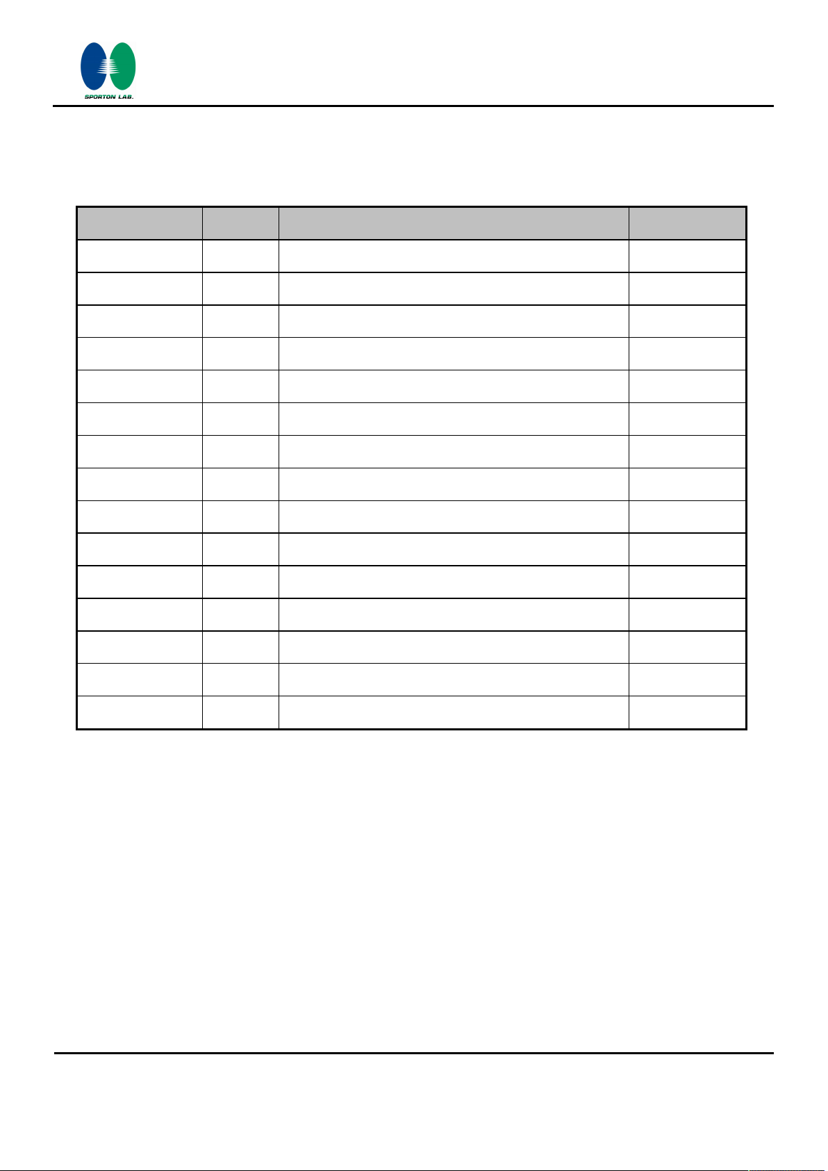
TABLE OF CONTENTS
REVISION HISTORY .......................................................................................................................................... 3
SUMMARY OF TEST RESULT ......................................................................................................................... 4
1 GENERAL DESCRIPTION .......................................................................................................................... 5
1.1 Applicant ............................................................................................................................................ 5
1.2 Manufacturer ...................................................................................................................................... 5
1.3 Product Feature of Equipment Under Test ........................................................................................ 5
1.4 Product Specification of Equipment Under Test ................................................................................ 6
1.5 Specification of Accessory ................................................................................................................. 6
1.6 Modification of EUT ........................................................................................................................... 6
1.7 Testing Location ................................................................................................................................ 6
1.8 Applicable Standards ......................................................................................................................... 7
2 TEST CONFIGURATION OF EQUIPMENT UNDER TEST ........................................................................ 8
2.1 Carrier Frequency and Channel ........................................................................................................ 8
2.2 Pre-Scanned RF Power ..................................................................................................................... 9
2.3 Test Mode ........................................................................................................................................ 10
2.4 Connection Diagram of Test System ............................................................................................... 11
2.5 Support Unit used in test configuration and system ........................................................................ 13
2.6 EUT Operation Test Setup .............................................................................................................. 13
2.7 Measurement Results Explanation Example ................................................................................... 13
3 TEST RESULT ........................................................................................................................................... 14
3.1 6dB and 99% Bandwidth Measurement .......................................................................................... 14
3.2 Output Power Measurement ............................................................................................................ 16
3.3 Power Spectral Density Measurement ............................................................................................ 18
3.4 Conducted Band Edges and Spurious Emission Measurement ..................................................... 20
3.5 Radiated Band Edges and Spurious Emission Measurement ........................................................ 30
3.6 AC Conducted Emission Measurement........................................................................................... 34
3.7 Antenna Requirements .................................................................................................................... 38
4 LIST OF MEASURING EQUIPMENT ........................................................................................................ 39
5 UNCERTAINTY OF EVALUATION ........................................................................................................... 40
APPENDIX A. CONDUCTED TEST RESULTS
APPENDIX B. RADIATED SPURIOUS EMISSION
APPENDIX C. DUTY CYCLE PLOTS
APPENDIX D. SETUP PHOTOGRAPHS
SPORTON INTERNATIONAL (KUNSHAN) INC. Page Number : 2 of 40
TEL : 86-0512-5790-0158 Report Issued Date : Nov. 29, 2016
FAX : 86-0512-5790-0958 Report Version : Rev. 01
FCC ID : IHDT56VF2 Report Template No.: BU5-FR15CWL Version 1.3
FCC RF Test Report
Report No. : FR693004C
REVISION HISTORY
REPORT NO. VERSION
DESCRIPTION ISSUED DATE
FR693004C Rev. 01 Initial issue of report Nov. 29, 2016
SPORTON INTERNATIONAL (KUNSHAN) INC. Page Number : 3 of 40
TEL : 86-0512-5790-0158 Report Issued Date : Nov. 29, 2016
FAX : 86-0512-5790-0958 Report Version : Rev. 01
FCC ID : IHDT56VF2 Report Template No.: BU5-FR15CWL Version 1.3
FCC RF Test Report
Report No. : FR693004C
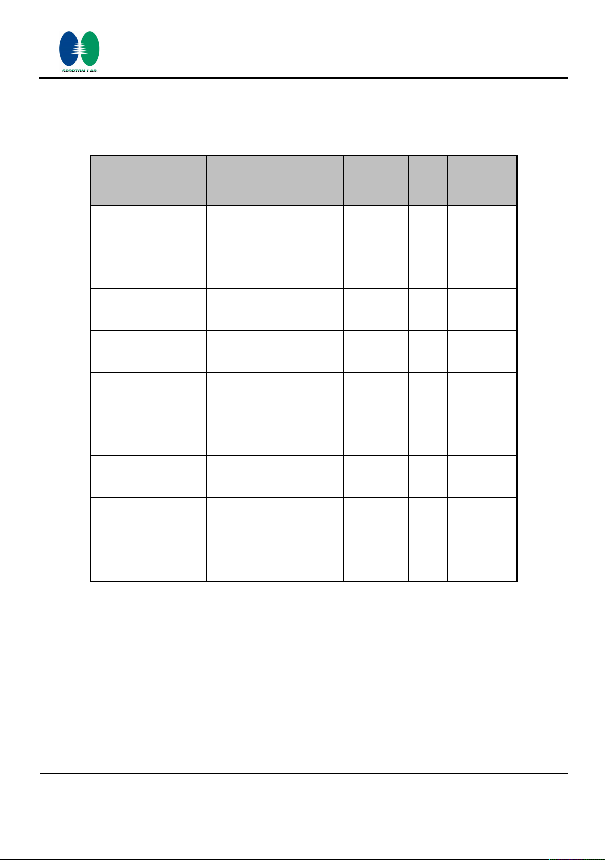
SUMMARY OF TEST RESULT
Report
FCC Rule Description Limit Result
Section
3.1 15.247(a)(2)
3.1 -
3.2 15.247(b)
3.3 15.247(e)
3.4 15.247(d)
3.5 15.247(d)
6dB Bandwidth
99% Bandwidth
Power Output Measurement
Power Spectral Density
Conducted Band Edges
Conducted Spurious Emission
Radiated Band Edges and
Radiated Spurious Emission
≥ 0.5MHz
-
≤ 30dBm
≤ 8dBm/3kHz
≤ 20dBc
15.209(a) &
15.247(d)
Pass
Pass
Pass
Pass
Pass
Pass
Pass
Remark
-
-
-
-
-
-
Under limit
3.04 dB at
2483.560 MHz
Under limit
3.6
3.7
15.207 AC Conducted Emission 15.207(a) Pass
15.203 &
15.247(b)
Antenna Requirement N/A Pass
10.08 dB at
0.521 MHz
-
SPORTON INTERNATIONAL (KUNSHAN) INC. Page Number : 4 of 40
TEL : 86-0512-5790-0158 Report Issued Date : Nov. 29, 2016
FAX : 86-0512-5790-0958 Report Version : Rev. 01
FCC ID : IHDT56VF2 Report Template No.: BU5-FR15CWL Version 1.3
FCC RF Test Report
1 General Description
1.1 Applicant
Motorola Mobility LLC
222 W, Merchandise Mart Plaza, Chicago IL 60654 USA
1.2 Manufacturer
Motorola Mobility LLC
222 W, Merchandise Mart Plaza, Chicago IL 60654 USA
1.3 Product Feature of Equipment Under Test
Product Feature
Equipment Mobile Cellular Phone
Brand Name Motorola
Model Name 9369, 9847
FCC ID IHDT56VF2
GSM/GPRS/EGPRS/WCDMA/HSPA/DC-HSDPA/
HSPA+(16QAM uplink is not supported)/LTE/
EUT supports Radios application
IMEI Code
HW Version
SW Version cedric-userdebug 7.0 NPP25.73 270 intcfg,test-keys
EUT Stage Production Unit
Remark:
1. The above EUT's information was declared by manufacturer. Please refer to the specifications or
user's manual for more detailed description.
2. There are two types of EUT sample 1 and sample 2, the differences between two samples are only
for SIM slot, sample 1(Model name: 9369) is dual SIM slot, sample 2(Model name: 9847) is single
SIM slot. According to the difference, the sample 1 to perform full test.
WLAN 2.4GHz 802.11b/g/n HT20/
WLAN 5GHz 802.11a/n HT20/HT40/
Bluetooth v3.0 + EDR/Bluetooth v4.0 LE/
Bluetooth v4.2 LE
Conducted: 351864080029279/351864080029287
Radiation: 351864080029311/351864080029329
Conduction: 351864080029238/351864080029246
DVT2(V5.0)
Report No. : FR693004C
SPORTON INTERNATIONAL (KUNSHAN) INC. Page Number : 5 of 40
TEL : 86-0512-5790-0158 Report Issued Date : Nov. 29, 2016
FAX : 86-0512-5790-0958 Report Version : Rev. 01
FCC ID : IHDT56VF2 Report Template No.: BU5-FR15CWL Version 1.3

FCC RF Test Report
1.4 Product Specification of Equipment Under Test
Standards-related Product Specification
Tx/Rx Channel Frequency Range 2412 MHz ~ 2462 MHz
Maximum (Peak) Output Power to
antenna
99% Occupied Bandwidth
Antenna Type / Gain PIFA Antenna with gain -1.55 dBi
Type of Modulation
802.11b : 20.22 dBm (0.1052 W)
802.11g : 20.82 dBm (0.1208 W)
802.11n HT20 : 19.51 dBm (0.0893 W)
802.11b : 13.74MHz
802.11g : 18.68MHz
802.11n HT20 : 19.48MHz
802.11b : DSSS (DBPSK / DQPSK / CCK)
802.11g/n : OFDM (BPSK / QPSK / 16QAM / 64QAM)
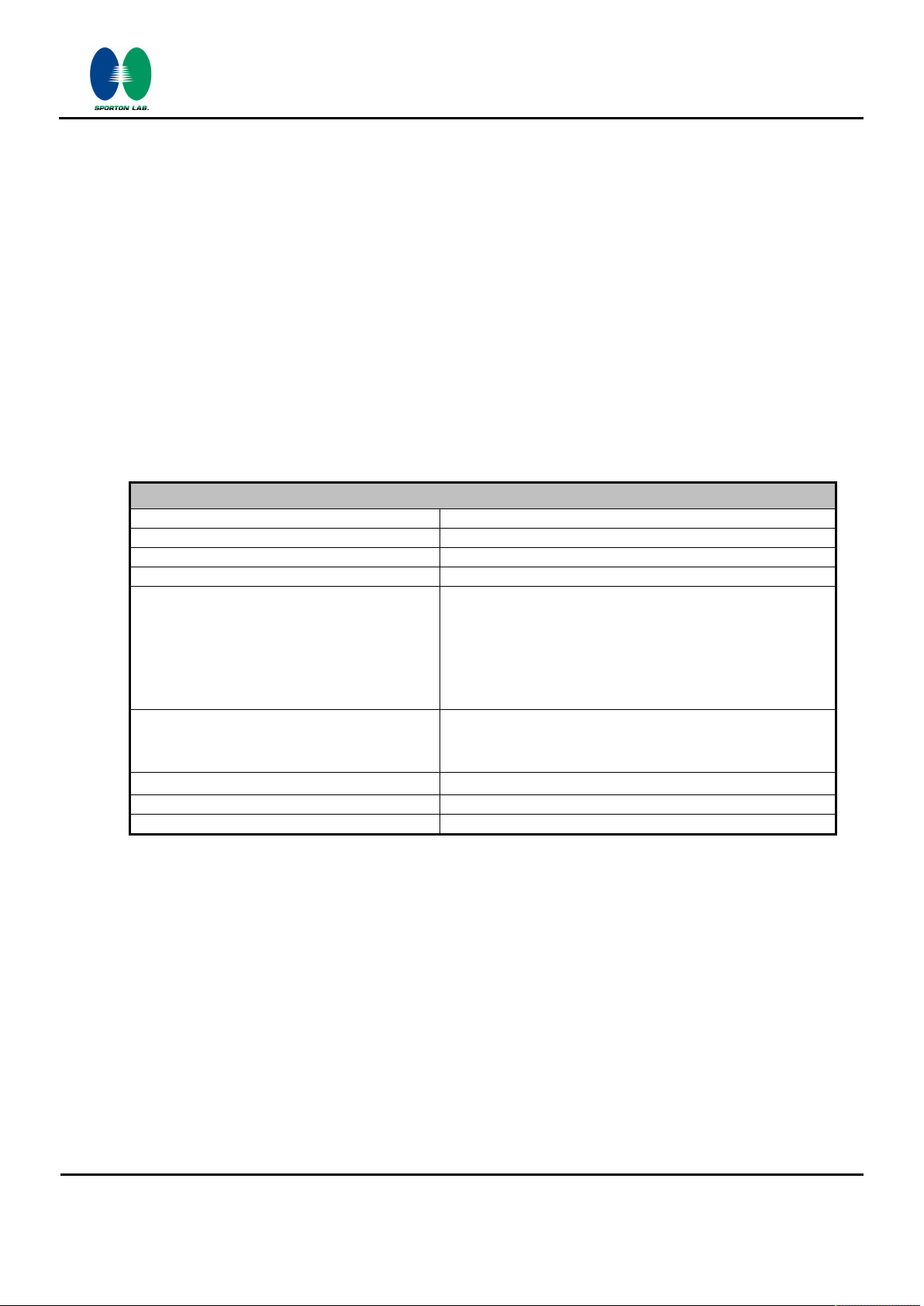
1.5 Specification of Accessory
Specification of Accessory
Report No. : FR693004C
AC Adapter
Battery
Earphone
USB Cable
Brand Name Motorola (Acbel)
Power Rating I/P: 100-240 Vac, 300mA, O/P: 5.2Vdc, 2000mA
Brand Name Motorola (ATL)
Power Rating
Brand Name Motorola Model Name SJYN1181B
Signal Line Type 1.2 meter, non-shielded cable, without ferrite core
Brand Name Motorola (Liqi) Model Name L25W-051000100AL
Signal Line Type 1.0 meter, non-shielded cable, without ferrite core
3.8Vdc, 2685/2800mAh
(Min/Typ)
1.6 Modification of EUT
No modifications are made to the EUT during all test items.
1.7 Testing Location
Test Site
Test Site Location
SPORTON INTERNATIONAL (KUNSHAN) INC.
No. 3-2, PingXiang Road, Kunshan, Jiangsu Province, P. R. China
TEL: +86-0512-5790-0158
Model Name
Model Name
Type
C-P35
GK40
Li-ion
FAX: +86-0512-5790-0958
Test Site No.
TH01-KS 03CH03-KS CO01-KS 306251
Note: The test site complies with ANSI C63.4 2014 requirement.
SPORTON INTERNATIONAL (KUNSHAN) INC. Page Number : 6 of 40
TEL : 86-0512-5790-0158 Report Issued Date : Nov. 29, 2016
FAX : 86-0512-5790-0958 Report Version : Rev. 01
FCC ID : IHDT56VF2 Report Template No.: BU5-FR15CWL Version 1.3
Sporton Site No. FCC Registration No.

FCC RF Test Report
1.8 Applicable Standards
According to the specifications of the manufacturer, the EUT must comply with the requirements of the
following standards:
FCC Part 15 Subpart C §15.247
FCC KDB Publication No. 558074 D01 DTS Meas. Guidance v03r05
ANSI C63.10-2013
Remark:
1. All test items were verified and recorded according to the standards and without any deviation
during the test.
2. This EUT has also been tested and complied with the requirements of FCC Part 15, Subpart B,
recorded in a separate test report.
Report No. : FR693004C
SPORTON INTERNATIONAL (KUNSHAN) INC. Page Number : 7 of 40
TEL : 86-0512-5790-0158 Report Issued Date : Nov. 29, 2016
FAX : 86-0512-5790-0958 Report Version : Rev. 01
FCC ID : IHDT56VF2 Report Template No.: BU5-FR15CWL Version 1.3
FCC RF Test Report
2 Test Configuration of Equipment Under Test
The EUT has been associated with peripherals and configuration operated in a manner tended to
maximize its emission characteristics in a typical application. Frequency range investigated: conducted
emission (150 kHz to 30 MHz) and radiated emission (9 kHz to the 10th harmonic of the highest
fundamental frequency or to 40 GHz, whichever is lower). For radiated measurement, pre-scanned in
three orthogonal panels, X, Y, Z. The worst cases were recorded in this report.
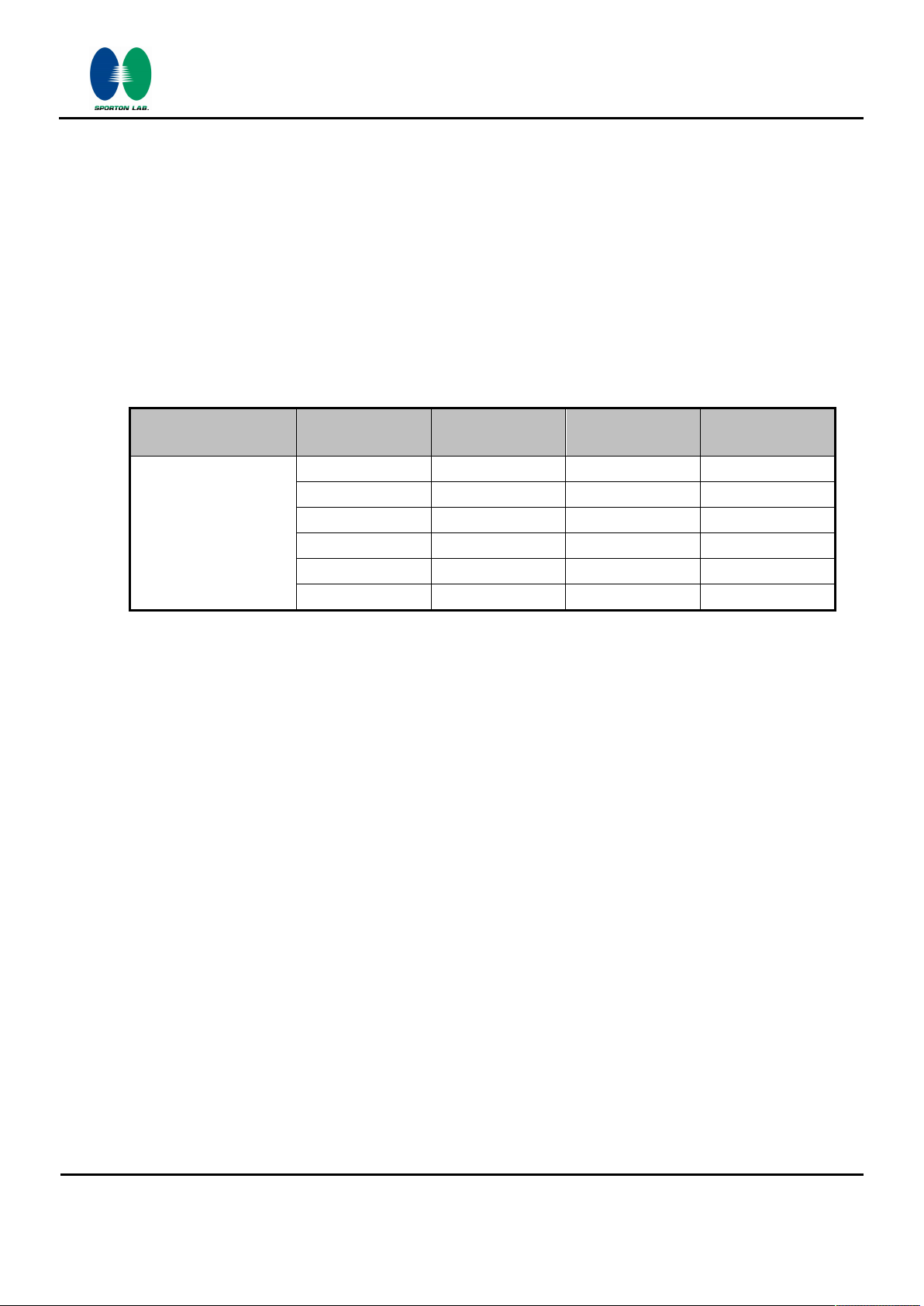
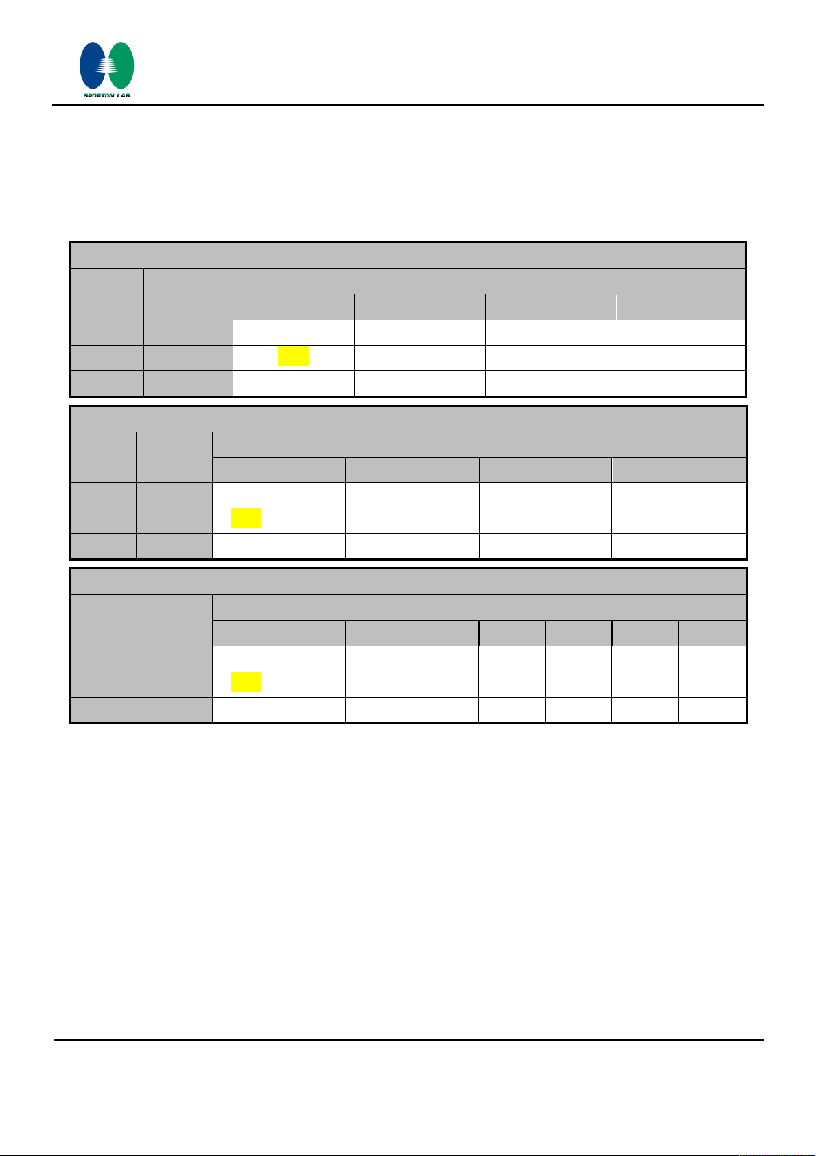
2.1 Carrier Frequency and Channel
Report No. : FR693004C
Frequency Band Channel
1 2412 7 2442
2 2417 8 2447
2400-2483.5 MHz
3 2422 9 2452
4 2427 10 2457
5 2432 11 2462
6 2437 - -
Freq.
(MHz)
Channel
Freq.
(MHz)
SPORTON INTERNATIONAL (KUNSHAN) INC. Page Number : 8 of 40
TEL : 86-0512-5790-0158 Report Issued Date : Nov. 29, 2016
FAX : 86-0512-5790-0958 Report Version : Rev. 01
FCC ID : IHDT56VF2 Report Template No.: BU5-FR15CWL Version 1.3
FCC RF Test Report
2.2 Pre-Scanned RF Power
Preliminary tests were performed in different data rate and data rate associated with the highest power
were chosen for full test shown in the following tables.
Report No. : FR693004C
Channel
CH 01 2412 MHz
CH 06 2437 MHz 20.22
CH 11 2462 MHz
Channel
CH 01 2412 MHz
CH 06 2437 MHz
CH 11 2462 MHz
Channel
Freq.
Freq.
Freq.
(MHz)
1M bps 2M bps 5.5M bps 11M bps
19.02 19.00 18.95 18.99
19.66 19.59 19.65 19.57
(MHz)
6M bps 9M bps 12M bps 18M bps 24M bps 36M bps 48M bps 54M bps
19.92
20.82
20.43
(MHz)
MCS0 MCS1 MCS2 MCS3 MCS4 MCS5 MCS6 MCS7
802.11b mode
802.11g mode
19.90
20.78
20.38
Peak Power (dBm)
20.16 20.18 20.20
Peak Power (dBm)
19.82
20.80
20.36
802.11n HT20 mode
Data Rate (MHz)
Data Rate (MHz)
19.86
20.77
20.35
19.91
20.67
20.42
Peak Power (dBm)
Data Rate (MHz)
19.85
20.75
20.40
19.89
20.76
20.37
19.88
20.69
20.32
CH 01 2412 MHz
CH 06 2437 MHz
CH 11 2462 MHz
19.42
19.51
18.33
19.39
19.45
18.31
19.38
19.38
18.24
19.35
19.37
18.26
19.40
19.39
18.18
19.34
19.46
18.20
19.41
19.50
18.27
SPORTON INTERNATIONAL (KUNSHAN) INC. Page Number : 9 of 40
TEL : 86-0512-5790-0158 Report Issued Date : Nov. 29, 2016
FAX : 86-0512-5790-0958 Report Version : Rev. 01
FCC ID : IHDT56VF2 Report Template No.: BU5-FR15CWL Version 1.3
19.31
19.48
18.30
FCC RF Test Report
2.3 Test Mode
Final test mode of conducted test items and radiated spurious emissions are considering the
modulation and worse data rates from the power table described in section 2.2.
Modulation Data Rate
802.11b 1 Mbps
802.11g 6 Mbps
802.11n HT20 MCS0
Test Cases
Report No. : FR693004C
AC Conducted
Emission
Mode 1 : GSM850 Idle + Bluetooth Link + WLAN (2.4G) Link + USB Cable (Charging from Adapter) +
Earphone
SPORTON INTERNATIONAL (KUNSHAN) INC. Page Number : 10 of 40
TEL : 86-0512-5790-0158 Report Issued Date : Nov. 29, 2016
FAX : 86-0512-5790-0958 Report Version : Rev. 01
FCC ID : IHDT56VF2 Report Template No.: BU5-FR15CWL Version 1.3
FCC RF Test Report
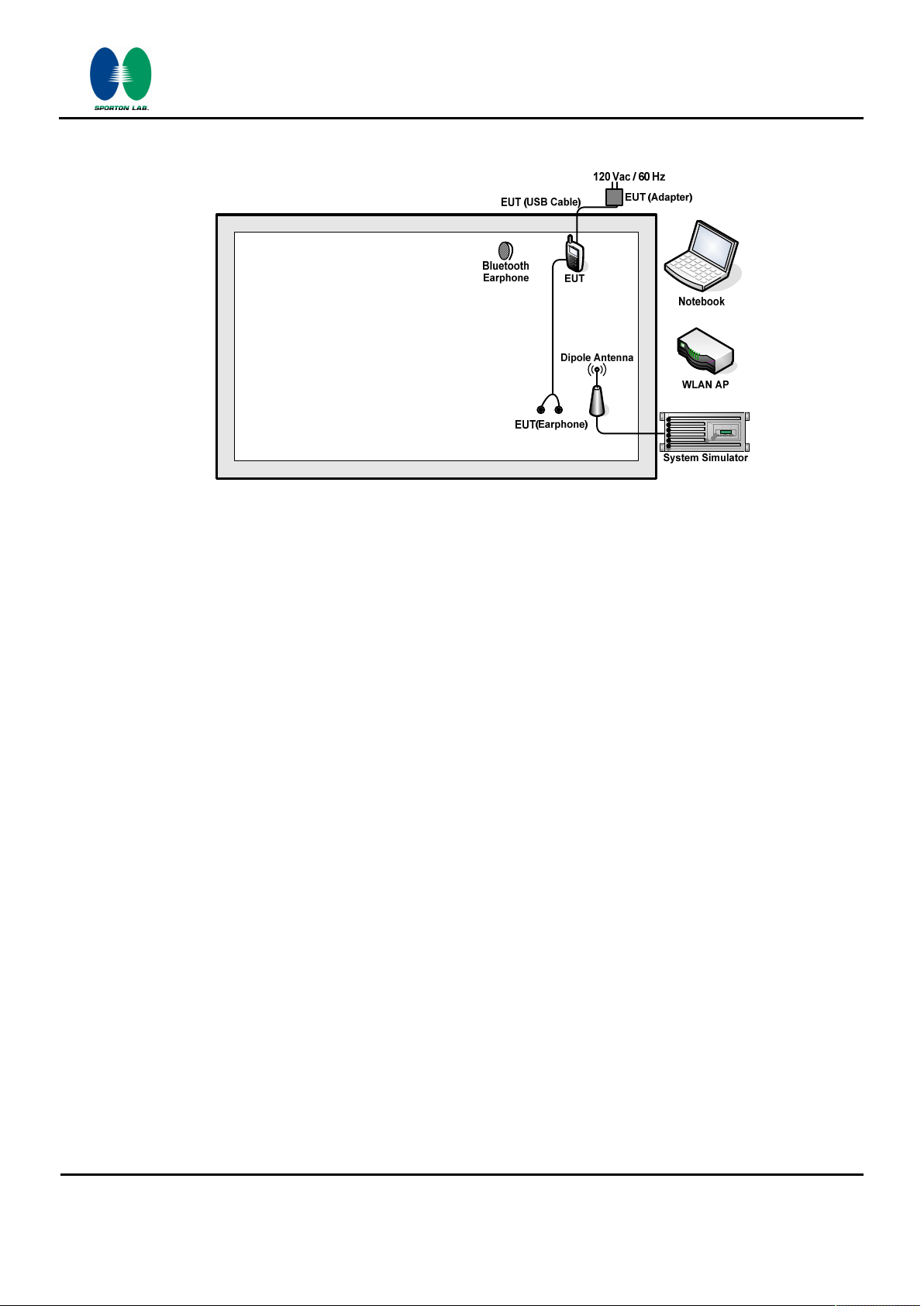
2.4 Connection Diagram of Test System
<WLAN b/g Tx Mode>
Report No. : FR693004C
<WLAN 11n(HT20) Tx Mode>
SPORTON INTERNATIONAL (KUNSHAN) INC. Page Number : 11 of 40
TEL : 86-0512-5790-0158 Report Issued Date : Nov. 29, 2016
FAX : 86-0512-5790-0958 Report Version : Rev. 01
FCC ID : IHDT56VF2 Report Template No.: BU5-FR15CWL Version 1.3
FCC RF Test Report
Report No. : FR693004C
<AC Conducted Emission Mode>
SPORTON INTERNATIONAL (KUNSHAN) INC. Page Number : 12 of 40
TEL : 86-0512-5790-0158 Report Issued Date : Nov. 29, 2016
FAX : 86-0512-5790-0958 Report Version : Rev. 01
FCC ID : IHDT56VF2 Report Template No.: BU5-FR15CWL Version 1.3
FCC RF Test Report
2.5 Support Unit used in test configuration and system
Item Equipment Trade Name Model Name FCC ID Data Cable Power Cord
1. System Simulator Anritsu MT8820C N/A N/A Unshielded, 1.8 m
Report No. : FR693004C
2. WLAN AP Linksys WRT600N Q87-WRT600NV11 N/A
Notebook Lenovo G480 FCC DoC N/A
3.
Bluetooth
4.
Earphone
Lenovo LBH308 N/A
N/A N/A
Unshielded, 1.8 m
Shielded cable
DC O/P 1.8 m
Unshielded AC
I/P cable1.2 m
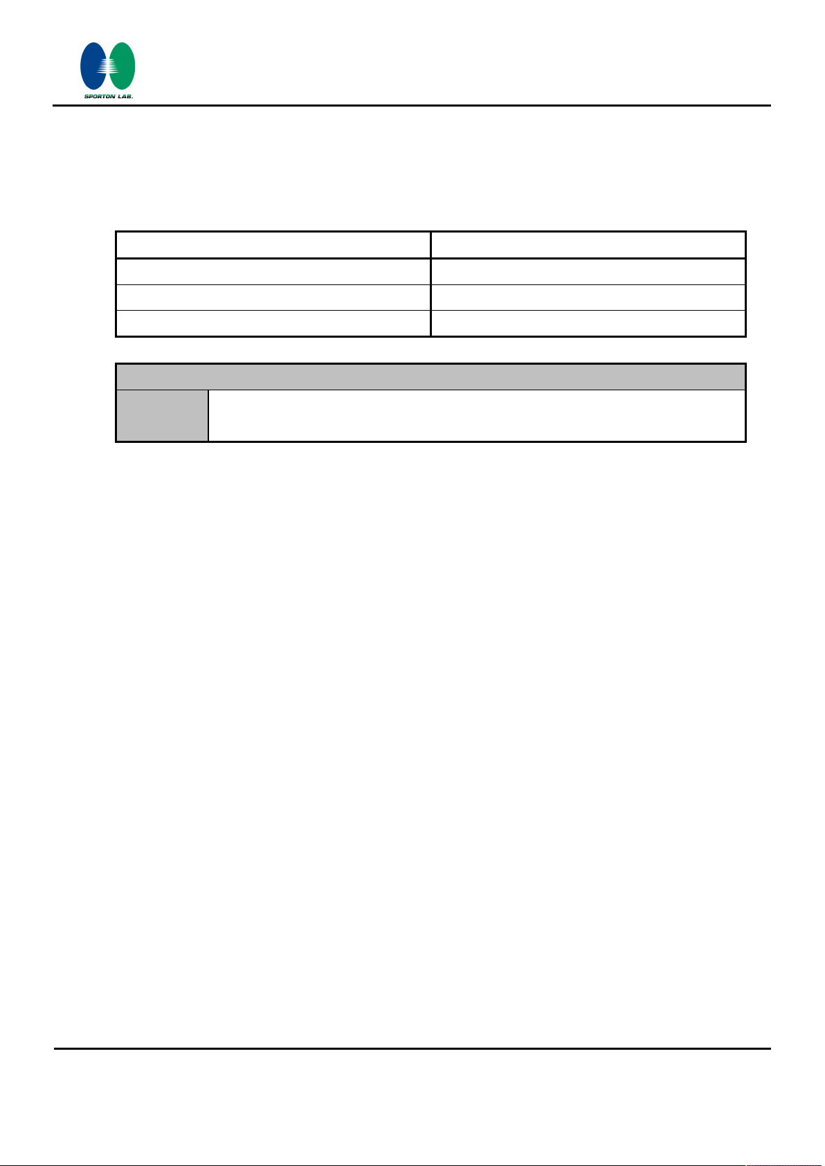
2.6 EUT Operation Test Setup
For WLAN function, the engineering test program was provided and enabled to make EUT continuous
transmit/receive.
For AC power line conducted emissions, the EUT was set to connect with the Notebook under large
package sizes transmission.
2.7 Measurement Results Explanation Example
For all conducted test items:
The offset level is set in the spectrum analyzer to compensate the RF cable loss between EUT
conducted output port and spectrum analyzer. With the offset compensation, the spectrum analyzer
reading level is exactly the EUT RF output level.
Example :
The spectrum analyzer offset is derived from RF cable loss.
Offset = RF cable loss.
Following shows an offset computation example with cable loss 5.8 dB.
Offset(dB) = RF cable loss(dB).
= 5.8 (dB)
SPORTON INTERNATIONAL (KUNSHAN) INC. Page Number : 13 of 40
TEL : 86-0512-5790-0158 Report Issued Date : Nov. 29, 2016
FAX : 86-0512-5790-0958 Report Version : Rev. 01
FCC ID : IHDT56VF2 Report Template No.: BU5-FR15CWL Version 1.3
FCC RF Test Report
3 Test Result
3.1 6dB and 99% Bandwidth Measurement
3.1.1 Limit of 6dB and 99% Bandwidth
The minimum 6 dB bandwidth shall be at least 500 kHz.
3.1.2 Measuring Instruments
The measuring equipment is listed in the section 4 of this test report.
3.1.3 Test Procedures
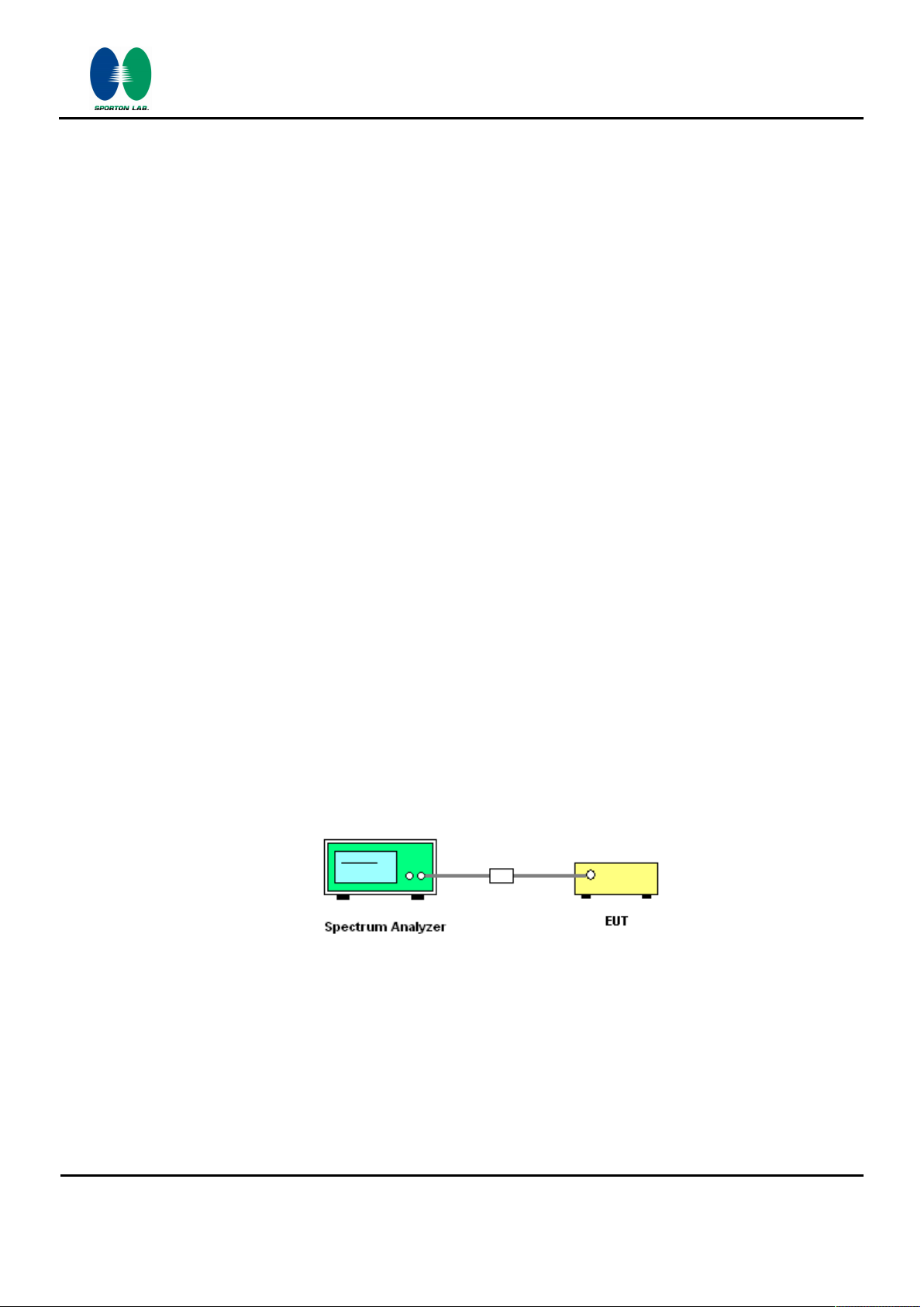
1. The testing follows FCC KDB Publication No. 558074 DTS D01 Meas. Guidance v03r05.
Report No. : FR693004C
2. The RF output of EUT was connected to the spectrum analyzer by RF cable and attenuator. The
path loss was compensated to the results for each measurement.
3. Set to the maximum power setting and enable the EUT transmit continuously.
4. Make the measurement with the spectrum analyzer's resolution bandwidth (RBW) = 100 kHz.
Set the Video bandwidth (VBW) = 300 kHz. In order to make an accurate measurement. The 6
dB bandwidth must be greater than 500 kHz.
5. For 99% Bandwidth Measurement, the spectrum analyzer's resolution bandwidth (RBW) =
1MHz and set the Video bandwidth (VBW) = 3MHz.
6. Measure and record the results in the test report.
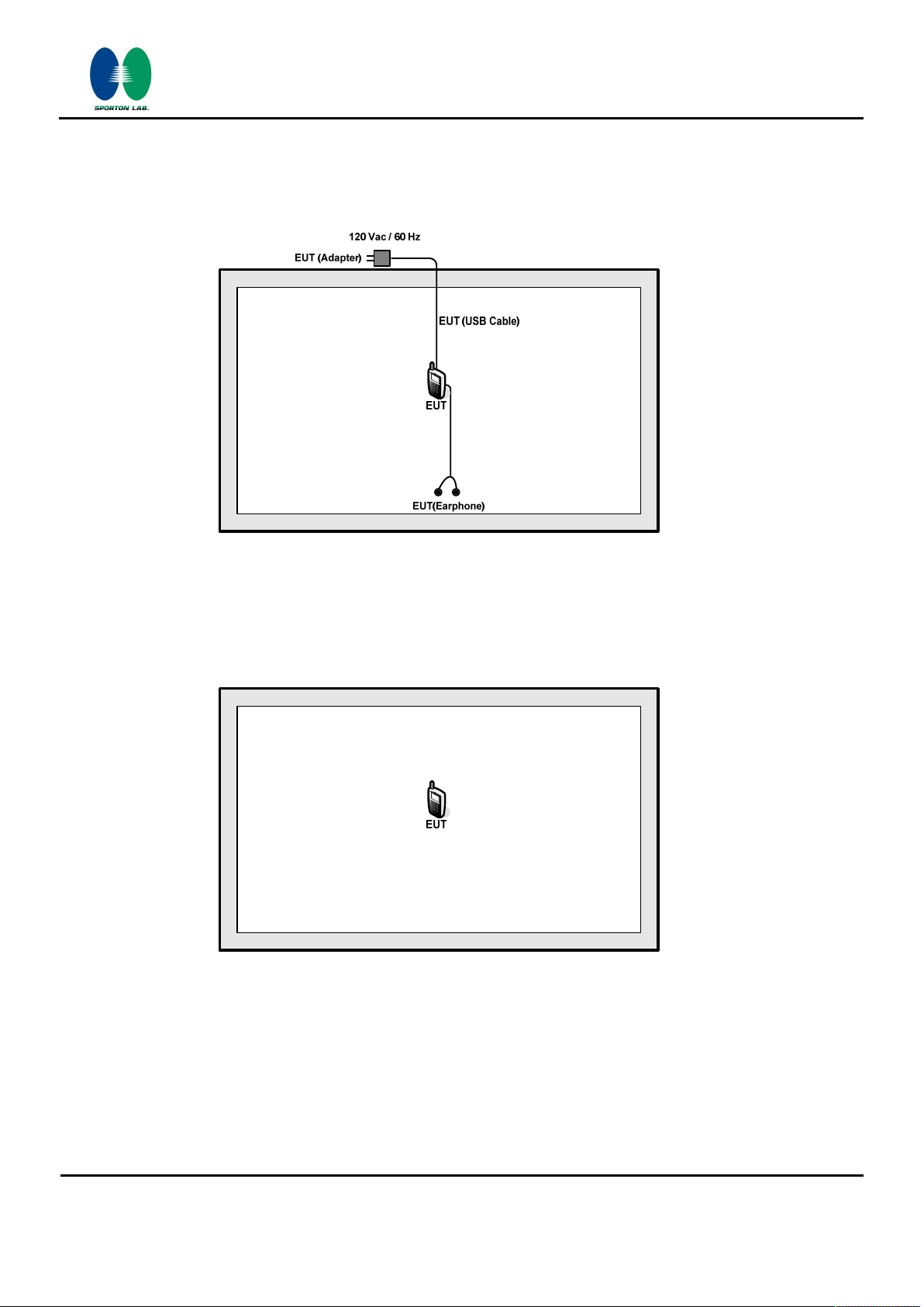
3.1.4 Test Setup
SPORTON INTERNATIONAL (KUNSHAN) INC. Page Number : 14 of 40
TEL : 86-0512-5790-0158 Report Issued Date : Nov. 29, 2016
FAX : 86-0512-5790-0958 Report Version : Rev. 01
FCC ID : IHDT56VF2 Report Template No.: BU5-FR15CWL Version 1.3
FCC RF Test Report
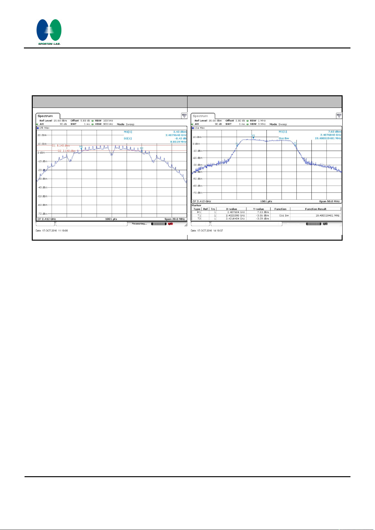
3.1.5 Test Result of 6dB and 99% Occupied Bandwidth
Please refer to Appendix A.
Minimum 6dB Bandwidth Maximum 99% Occupied Bandwidth
Report No. : FR693004C
Note : The occupied channel bandwidth is maintained within the band of operation for all of the modulations.
SPORTON INTERNATIONAL (KUNSHAN) INC. Page Number : 15 of 40
TEL : 86-0512-5790-0158 Report Issued Date : Nov. 29, 2016
FAX : 86-0512-5790-0958 Report Version : Rev. 01
FCC ID : IHDT56VF2 Report Template No.: BU5-FR15CWL Version 1.3
FCC RF Test Report
3.2 Output Power Measurement
3.2.1 Limit of Output Power
For systems using digital modulation in the 2400-2483.5MHz, the limit for peak output power is
30dBm. If transmitting antenna of directional gain greater than 6dBi are used the peak output power
from the intentional radiator shall be reduced below the above stated value by the amount in dB that
the directional gain of the antenna exceeds 6 dBi. In case of point-to-point operation, the limit has to
be reduced by 1dB for every 3dB that the directional gain of the antenna exceeds 6dBi.
3.2.2 Measuring Instruments
The measuring equipment is listed in the section 4 of this test report.
Report No. : FR693004C
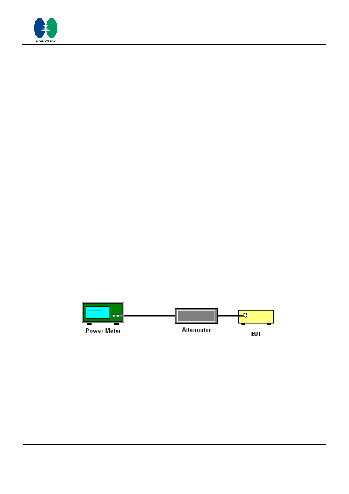
3.2.3 Test Procedures
1. The testing follows the Measurement Procedure of FCC KDB No. 558074 DTS D01 Meas.
Guidance v03r05 section 9.1.2 PKPM1 Peak power meter method.
2. The RF output of EUT was connected to the power meter by RF cable and attenuator. The path
loss was compensated to the results for each measurement.
3. Set to the maximum power setting and enable the EUT transmit continuously.
4. Measure the conducted output power and record the results in the test report.
3.2.4 Test Setup
SPORTON INTERNATIONAL (KUNSHAN) INC. Page Number : 16 of 40
TEL : 86-0512-5790-0158 Report Issued Date : Nov. 29, 2016
FAX : 86-0512-5790-0958 Report Version : Rev. 01
FCC ID : IHDT56VF2 Report Template No.: BU5-FR15CWL Version 1.3

FCC RF Test Report
3.2.5 Test Result of Peak Output Power
Please refer to Appendix A.
3.2.6 Test Result of Average output Power (Reporting Only)
Please refer to Appendix A.
Report No. : FR693004C
SPORTON INTERNATIONAL (KUNSHAN) INC. Page Number : 17 of 40
TEL : 86-0512-5790-0158 Report Issued Date : Nov. 29, 2016
FAX : 86-0512-5790-0958 Report Version : Rev. 01
FCC ID : IHDT56VF2 Report Template No.: BU5-FR15CWL Version 1.3

FCC RF Test Report
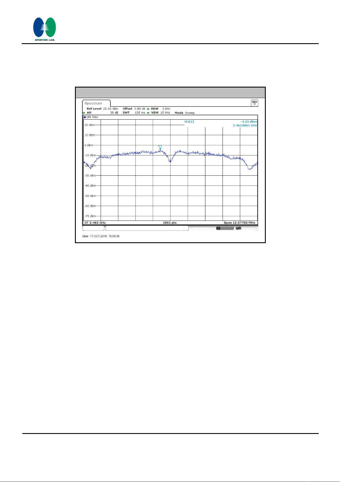
3.3 Power Spectral Density Measurement
3.3.1 Limit of Power Spectral Density
The peak power spectral density shall not be greater than 8dBm in any 3kHz band at any time interval
of continuous transmission.
3.3.2 Measuring Instruments
The measuring equipment is listed in the section 4 of this test report.
3.3.3 Test Procedures
1. The testing follows Measurement Procedure 10.2 Method PKPSD of FCC KDB Publication No.
558074 D01 DTS Meas. Guidance v03r05
Report No. : FR693004C
2. The RF output of EUT was connected to the spectrum analyzer by RF cable and attenuator. The
path loss was compensated to the results for each measurement.
3. Set to the maximum power setting and enable the EUT transmit continuously.
4. Make the measurement with the spectrum analyzer's resolution bandwidth (RBW) = 3 kHz.
Video bandwidth VBW = 10 kHz In order to make an accurate measurement, set the span to 1.5
times DTS Channel Bandwidth. (6dB BW)
5. Detector = peak, Sweep time = auto couple, Trace mode = max hold, Allow trace to fully
stabilize. Use the peak marker function to determine the maximum power level.
6. Measure and record the results in the test report.
3.3.4 Test Setup
SPORTON INTERNATIONAL (KUNSHAN) INC. Page Number : 18 of 40
TEL : 86-0512-5790-0158 Report Issued Date : Nov. 29, 2016
FAX : 86-0512-5790-0958 Report Version : Rev. 01
FCC ID : IHDT56VF2 Report Template No.: BU5-FR15CWL Version 1.3
FCC RF Test Report
3.3.5 Test Result of Power Spectral Density
Please refer to Appendix A.
Worst Case Power Density (dBm/3kHz)
Report No. : FR693004C
SPORTON INTERNATIONAL (KUNSHAN) INC. Page Number : 19 of 40
TEL : 86-0512-5790-0158 Report Issued Date : Nov. 29, 2016
FAX : 86-0512-5790-0958 Report Version : Rev. 01
FCC ID : IHDT56VF2 Report Template No.: BU5-FR15CWL Version 1.3

FCC RF Test Report
Report No. : FR693004C
3.4 Conducted Band Edges and Spurious Emission Measurement
3.4.1 Limit of Conducted Band Edges and Spurious Emission Measurement
In any 100 kHz bandwidth outside of the authorized frequency band, the emissions which fall in the
non-restricted bands shall be attenuated at least 20 dB / 30dB relative to the maximum PSD level in
100 kHz by RF conducted measurement and radiated emissions which fall in the restricted bands, as
defined in Section 15.205(a), must also comply with the radiated emission limits specified in Section
15.209(a).
3.4.2 Measuring Instruments
The measuring equipment is listed in the section 4 of this test report.
3.4.3 Test Procedures
1. The testing follows FCC KDB Publication No. 558074 D01 DTS Meas. Guidance v03r05.
2. The RF output of EUT was connected to the spectrum analyzer by RF cable and attenuator. The
path loss was compensated to the results for each measurement.
3. Set to the maximum power setting and enable the EUT transmit continuously.
4. Set RBW = 100 kHz, VBW=300 kHz, Peak Detector. Unwanted Emissions measured in any 100
kHz bandwidth outside of the authorized frequency band shall be attenuated by at least 20 dB
relative to the maximum in-band peak PSD level in 100 kHz when maximum peak conducted
output power procedure is used. If the transmitter complies with the conducted power limits
based on the use of RMS averaging over a time interval, the attenuation required under this
paragraph shall be 30 dB instead of 20 dB per 15.247(d).
5. Measure and record the results in the test report.
6. The RF fundamental frequency should be excluded against the limit line in the operating
frequency band.
3.4.4 Test Setup
SPORTON INTERNATIONAL (KUNSHAN) INC. Page Number : 20 of 40
TEL : 86-0512-5790-0158 Report Issued Date : Nov. 29, 2016
FAX : 86-0512-5790-0958 Report Version : Rev. 01
FCC ID : IHDT56VF2 Report Template No.: BU5-FR15CWL Version 1.3

FCC RF Test Report
Report No. : FR693004C
3.4.5 Test Result of Conducted Band Edges and Spurious Emission
Test Mode : 802.11b Temperature : 24~25℃
Test Band : 2.4GHz Low Relative Humidity : 54~55%
Test Channel : 01 Test Engineer : Ivan Zhang
WLAN 802.11b Channel 01
100kHz PSD reference Level Low Channel Plot
Spurious Emission 30MHz~3GHz Spurious Emission 2GHz~25GHz
SPORTON INTERNATIONAL (KUNSHAN) INC. Page Number : 21 of 40
TEL : 86-0512-5790-0158 Report Issued Date : Nov. 29, 2016
FAX : 86-0512-5790-0958 Report Version : Rev. 01
FCC ID : IHDT56VF2 Report Template No.: BU5-FR15CWL Version 1.3

FCC RF Test Report
Report No. : FR693004C
Test Mode : 802.11b Temperature : 24~25℃
Test Band : 2.4GHz Mid Relative Humidity : 54~55%
Test Channel : 06 Test Engineer : Ivan Zhang
WLAN 802.11b Channel 06
100kHz PSD reference Level
Spurious Emission 30MHz~3GHz Spurious Emission 2GHz~25GHz
SPORTON INTERNATIONAL (KUNSHAN) INC. Page Number : 22 of 40
TEL : 86-0512-5790-0158 Report Issued Date : Nov. 29, 2016
FAX : 86-0512-5790-0958 Report Version : Rev. 01
FCC ID : IHDT56VF2 Report Template No.: BU5-FR15CWL Version 1.3

FCC RF Test Report
Report No. : FR693004C
Test Mode : 802.11b Temperature : 24~25℃
Test Band : 2.4GHz High Relative Humidity : 54~55%
Test Channel : 11 Test Engineer : Ivan Zhang
WLAN 802.11b Channel 11
100kHz PSD reference Level High Channel Plot
Spurious Emission 30MHz~3GHz Spurious Emission 2GHz~25GHz
SPORTON INTERNATIONAL (KUNSHAN) INC. Page Number : 23 of 40
TEL : 86-0512-5790-0158 Report Issued Date : Nov. 29, 2016
FAX : 86-0512-5790-0958 Report Version : Rev. 01
FCC ID : IHDT56VF2 Report Template No.: BU5-FR15CWL Version 1.3

FCC RF Test Report
Report No. : FR693004C
Test Mode : 802.11g Temperature : 24~25℃
Test Band : 2.4GHz Low Relative Humidity : 54~55%
Test Channel : 01 Test Engineer : Ivan Zhang
WLAN 802.11g Channel 01
100kHz PSD reference Level Low Channel Plot
Spurious Emission 30MHz~3GHz Spurious Emission 2GHz~25GHz
SPORTON INTERNATIONAL (KUNSHAN) INC. Page Number : 24 of 40
TEL : 86-0512-5790-0158 Report Issued Date : Nov. 29, 2016
FAX : 86-0512-5790-0958 Report Version : Rev. 01
FCC ID : IHDT56VF2 Report Template No.: BU5-FR15CWL Version 1.3

FCC RF Test Report
Report No. : FR693004C
Test Mode : 802.11g Temperature : 24~25℃
Test Band : 2.4GHz Mid Relative Humidity : 54~55%
Test Channel : 06 Test Engineer : Ivan Zhang
WLAN 802.11g Channel 06
100kHz PSD reference Level
Spurious Emission 30MHz~3GHz Spurious Emission 2GHz~25GHz
SPORTON INTERNATIONAL (KUNSHAN) INC. Page Number : 25 of 40
TEL : 86-0512-5790-0158 Report Issued Date : Nov. 29, 2016
FAX : 86-0512-5790-0958 Report Version : Rev. 01
FCC ID : IHDT56VF2 Report Template No.: BU5-FR15CWL Version 1.3

FCC RF Test Report
Report No. : FR693004C
Test Mode : 802.11g Temperature : 24~25℃
Test Band : 2.4GHz High Relative Humidity : 54~55%
Test Channel : 11 Test Engineer : Ivan Zhang
WLAN 802.11g Channel 11
100kHz PSD reference Level High Channel Plot
Spurious Emission 30MHz~3GHz Spurious Emission 2GHz~25GHz
SPORTON INTERNATIONAL (KUNSHAN) INC. Page Number : 26 of 40
TEL : 86-0512-5790-0158 Report Issued Date : Nov. 29, 2016
FAX : 86-0512-5790-0958 Report Version : Rev. 01
FCC ID : IHDT56VF2 Report Template No.: BU5-FR15CWL Version 1.3

FCC RF Test Report
Report No. : FR693004C
Test Mode : 802.11n HT20 Temperature : 24~25℃
Test Band : 2.4GHz Low Relative Humidity : 54~55%
Test Channel : 01 Test Engineer : Ivan Zhang
WLAN 802.11n HT20 Channel 01
100kHz PSD reference Level Low Channel Plot
Spurious Emission 30MHz~3GHz Spurious Emission 2GHz~25GHz
SPORTON INTERNATIONAL (KUNSHAN) INC. Page Number : 27 of 40
TEL : 86-0512-5790-0158 Report Issued Date : Nov. 29, 2016
FAX : 86-0512-5790-0958 Report Version : Rev. 01
FCC ID : IHDT56VF2 Report Template No.: BU5-FR15CWL Version 1.3

FCC RF Test Report
Report No. : FR693004C
Test Mode : 802.11n HT20 Temperature : 24~25℃
Test Band : 2.4GHz Mid Relative Humidity : 54~55%
Test Channel : 06 Test Engineer : Ivan Zhang
WLAN 802.11n HT20 Channel 06
100kHz PSD reference Level
Spurious Emission 30MHz~3GHz Spurious Emission 2GHz~25GHz
SPORTON INTERNATIONAL (KUNSHAN) INC. Page Number : 28 of 40
TEL : 86-0512-5790-0158 Report Issued Date : Nov. 29, 2016
FAX : 86-0512-5790-0958 Report Version : Rev. 01
FCC ID : IHDT56VF2 Report Template No.: BU5-FR15CWL Version 1.3

FCC RF Test Report
Report No. : FR693004C
Test Mode : 802.11n HT20 Temperature : 24~25℃
Test Band : 2.4GHz High Relative Humidity : 54~55%
Test Channel : 11 Test Engineer : Ivan Zhang
WLAN 802.11n HT20 Channel 11
100kHz PSD reference Level High Channel Plot
Spurious Emission 30MHz~3GHz Spurious Emission 2GHz~25GHz
SPORTON INTERNATIONAL (KUNSHAN) INC. Page Number : 29 of 40
TEL : 86-0512-5790-0158 Report Issued Date : Nov. 29, 2016
FAX : 86-0512-5790-0958 Report Version : Rev. 01
FCC ID : IHDT56VF2 Report Template No.: BU5-FR15CWL Version 1.3

FCC RF Test Report
Report No. : FR693004C
3.5 Radiated Band Edges and Spurious Emission Measurement
3.5.1 Limit of Radiated band edge and Spurious Emission Measurement
In any 100 kHz bandwidth outside the intentional radiator frequency band, all harmonics/spurious
must be at least 20 dB below the highest emission level within the authorized band. If the output
power of this device was measured by spectrum analyzer, the attenuation under this paragraph shall
be 30 dB instead of 20 dB. In addition, radiated emissions which fall in the restricted bands must also
comply with the FCC section 15.209 limits as below.
Frequency
(MHz)
0.009 – 0.490 2400/F(kHz) 300
0.490 – 1.705 24000/F(kHz) 30
1.705 – 30.0 30 30
30 – 88 100 3
88 – 216 150 3
216 - 960 200 3
Above 960 500 3
3.5.2 Measuring Instruments
The measuring equipment is listed in the section 4 of this test report.
Field Strength
(microvolts/meter)
Measurement Distance
(meters)
SPORTON INTERNATIONAL (KUNSHAN) INC. Page Number : 30 of 40
TEL : 86-0512-5790-0158 Report Issued Date : Nov. 29, 2016
FAX : 86-0512-5790-0958 Report Version : Rev. 01
FCC ID : IHDT56VF2 Report Template No.: BU5-FR15CWL Version 1.3

FCC RF Test Report
3.5.3 Test Procedures
1. The testing follows FCC KDB Publication No. 558074 D01 DTS Meas. Guidance v03r05.
2. The EUT was arranged to its worst case and then tune the antenna tower (from 1 m to 4 m) and
turntable (from 0 degree to 360 degrees) to find the maximum reading. A pre-amp and a high
pass filter are used for the test in order to get better signal level.
3. The EUT was placed on a turntable with 0.8 meter for frequency below 1GHz and 1.5 meter for
frequency above 1GHz respectively above ground.
4. The EUT was set 3 meters from the interference receiving antenna, which was mounted on the
top of a variable height antenna tower.
5. Corrected Reading: Antenna Factor + Cable Loss + Read Level - Preamp Factor = Level
6. For measurement below 1GHz, If the emission level of the EUT measured by the peak detector
is 3 dB lower than the applicable limit, the peak emission level will be reported. Otherwise, the
emission measurement will be repeated using the quasi-peak detector and reported.
Report No. : FR693004C
7. Use the following spectrum analyzer settings:
(1) Span shall wide enough to fully capture the emission being measured;
(2) Set RBW=100 kHz for f < 1 GHz; VBW RBW; Sweep = auto; Detector function = peak;
Trace = max hold;
(3) Set RBW = 1 MHz, VBW= 3MHz for f 1 GHz for peak measurement.
For average measurement:
• VBW = 10 Hz, when duty cycle is no less than 98 percent.
• VBW ≥ 1/T, when duty cycle is less than 98 percent where T is the minimum
transmission duration over which the transmitter is on and is transmitting at its maximum
power control level for the tested mode of operation.
SPORTON INTERNATIONAL (KUNSHAN) INC. Page Number : 31 of 40
TEL : 86-0512-5790-0158 Report Issued Date : Nov. 29, 2016
FAX : 86-0512-5790-0958 Report Version : Rev. 01
FCC ID : IHDT56VF2 Report Template No.: BU5-FR15CWL Version 1.3

FCC RF Test Report
3.5.4 Test Setup
For radiated emissions below 30MHz
Report No. : FR693004C
For radiated emissions from 30MHz to 1GHz
SPORTON INTERNATIONAL (KUNSHAN) INC. Page Number : 32 of 40
TEL : 86-0512-5790-0158 Report Issued Date : Nov. 29, 2016
FAX : 86-0512-5790-0958 Report Version : Rev. 01
FCC ID : IHDT56VF2 Report Template No.: BU5-FR15CWL Version 1.3

FCC RF Test Report
Report No. : FR693004C
For radiated emissions above 1GHz
3.5.5 Test Results of Radiated Spurious Emissions (9kHz ~ 30MHz)
The low frequency, which started from 9 kHz to 30MHz, was pre-scanned and the result which was
20dB lower than the limit line per 15.31(o) was not reported.
3.5.6 Test Result of Radiated Spurious at Band Edges
Please refer to Appendix B.
3.5.7 Duty Cycle
Please refer to Appendix C.
3.5.8 Test Result of Radiated Spurious Emission (30MHz ~ 10th Harmonic)
Please refer to Appendix B.
SPORTON INTERNATIONAL (KUNSHAN) INC. Page Number : 33 of 40
TEL : 86-0512-5790-0158 Report Issued Date : Nov. 29, 2016
FAX : 86-0512-5790-0958 Report Version : Rev. 01
FCC ID : IHDT56VF2 Report Template No.: BU5-FR15CWL Version 1.3

FCC RF Test Report
3.6 AC Conducted Emission Measurement
3.6.1 Limit of AC Conducted Emission
For equipment that is designed to be connected to the public utility (AC) power line, the radio
frequency voltage that is conducted back onto the AC power line on any frequency or frequencies
within the band 150 kHz to 30 MHz shall not exceed the limits in the following table.
Report No. : FR693004C
Frequency of Emission
(MHz)
0.15-0.5 66 to 56* 56 to 46*
0.5-5 56 46
5-30 60 50
*Decreases with the logarithm of the frequency.
3.6.2 Measuring Instruments
The measuring equipment is listed in the section 4 of this test report.
3.6.3 Test Procedures
1. The EUT was placed 0.4 meter from the conducting wall of the shielding room, and it was kept at
least 80 centimeters from any other grounded conducting surface.
2. Connect EUT to the power mains through a line impedance stabilization network (LISN).
3. All the support units are connecting to the other LISN.
Conducted Limit (dBμV)
Quasi-Peak Average
4. The LISN provides 50 ohm coupling impedance for the measuring instrument.
5. The FCC states that a 50 ohm, 50 microhenry LISN should be used.
6. Both sides of AC line were checked for maximum conducted interference.
7. The frequency range from 150 kHz to 30 MHz was searched.
8. Set the test-receiver system to Peak Detect Function and specified bandwidth (IF bandwidth =
9kHz) with Maximum Hold Mode.
SPORTON INTERNATIONAL (KUNSHAN) INC. Page Number : 34 of 40
TEL : 86-0512-5790-0158 Report Issued Date : Nov. 29, 2016
FAX : 86-0512-5790-0958 Report Version : Rev. 01
FCC ID : IHDT56VF2 Report Template No.: BU5-FR15CWL Version 1.3

FCC RF Test Report
3.6.4 Test Setup
Report No. : FR693004C
SPORTON INTERNATIONAL (KUNSHAN) INC. Page Number : 35 of 40
TEL : 86-0512-5790-0158 Report Issued Date : Nov. 29, 2016
FAX : 86-0512-5790-0958 Report Version : Rev. 01
FCC ID : IHDT56VF2 Report Template No.: BU5-FR15CWL Version 1.3

GSM850 Idle + Bluetooth Link + WLAN (2.4G) Link + USB Cable (Charging from
FCC RF Test Report
3.6.5 Test Result of AC Conducted Emission
Report No. : FR693004C
Test Mode :
Test Engineer :
Test Voltage :
Function Type :
Mode 1
Amos Zhang
120Vac / 60Hz
Adapter) + Earphone
Temperature :
Relative Humidity :
Phase :
22~24℃
43~47%
Line
SPORTON INTERNATIONAL (KUNSHAN) INC. Page Number : 36 of 40
TEL : 86-0512-5790-0158 Report Issued Date : Nov. 29, 2016
FAX : 86-0512-5790-0958 Report Version : Rev. 01
FCC ID : IHDT56VF2 Report Template No.: BU5-FR15CWL Version 1.3

Idle + Bluetooth Link + WLAN (2.4G) Link + USB Cable (Charging from
FCC RF Test Report
Report No. : FR693004C
Test Mode :
Test Engineer :
Test Voltage :
Function Type :
Mode 1
Amos Zhang
120Vac / 60Hz
GSM850
Adapter) + Earphone
Temperature :
Relative Humidity :
Phase :
22~24℃
43~47%
Neutral
SPORTON INTERNATIONAL (KUNSHAN) INC. Page Number : 37 of 40
TEL : 86-0512-5790-0158 Report Issued Date : Nov. 29, 2016
FAX : 86-0512-5790-0958 Report Version : Rev. 01
FCC ID : IHDT56VF2 Report Template No.: BU5-FR15CWL Version 1.3

FCC RF Test Report
3.7 Antenna Requirements
3.7.1 Standard Applicable
If directional gain of transmitting antennas is greater than 6dBi, the power shall be reduced by the
same level in dB comparing to gain minus 6dBi. The use of a permanently attached antenna or of an
antenna that uses a unique coupling to the intentional radiator shall be considered sufficient to
comply with the FCC rule.
3.7.2 Antenna Anti-Replacement Construction
An embedded-in antenna design is used.
3.7.3 Antenna Gain
Report No. : FR693004C
The antenna peak gain of EUT is less than 6 dBi. Therefore, it is not necessary to reduce maximum
peak output power limit.
SPORTON INTERNATIONAL (KUNSHAN) INC. Page Number : 38 of 40
TEL : 86-0512-5790-0158 Report Issued Date : Nov. 29, 2016
FAX : 86-0512-5790-0958 Report Version : Rev. 01
FCC ID : IHDT56VF2 Report Template No.: BU5-FR15CWL Version 1.3

FCC RF Test Report
4 List of Measuring Equipment
Report No. : FR693004C
Instrument Manufacturer Model No. Serial No. Characteristics
Spectrum
Analyzer
Pulse Power
Senor
Power Meter Anritsu ML2495A 1005002
EMI Test Receiver
EXA Spectrum
Analyzer
Loop Antenna R&S HFH2-Z2 100321 9kHz~30MHz Nov. 07, 2015
Bilog Antenna TeseQ CBL6112D 35406 25MHz~2GHz Apr. 16, 2016
Horn Antenna Schwarzbeck BBHA9120D
SHF-EHF Horn
Amplifier SONOMA 310N 187289 9kHz~1GHz Aug. 09, 2016
High Gain
Amplifier
Amplifier Agilent 8449B
AC Power Source Chroma 61601
Turn Table ChamPro EM 1000-T 060762-T 0~360 degree
Antenna Mast ChamPro EM 1000-A 060762-A 1 m~4 m NCR
EMI Receiver R&S ESCI7 100768 9kHz~7GHz; Apr. 29, 2016 Oct. 11, 2016 Apr. 28, 2017
AC LISN MessTec AN3016 060103 9kHz~30MHz Oct. 24, 2015 Oct. 11, 2016 Oct. 23, 2016
AC LISN
(for auxiliary
equipment)
AC Power Source
NCR: No Calibration Required
R&S FSV40 101040 10Hz~40GHz
44
6
49
70
04
300MHz~40GH
z
50MHz
Bandwidth
10Hz~44GHz Apr. 22, 2016
1GHz~18GHz Apr. 16, 2016
15GHz~40GHz
1GHz~26.5GHz
N/A NCR
AC 0V~300V,
45Hz~1000Hz
Anritsu MA2411B 0917070
R&S ESCI 100534 9kHz~3GHz
Keysight N9010A
Schwarzbeck BBHA 9170
MITEQ
MessTec AN3016 060105 9kHz~30MHz Oct. 24, 2015 Oct. 11, 2016 Oct. 23, 2016
Chroma 61602
AMF-7D-0010
1800-30-10P
MY551502
9120D-135
BBHA1702
1943529 1GHz~18GHz Jan. 20, 2016
3008A023
F1040900
ABP00000
0811
Calibration
Date
Aug. 09, 2016 Oct. 17, 2016 Aug. 08, 2017
Jan. 20, 2016 Oct. 17, 2016 Jan. 19, 2017
Jan. 20, 2016 Oct. 17, 2016 Jan. 19, 2017
Oct. 24, 2015
Mar. 03, 2016
Oct. 24, 2015
NCR
Oct. 24, 2015 Oct. 11, 2016 Oct. 23, 2016
Test Date Due Date Remark
Oct. 08, 2016~
Oct. 14, 2016
Oct. 08, 2016~
Oct. 14, 2016
Oct. 08, 2016~
Oct. 14, 2016
Oct. 08, 2016~
Oct. 14, 2016
Oct. 08, 2016~
Oct. 14, 2016
Oct. 08, 2016~
Oct. 14, 2016
Oct. 08, 2016~
Oct. 14, 2016
Oct. 08, 2016~
Oct. 14, 2016
Oct. 08, 2016~
Oct. 14, 2016
Oct. 08, 2016~
Oct. 14, 2016
Oct. 08, 2016~
Oct. 14, 2016
Oct. 08, 2016~
Oct. 14, 2016
Oct. 23, 2016
Apr. 21, 2017
Nov. 06, 2016
Apr. 15, 2017
Apr. 15, 2017
Mar. 02, 2017
Aug. 08, 2017
Jan. 19, 2017
Oct. 23, 2016
NCR
NCR
NCR
Conducted
(TH01-KS)
Conducted
(TH01-KS)
Conducted
(TH01-KS)
Radiation
(03CH03-KS)
Radiation
(03CH03-KS)
Radiation
(03CH03-KS)
Radiation
(03CH03-KS)
Radiation
(03CH03-KS)
Radiation
(03CH03-KS)
Radiation
(03CH03-KS)
Radiation
(03CH03-KS)
Radiation
(03CH03-KS)
Radiation
(03CH03-KS)
Radiation
(03CH03-KS)
Radiation
(03CH03-KS)
Conduction
(CO01-KS)
Conduction
(CO01-KS)
Conduction
(CO01-KS)
Conduction
(CO01-KS)
SPORTON INTERNATIONAL (KUNSHAN) INC. Page Number : 39 of 40
TEL : 86-0512-5790-0158 Report Issued Date : Nov. 29, 2016
FAX : 86-0512-5790-0958 Report Version : Rev. 01
FCC ID : IHDT56VF2 Report Template No.: BU5-FR15CWL Version 1.3

FCC RF Test Report
5 Uncertainty of Evaluation
Report No. : FR693004C
Uncertainty of Conducted Emission Measurement (150kHz ~ 30MHz)
Measuring Uncertainty for a Level of Confidence
of 95% (U = 2Uc(y))
Uncertainty of Radiated Emission Measurement (30 MHz ~ 1000 MHz)
Measuring Uncertainty for a Level of Confidence
of 95% (U = 2Uc(y))
Uncertainty of Radiated Emission Measurement (1GHz ~ 18GHz)
Measuring Uncertainty for a Level of Confidence
of 95% (U = 2Uc(y))
Uncertainty of Radiated Emission Measurement (18GHz ~ 40GHz)
Measuring Uncertainty for a Level of Confidence
of 95% (U = 2Uc(y))
2.3 dB
4.5 dB
4.5 dB
4.6 dB
SPORTON INTERNATIONAL (KUNSHAN) INC. Page Number : 40 of 40
TEL : 86-0512-5790-0158 Report Issued Date : Nov. 29, 2016
FAX : 86-0512-5790-0958 Report Version : Rev. 01
FCC ID : IHDT56VF2 Report Template No.: BU5-FR15CWL Version 1.3

FCC RF Test Report
Appendix A. Conducted Test Results
Report No. : FR693004C
SPORTON INTERNATIONAL (KUNSHAN) INC. Page Number : A1 of A1
TEL : 86-0512-5790-0158 Report Issued Date : Nov. 29, 2016
FAX : 86-0512-5790-0958 Report Version : Rev. 01
FCC ID : IHDT56VF2 Report Template No.: BU5-FR15CWL Version 1.3

Report Number :
FR693004C
A1 - DTS Part
Test Engineer:
Ivan Zhang
Temperature:
24~25
°C
Test Date:
2016/10/17
Relative Humidity:
54~55
%
A1-1 of 5

Report Number :
1
1
1
1
1
1
1
1
1
FR693004C
TEST RESULTS DATA
6dB and 99% Occupied Bandwidth
11b
1Mbps
6
2437
11b
1Mbps
1
2412
Mod.
Data
Rate
NTX
CH.
Freq.
(MHz)
13.69
8.55
0.50
Pass
13.74
8.05
0.50
Pass
99%
Occupied
BW
(MHz)
11b
1Mbps
11
2462
13.69
Pass
19.48
17.54
0.50
Pass
16.32
0.50
16.08
0.50
Pass
Pass
18.53
11g
6Mbps
11g
6Mbps16
2437
2437
19.13
MCS068.05
0.50
18.48
0.50
Pass
11g
HT20
2412
MCS0
1
HT20
MCS0
11
2462
6dB BW
(MHz)
2.4GHz Band
6dB BW
Limit
(MHz)
Pass/Fail
16.32
0.50
Pass
19.23
17.30
0.50
Pass
2412
HT20
6Mbps
11
2462
18.68
17.32
A1-2 of 5

Report Number :
1
1
1
1
1
1
1
1
1
11g
6Mbps
1
Pass
/Fail
19.02
30.00
Pass
30.00
-1.55
18.67
36.00
-1.55
36.00
Peak
Conducted
Power
(dBm)
Conducted
Power
Limit
(dBm)
DG
(dBi)
EIRP
Power
(dBm)
EIRP
Power
Limit
(dBm)
Pass
17.47
20.22
11b
1Mbps
1Mbps
2412
11g
6Mbps
11
2462
11g
6Mbps
6
2437
HT20
MCS0
11
2462
11
FR693004C
2.4GHz Band
TEST RESULTS DATA
Peak Power Table
Mod.
Data
Rate
NTX
CH.
Freq.
(MHz)
2462
1
2412
6
2437
HT20
MCS0
1
2412
11b
1Mbps
HT20
MCS0
6
2437
11b
19.27
20.82
30.00
36.00
Pass
19.92
30.00
-1.55
19.66
30.00
Pass
36.00
-1.55
18.11
18.37
36.00
Pass
-1.55
36.00
Pass
19.42
30.00
-1.55
17.87
20.43
30.00
-1.55
18.88
-1.55
16.78
17.96
36.00
Pass
19.51
30.00
Pass
36.00
-1.55
36.00
Pass
18.33
30.00
A1-3 of 5

Report Number :
1
1
1
1
1
1
1
1
1
FR693004C
TEST RESULTS DATA
Average Power Table
(Reporting Only)
16.40
17.53
Mod.
Data
Rate
NTX
CH.
Freq.
(MHz)
Duty
Factor
(dB)
Average
Conducted
Power
(dBm)
11b
1Mbps
6
2437
11b
1Mbps
1
2412
0.09
0.09
2.4GHz Band
11.75
11.12
11g
6Mbps
1
2412
11b
1Mbps
11
2462
0.09
0.60
16.81
10.73
11g
6Mbps
11
2462
11g
6Mbps
6
2437
0.60
0.60
9.29
HT20
MCS0
6
2437
HT20
MCS0
1
2412
0.63
0.63
10.61
10.51
HT20
MCS0
11
2462
0.63
A1-4 of 5

Report Number :
1
1
1
1
1
1
1
1
1
Mod.
Data
Rate
NTX
CH.
Freq.
(MHz)
FR693004C
TEST RESULTS DATA
Peak Power Density
Peak PSD
(dBm
/3kHz)
DG
(dBi)
Peak PSD
Limit
(dBm
/3kHz)
Pass/Fail
2.4GHz Band
11g
6Mbps
1
2412
-4.99
11b
1Mbps
11
2462
11b
1Mbps
6
2437
11b
1Mbps
1
2412
HT20
MCS0
1
2412
11g
6Mbps
11
2462
11g
6Mbps
6
2437
HT20
MCS0
11
2462
HT20
MCS0
6
2437
-13.33
-13.38
-1.55
8.00
Pass
-1.55
8.00
-1.55
Pass
8.00
-1.55
Pass
-15.84
-4.63
-14.76
-4.23
-13.09
-16.86
Pass
8.00
-1.55
Pass
8.00
-1.55
Pass
8.00
Pass
8.00
-1.55
Pass
8.00
-1.55
Pass
8.00
-1.55
A1-5 of 5

FCC RF Test Report
Report No. : FR693004C
Appendix B. Radiated Spurious Emission
2.4GHz 2400~2483.5MHz
WIFI 802.11b (Band Edge @ 3m)
WIFI
Ant. Limit
1 ( MHz ) ( dBμV/m ) ( dB ) ( dBμV/m ) ( dBμV ) ( dB/m ) ( dB ) ( dB ) ( cm ) ( deg ) (P/A) (H/V)
802.11b
CH 01
2412MHz
Note Frequency
2386.96 53.97 -20.03
2387.35 45.41 -8.59
* 2412 104.28 - - 108.68 27.13 5.47 37 220 140 P H
* 2410 101.03 - - 105.43 27.13 5.47 37 220 140 A H
2387.48 51.96 -22.04
2387.35 42.57 -11.43
* 2412 98.84 - - 103.24 27.13 5.47 37 100 294 P V
* 2410 95.57 - - 99.97 27.13 5.47 37 100 294 A V
2389.04 51.12 -22.88
Level Over
Limit Read Antenna Cable Preamp Ant Table Peak Pol.
Line Level Factor Loss Factor Pos Pos Avg.
74 58.52 27 5.47 37.02 220 140 P H
54 49.96 27 5.47 37.02 220 140 A H
74 56.51 27 5.47 37.02 100 294 P V
54 47.12 27 5.47 37.02 100 294 A V
74 55.67 27 5.47 37.02 181 142 P H
2389.56 40.47 -13.53
2485.18 52.22 -21.78
2484.34 41.37 -12.63
* 2438 106.71 - - 110.8 27.39 5.49 36.97 181 142 P H
802.11b
* 2438 103.71 - - 107.8 27.39 5.49 36.97 181 142 A H
CH 06
2361.09 50.16 -23.84
2437MHz
2389.69 39.88 -14.12
2495.02 51.66 -22.34
2484.28 40.77 -13.23
* 2438 101.72 - - 105.81 27.39 5.49 36.97 389 81 P V
* 2438 98.74 - - 102.83 27.39 5.49 36.97 389 81 A V
54 45.02 27 5.47 37.02 181 142 A H
74 56.01 27.64 5.51 36.94 181 142 P H
54 45.16 27.64 5.51 36.94 181 142 A H
74 54.84 26.91 5.43 37.02 389 81 P V
54 44.43 27 5.47 37.02 389 81 A V
74 55.3 27.77 5.52 36.93 389 81 P V
54 44.56 27.64 5.51 36.94 389 81 A V
SPORTON INTERNATIONAL (KUNSHAN) INC. Page Number : B1 of B12
TEL : 86-0512-5790-0158 Report Issued Date : Nov. 29, 2016
FAX : 86-0512-5790-0958 Report Version : Rev. 01
FCC ID: IHDT56VF2 Report Template No.: BU5-FR15CWL Version 1.3

FCC RF Test Report
Report No. : FR693004C
* 2462 105.53 - - 109.48 27.51 5.5 36.96 111 100 P H
* 2460 102.29 - - 106.24 27.51 5.5 36.96 111 100 A H
2486.38 57.1 -16.9
802.11b
2487.22 50.22 -3.78
CH 11
* 2462 102.47 - - 106.42 27.51 5.5 36.96 377 76 P V
2462MHz
* 2464 99.21 - - 103.16 27.51 5.5 36.96 377 76 A V
2487.04 55.51 -18.49
2487.04 47.1 -6.9
1. No other spurious found.
Remark
2. All results are PASS against Peak and Average limit line.
74 60.89 27.64 5.51 36.94 111 100 P H
54 54.01 27.64 5.51 36.94 111 100 A H
74 59.3 27.64 5.51 36.94 377 76 P V
54 50.89 27.64 5.51 36.94 377 76 A V
SPORTON INTERNATIONAL (KUNSHAN) INC. Page Number : B2 of B12
TEL : 86-0512-5790-0158 Report Issued Date : Nov. 29, 2016
FAX : 86-0512-5790-0958 Report Version : Rev. 01
FCC ID: IHDT56VF2 Report Template No.: BU5-FR15CWL Version 1.3

FCC RF Test Report
Report No. : FR693004C
2.4GHz 2400~2483.5MHz
WIFI 802.11b (Harmonic @ 3m)
WIFI
Ant. Limit
1 ( MHz ) ( dBμV/m ) ( dB ) ( dBμV/m ) ( dBμV ) ( dB/m ) ( dB ) ( dB ) ( cm ) ( deg ) (P/A) (H/V)
802.11b
CH 01
2412MHz
802.11b
CH 06
2437MHz
802.11b
CH 11
2462MHz
Remark
Note Frequency
4824 48.16 -25.84
4824 49.03 -24.97
4872 49.36 -24.64
7308 46.77 -27.23
4872 48.6 -25.4
7308 45.72 -28.28
4926 48.72 -25.28
7386 45.81 -28.19
4926 48.07 -25.93
7386 44.93 -29.07
1. No other spurious found.
2. All results are PASS against Peak and Average limit line.
Level Over
Limit Read Antenna Cable Preamp Ant Table Peak Pol.
Line Level Factor Loss Factor Pos Pos Avg.
74 45.61 31.51 7.72 36.68 100 360 P H
74 46.48 31.51 7.72 36.68 100 360 P V
74 46.67 31.59 7.76 36.66 100 360 P H
74 39.67 34.03 9.76 36.69 100 360 P H
74 45.91 31.59 7.76 36.66 100 360 P V
74 38.62 34.03 9.76 36.69 100 360 P V
74 45.9 31.67 7.8 36.65 100 360 P H
74 38.44 34.29 9.86 36.78 100 360 P H
74 45.25 31.67 7.8 36.65 100 360 P V
74 37.56 34.29 9.86 36.78 100 360 P V
SPORTON INTERNATIONAL (KUNSHAN) INC. Page Number : B3 of B12
TEL : 86-0512-5790-0158 Report Issued Date : Nov. 29, 2016
FAX : 86-0512-5790-0958 Report Version : Rev. 01
FCC ID: IHDT56VF2 Report Template No.: BU5-FR15CWL Version 1.3

FCC RF Test Report
Report No. : FR693004C
2.4GHz 2400~2483.5MHz
WIFI 802.11g (Band Edge @ 3m)
WIFI
Ant. Limit
1 ( MHz ) ( dBμV/m ) ( dB ) ( dBμV/m ) ( dBμV ) ( dB/m ) ( dB ) ( dB ) ( cm ) ( deg ) (P/A) (H/V)
802.11g
CH 01
2412MHz
802.11g
CH 06
2437MHz
Note Frequency
2388.91 60.54 -13.46
2389.95 46.67 -7.33
* 2406 99.87 - - 104.27 27.13 5.47 37 377 140 P H
* 2404 90 - - 94.4 27.13 5.47 37 377 140 A H
2389.95 60.41 -13.59
2389.95 45.85 -8.15
* 2408 97.13 - - 101.53 27.13 5.47 37 100 94 P V
* 2406 89.02 - - 93.42 27.13 5.47 37 100 94 A V
2317.02 50.89 -23.11
2385.53 40.49 -13.51
2487.22 51.67 -22.33
2489.2 41.77 -12.23
* 2442 101.37 - - 105.46 27.39 5.49 36.97 369 141 P H
* 2442 94.57 - - 98.66 27.39 5.49 36.97 369 141 A H
2350.43 51.68 -22.32
2385.01 40.96 -13.04
Level Over
Limit Read Antenna Cable Preamp Ant Table Peak Pol.
Line Level Factor Loss Factor Pos Pos Avg.
74 65.09 27 5.47 37.02 377 140 P H
54 51.22 27 5.47 37.02 377 140 A H
74 64.96 27 5.47 37.02 100 94 P V
54 50.4 27 5.47 37.02 100 94 A V
74 55.76 26.77 5.37 37.01 369 141 P H
54 45.04 27 5.47 37.02 369 141 A H
74 55.46 27.64 5.51 36.94 369 141 P H
54 45.41 27.77 5.52 36.93 369 141 A H
74 56.42 26.86 5.41 37.01 100 106 P V
54 45.58 26.95 5.45 37.02 100 106 A V
2489.44 53.21 -20.79
2489.08 42.32 -11.68
* 2442 102.02 - - 106.11 27.39 5.49 36.97 100 106 P V
* 2442 94.4 - - 98.49 27.39 5.49 36.97 100 106 A V
74 56.85 27.77 5.52 36.93 100 106 P V
54 45.96 27.77 5.52 36.93 100 106 A V
SPORTON INTERNATIONAL (KUNSHAN) INC. Page Number : B4 of B12
TEL : 86-0512-5790-0158 Report Issued Date : Nov. 29, 2016
FAX : 86-0512-5790-0958 Report Version : Rev. 01
FCC ID: IHDT56VF2 Report Template No.: BU5-FR15CWL Version 1.3

FCC RF Test Report
Report No. : FR693004C
* 2456 99.5 - - 103.45 27.51 5.5 36.96 289 140 P H
* 2454 91.66 - - 95.61 27.51 5.5 36.96 289 140 A H
2483.8 63.02 -10.98
802.11g
2483.5 49.29 -4.71
CH 11
* 2458 100.83 - - 104.78 27.51 5.5 36.96 100 123 P V
2462MHz
* 2456 93.08 - - 97.03 27.51 5.5 36.96 100 123 A V
2483.8 66.76 -7.24
2483.56 50.96 -3.04
1. No other spurious found.
Remark
2. All results are PASS against Peak and Average limit line.
74 66.81 27.64 5.51 36.94 289 140 P H
54 53.08 27.64 5.51 36.94 289 140 A H
74 70.55 27.64 5.51 36.94 100 123 P V
54 54.75 27.64 5.51 36.94 100 123 A V
SPORTON INTERNATIONAL (KUNSHAN) INC. Page Number : B5 of B12
TEL : 86-0512-5790-0158 Report Issued Date : Nov. 29, 2016
FAX : 86-0512-5790-0958 Report Version : Rev. 01
FCC ID: IHDT56VF2 Report Template No.: BU5-FR15CWL Version 1.3

FCC RF Test Report
Report No. : FR693004C
2.4GHz 2400~2483.5MHz
WIFI 802.11g (Harmonic @ 3m)
WIFI
Ant. Limit
1 ( MHz ) ( dBμV/m ) ( dB ) ( dBμV/m ) ( dBμV ) ( dB/m ) ( dB ) ( dB ) ( cm ) ( deg ) (P/A) (H/V)
802.11g
CH 01
2412MHz
802.11g
CH 06
2437MHz
802.11g
CH 11
2462MHz
Remark
Note Frequency
4824 42.46 -31.54
4824 43.15 -30.85
4872 43.71 -30.29
7308 45.7 -28.3
4872 42.93 -31.07
7308 45.21 -28.79
4926 45.16 -28.84
7386 45.19 -28.81
4926 42.36 -31.64
7386 44.54 -29.46
1. No other spurious found.
2. All results are PASS against Peak and Average limit line.
Level Over
Limit Read Antenna Cable Preamp Ant Table Peak Pol.
Line Level Factor Loss Factor Pos Pos Avg.
74 39.91 31.51 7.72 36.68 100 360 P H
74 40.6 31.51 7.72 36.68 100 360 P V
74 41.02 31.59 7.76 36.66 100 360 P H
74 38.6 34.03 9.76 36.69 100 360 P H
74 40.24 31.59 7.76 36.66 100 360 P V
74 38.11 34.03 9.76 36.69 100 360 P V
74 42.34 31.67 7.8 36.65 100 360 P H
74 37.82 34.29 9.86 36.78 100 360 P H
74 39.54 31.67 7.8 36.65 100 360 P V
74 37.17 34.29 9.86 36.78 100 360 P V
SPORTON INTERNATIONAL (KUNSHAN) INC. Page Number : B6 of B12
TEL : 86-0512-5790-0158 Report Issued Date : Nov. 29, 2016
FAX : 86-0512-5790-0958 Report Version : Rev. 01
FCC ID: IHDT56VF2 Report Template No.: BU5-FR15CWL Version 1.3

FCC RF Test Report
Report No. : FR693004C
2.4GHz 2400~2483.5MHz
WIFI 802.11n HT20 (Band Edge @ 3m)
WIFI
Ant. Limit
1 ( MHz ) ( dBμV/m ) ( dB ) ( dBμV/m ) ( dBμV ) ( dB/m ) ( dB ) ( dB ) ( cm ) ( deg ) (P/A) (H/V)
802.11n
HT20
CH 01
2412MHz
802.11n
Note Frequency
2389.56 69.12 -4.88
2389.95 49.57 -4.43
* 2408 100.19 - - 104.59 27.13 5.47 37 226 152 P H
* 2408 92.46 - - 96.86 27.13 5.47 37 226 152 A H
2389.69 61.18 -12.82
2389.95 45.72 -8.28
* 2408 99.16 - - 103.56 27.13 5.47 37 391
* 2408 91.56 - - 95.96 27.13 5.47 37 391
2383.84 51.64 -22.36
2385.53 41.91 -12.09
2488.72 52.98 -21.02
2488.54 43.65 -10.35
* 2446 101.92 - - 106.01 27.39 5.49 36.97 100 326 P H
Level Over
Limit Read Antenna Cable Preamp Ant Table Peak Pol.
Line Level Factor Loss Factor Pos Pos Avg.
74 73.67 27 5.47 37.02 226 152 P H
54 54.12 27 5.47 37.02 226 152 A H
74 65.73 27 5.47 37.02 391
54 50.27 27 5.47 37.02 391
74 56.26 26.95 5.45 37.02 100 326 P H
54 46.46 27 5.47 37.02 100 326 A H
74 56.62 27.77 5.52 36.93 100 326 P H
54 47.29 27.77 5.52 36.93 100 326 A H
1 P V
1 A V
1 P V
1 A V
HT20
CH 06
2437MHz
* 2446 93.97 - - 98.06 27.39 5.49 36.97 100 326 A H
2376.82 50.7 -23.3
2385.66 40.42 -13.58
2489.38 52.67 -21.33
2488.54 41.91 -12.09
* 2446 97.97 - - 102.06 27.39 5.49 36.97 379 123 P V
* 2444 90.13 - - 94.22 27.39 5.49 36.97 379 123 A V
74 55.32 26.95 5.45 37.02 379 123 P V
54 44.97 27 5.47 37.02 379 123 A V
74 56.31 27.77 5.52 36.93 379 123 P V
54 45.55 27.77 5.52 36.93 379 123 A V
SPORTON INTERNATIONAL (KUNSHAN) INC. Page Number : B7 of B12
TEL : 86-0512-5790-0158 Report Issued Date : Nov. 29, 2016
FAX : 86-0512-5790-0958 Report Version : Rev. 01
FCC ID: IHDT56VF2 Report Template No.: BU5-FR15CWL Version 1.3

FCC RF Test Report
Report No. : FR693004C
* 2458 100.9 - - 104.85 27.51 5.5 36.96 121 331 P H
* 2456 94.65 - - 98.6 27.51 5.5 36.96 121 331 A H
802.11n
HT20
CH 11
2462MHz
Remark
2483.56 65.54 -8.46
2483.5 50.86 -3.14
* 2456 98.15 - - 102.1 27.51 5.5 36.96 368 141 P V
* 2454 90.32 - - 94.27 27.51 5.5 36.96 368 141 A V
2484.76 62.78 -11.22
2483.5 48.39 -5.61
1. No other spurious found.
2. All results are PASS against Peak and Average limit line.
74 69.33 27.64 5.51 36.94 121 331 P H
54 54.65 27.64 5.51 36.94 121 331 A H
74 66.57 27.64 5.51 36.94 368 141 P V
54 52.18 27.64 5.51 36.94 368 141 A V
SPORTON INTERNATIONAL (KUNSHAN) INC. Page Number : B8 of B12
TEL : 86-0512-5790-0158 Report Issued Date : Nov. 29, 2016
FAX : 86-0512-5790-0958 Report Version : Rev. 01
FCC ID: IHDT56VF2 Report Template No.: BU5-FR15CWL Version 1.3

FCC RF Test Report
Report No. : FR693004C
2.4GHz 2400~2483.5MHz
WIFI 802.11n HT20 (Harmonic @ 3m)
WIFI
Ant. Limit
1 ( MHz ) ( dBμV/m ) ( dB ) ( dBμV/m ) ( dBμV ) ( dB/m ) ( dB ) ( dB ) ( cm ) ( deg ) (P/A) (H/V)
802.11n
HT20
CH 01
2412MHz
802.11n
HT20
CH 06
2437MHz
802.11n
HT20
CH 11
2462MHz
Remark
Note Frequency
4824 42.33 -31.67
4824 42.83 -31.17
4872 41.33 -32.67
7308 46.15 -27.85
4872 43.3 -30.7
7308 46.98 -27.02
4926 42.31 -31.69
7386 46.68 -27.32
4926 41.95 -32.05
7386 45.13 -28.87
1. No other spurious found.
2. All results are PASS against Peak and Average limit line.
Level Over
Limit Read Antenna Cable Preamp Ant Table Peak Pol.
Line Level Factor Loss Factor Pos Pos Avg.
74 39.78 31.51 7.72 36.68 100 360 P H
74 40.28 31.51 7.72 36.68 100 360 P V
74 38.64 31.59 7.76 36.66 100 360 P H
74 39.05 34.03 9.76 36.69 100 360 P H
74 40.61 31.59 7.76 36.66 100 360 P V
74 39.88 34.03 9.76 36.69 100 360 P V
74 39.49 31.67 7.8 36.65 100 360 P H
74 39.31 34.29 9.86 36.78 100 360 P H
74 39.13 31.67 7.8 36.65 100 360 P V
74 37.76 34.29 9.86 36.78 100 360 P V
SPORTON INTERNATIONAL (KUNSHAN) INC. Page Number : B9 of B12
TEL : 86-0512-5790-0158 Report Issued Date : Nov. 29, 2016
FAX : 86-0512-5790-0958 Report Version : Rev. 01
FCC ID: IHDT56VF2 Report Template No.: BU5-FR15CWL Version 1.3

FCC RF Test Report
Report No. : FR693004C
2.4GHz 2400~2483.5MHz
Emission below 1GHz
2.4GHz WIFI 802.11g (LF)
WIFI
Ant. Limit
1 ( MHz ) ( dBμV/m ) ( dB ) ( dBμV/m ) (dBμV) ( dB/m ) ( dB ) ( dB ) ( cm ) ( deg ) (P/A) (H/V)
2.4GHz
802.11g
LF
Remark
Note Frequency
30.97 27.71 -12.29
44.55 28.38 -11.62
65.89 24.26 -15.74
80.44 28.34 -11.66
454.86 27.13 -18.87
697.36 29.33 -16.67
30.97 32.75 -7.25
44.55 34.24 -5.76
65.89 33.61 -6.39
72.68 33.5 -6.5
216.24 21.56 -24.44
571.26 25.9 -20.1
1. No other spurious found.
2. All results are PASS against limit line.
Level Over
Limit Read Antenna Cable Preamp Ant Table Peak Pol.
Line Level Factor Loss Factor Pos Pos Avg.
40 31.48 26.86 0.66 31.29
40 39.52 19.45 0.83 31.42 100 128 P H
40 41.39 13.38 0.98 31.49
40 43.07 15.67 1.09 31.49
46 30.43 25.28 2.66 31.24
46 30.48 26.56 3.34 31.05
40 36.52 26.86 0.66 31.29
40 45.38 19.45 0.83 31.42 100 254 P V
40 50.74 13.38 0.98 31.49
40 49.57 14.42 1.03 31.52
46 35.08 16.23 1.73 31.48
46 29.65 24.67 2.99 31.41
- - P H
- - P H
- - P H
- - P H
- - P H
- - P V
- - P V
- - P V
- - P V
- - P V
SPORTON INTERNATIONAL (KUNSHAN) INC. Page Number : B10 of B12
TEL : 86-0512-5790-0158 Report Issued Date : Nov. 29, 2016
FAX : 86-0512-5790-0958 Report Version : Rev. 01
FCC ID: IHDT56VF2 Report Template No.: BU5-FR15CWL Version 1.3

FCC RF Test Report
Report No. : FR693004C
Fundamental Frequency which can be ignored. However, the level of any
*
unwanted emissions shall not exceed the level of the fundamental frequency.
!
Test result is over limit line.
P/A
H/V
Peak or Average
Horizontal or Vertical
Note symbol
SPORTON INTERNATIONAL (KUNSHAN) INC. Page Number : B11 of B12
TEL : 86-0512-5790-0158 Report Issued Date : Nov. 29, 2016
FAX : 86-0512-5790-0958 Report Version : Rev. 01
FCC ID: IHDT56VF2 Report Template No.: BU5-FR15CWL Version 1.3

FCC RF Test Report
Report No. : FR693004C
A calculation example for radiated spurious emission is shown as below:
WIFI
Ant. Limit
1 ( MHz ) ( dBμV/m ) ( dB ) ( dBμV/m ) ( dBμV ) ( dB/m ) ( dB ) ( dB ) ( cm ) ( deg ) (P/A) (H/V)
802.11b
CH 01
2412MHz
Note Frequency
2390 55.45 -18.55
2390 43.54 -10.46
Level Over
Limit Read Antenna Cable Preamp Ant Table Peak Pol.
Line Level Factor Loss Factor Pos Pos Avg.
74 54.51 32.22 4.58 35.86 103 308 P H
54 42.6 32.22 4.58 35.86 103 308 A H
1. Level(dBμV/m) =
Antenna Factor(dB/m) + Cable Loss(dB) + Read Level(dBμV) - Preamp Factor(dB)
2. Over Limit(dB) = Level(dBμV/m) – Limit Line(dBμV/m)
For Peak Limit @ 2390MHz:
1. Level(dBμV/m)
= Antenna Factor(dB/m) + Cable Loss(dB) + Read Level(dBμV) - Preamp Factor(dB)
= 32.22(dB/m) + 4.58(dB) + 54.51(dBμV) – 35.86 (dB)
= 55.45 (dBμV/m)
2. Over Limit(dB)
= Level(dBμV/m) – Limit Line(dBμV/m)
= 55.45(dBμV/m) – 74(dBμV/m)
= -18.55(dB)
For Average Limit @ 2390MHz:
1. Level(dBμV/m)
= Antenna Factor(dB/m) + Cable Loss(dB) + Read Level(dBμV) - Preamp Factor(dB)
= 32.22(dB/m) + 4.58(dB) + 42.6(dBμV) – 35.86 (dB)
= 43.54 (dBμV/m)
2. Over Limit(dB)
= Level(dBμV/m) – Limit Line(dBμV/m)
= 43.54(dBμV/m) – 54(dBμV/m)
= -10.46(dB)
Both peak and average measured complies with the limit line, so test result is “PASS”.
SPORTON INTERNATIONAL (KUNSHAN) INC. Page Number : B12 of B12
TEL : 86-0512-5790-0158 Report Issued Date : Nov. 29, 2016
FAX : 86-0512-5790-0958 Report Version : Rev. 01
FCC ID: IHDT56VF2 Report Template No.: BU5-FR15CWL Version 1.3

FCC RF Test Report
Appendix C. Duty Cycle Plots
Report No. : FR693004C
Antenna Band Duty Cycle(%)
1 802.11b 97.94 8.26 0.12 300Hz
1 802.11g 87.04 1.36 0.73 1KHz
1 802.11n HT20 86.57 1.28 0.78 1KHz
T(ms) 1/T(kHz) VBW Setting
SPORTON INTERNATIONAL (KUNSHAN) INC. Page Number : C1 of C3
TEL : 86-0512-5790-0158 Report Issued Date : Nov. 29, 2016
FAX : 86-0512-5790-0958 Report Version : Rev. 01
FCC ID : IHDT56VF2 Report Template No.: BU5-FR15CWL Version 1.3

FCC RF Test Report
Report No. : FR693004C
802.11b
802.11g
SPORTON INTERNATIONAL (KUNSHAN) INC. Page Number : C2 of C3
TEL : 86-0512-5790-0158 Report Issued Date : Nov. 29, 2016
FAX : 86-0512-5790-0958 Report Version : Rev. 01
FCC ID : IHDT56VF2 Report Template No.: BU5-FR15CWL Version 1.3

FCC RF Test Report
802.11n20
Report No. : FR693004C
SPORTON INTERNATIONAL (KUNSHAN) INC. Page Number : C3 of C3
TEL : 86-0512-5790-0158 Report Issued Date : Nov. 29, 2016
FAX : 86-0512-5790-0958 Report Version : Rev. 01
FCC ID : IHDT56VF2 Report Template No.: BU5-FR15CWL Version 1.3
 Loading...