

Page 1

APPLICANT MOTOROLA INC. FCC ID: IHDT56LV3
INSTRUCTION MANUAL
A representative version of the user's manual follows:
Exhibit 8
Page 2

HTM1200 HSPA Data Card User Manual
HTM1200 PCIe Half Mini HSPA Card
User Manual
DOCUMENT CONTROL NUMBER:
Version No.: 1.0
Date: 4/9/2010
Copyright 2003 - 2010 Motorola Inc. All rights reserved. This document
and the information contained in it is CONFIDENTIAL INFORMATION of
Motorola, and shall not be used, published, disclosed, or disseminated
outside of Motorola in whole or in part without Motorola’s consent. This
document contains trade secrets of Motorola. Copyright notice does not
imply publication of this document.
Motorola Confidential Proprietary – Disclosed Under NDA
Page 1 of 30
Page 3

HTM1200 HSPA Data Card User Manual
............................................................... 1
HTM1200 PCIE HALF MINI HSPA CARD............................................................................................. 1
USER MANUAL..........................................................................................................................................1
1. INTRODUCTION............................................................................................................................... 4
REVISION HISTORY ......................................................................................................................
1.1
1.2 PURPOSE ......................................................................................................................................
1.3 SCOPE ..........................................................................................................................................
1.4 TARGET AUDIENCE ......................................................................................................................
1.5 ABBREVIATIONS...........................................................................................................................
2. PRODUCT OVERVIEW...................................................................................................................
3. HARDWARE ARCHITECTURE.....................................................................................................
4. SOFTWARE ARCHITECTURE......................................................................................................
5. HTM1200 DATA CARD FEATURE SUMMARY..........................................................................
5.1 HARDWARE REVISION: P1B.........................................................................................................
5.2 2G................................................................................................................................................
5.3 3G................................................................................................................................................
5.4 EXTERNAL MEMORY....................................................................................................................
5.5 SYSTEM REQUIREMENTS ..............................................................................................................
5.6 SECURITY...................................................................................................................................
5.7 CONNECTIVITY...........................................................................................................................
5.8 POWER UP AND HOST BOOT MECHANISM..................................................................................
5.9 POWER CONSUMPTION ...............................................................................................................
6. MECHANICAL SPECIFICATIONS..............................................................................................
6.1.1 Electrical Specification.........................................................................................................
6.1.2 Mechanical Specification......................................................................................................
6.1.3 Thermal Specification...........................................................................................................
4
4
4
4
5
6
7
8
9
9
9
9
9
9
10
10
10
10
10
10
11
11
7. DATA CARD INTERFACES..........................................................................................................
7.1.1 PCIe Interface.......................................................................................................................
7.1.2 SIM Interface........................................................................................................................
8. HARDWARE INSTALLATION.....................................................................................................
8.1 HTM1200 DATA CARD INSTALLATION......................................................................................
9. DATA CARD DRIVER PACKAGE...............................................................................................
9.1 WINDOWS XP / WINDOWS7 32-BIT ............................................................................................
9.1.1 Driver Installation................................................................................................................
9.1.2 Host Boot Service .................................................................................................................
Connecting to Live Network in Windows XP/Windows7 ...................................................... 20
9.1.3
9.2 WINDOWS XP / WINDOWS7 64-BIT ............................................................................................
9.2.1 Driver Installation................................................................................................................
9.2.2 Host Boot Service .................................................................................................................
9.2.3 Connecting to Live Network in Windows XP/Windows7......................................................
9.3 WINDOWS 7 MOBILE BROADBAND X86 AND X64.......................................................................
12
12
13
14
14
17
17
17
20
26
26
27
27
27
Motorola Confidential Proprietary – Disclosed Under NDA
Page 2 of 30
Page 4

HTM1200 HSPA Data Card User Manual
9.3.1 Driver Installation................................................................................................................ 27
Live network Connection......................................................................................................
309.3.2
Motorola Confidential Proprietary – Disclosed Under NDA
Page 3 of 30
Page 5
HTM1200 HSPA Data Card User Manual
1. Introduction
1.1 Revision History
Revision Date Author Description
1.0 Apr 2010
1.2 Purpose
This document is a user manual for HTM1200 half mini PCIe HSPA Datacard.
HTM1200 supports multi-mode (2G/3G) with HSDPA/HSUPA capabilities.
1.3 Scope
Customer
Operations
Initial Draft
This document describes: the platform architecture, the hardware / software
interactions, Technical/Electrical Specifications.
1.4 Target Audience
This document is intended to provide a usage specification for the teams involved in
and an introduction to the platform for product integration teams.
Motorola Confidential Proprietary – Disclosed Under NDA
Page 4 of 30
Page 6

HTM1200 HSPA Data Card User Manual
1.5 Abbreviations
AES Advanced Encryption Standard
AGPS Assisted Global Positioning System
AMR-NB Adaptive Multi-Rate Narrow Band
AMR-WB Adaptive Multi-Rate Wide Band
AP Applications Processor
BP Baseband Processor
DES Data Encryption Standard
DTM Dual Transfer Mode
DUN Dial Up Networking
EDGE Enhanced Data rate for GSM Evolution
EFR Enhanced Full Rate
FM Frequency Modulation
FPS Frames-Per-Second
FR Full Rate
GEA GSM Encryption Algorithm
GPRS General Packet Radio Service
GPS Global Positioning System
GSM Global System for Mobile communications
HR Half Rate
HS High Speed
HSDPA High-Speed Downlink Packet Access
HSUPA High-Speed Uplink Packet Access
IMEI International Mobile Equipment Identity
IMS IP Multimedia Subsystems
IPC Inter Processor Communications
NAND Not AND (electronic logic gate)
OHA Open Handset Alliance
OMA Open Mobile Alliance
OTG On-The-Go
PCI Peripheral Component Interconnect
PMIC Power Management IC
RF Radio Frequency
SAM Stand Alone Modem
SDRAM Synchronous Dynamic Random Access Memory
SIM Subscriber Identity Module
UEA UMTS Encryption Algorithm
UICC Universal Integrated Circuit Card
USB Universal Serial Bus
USIM Universal SIM
W3G Wrigley3G (Motorola 3G baseband processor)
WCDMA Wideband Code Division Multiple Access
WLAN Wireless Local Area Network
WWAN Wireless Wide Area Network
Motorola Confidential Proprietary – Disclosed Under NDA
Page 5 of 30
Page 7
HTM1200 HSPA Data Card User Manual
2. Product Overview
HTM1200 is a half mini data card supporting tri-band HSPA and quad-band
EDGE/GPRS, with data rates of up to 7.2Mbps downlink and 5.76Mbps uplink. It
complies with PCIe Mini CEM spec, version 1.2.
HTM1200 is based on a custom 3G baseband processor that was developed by Motorola.
Other main hardware components on this platform are the RF transceiver from Infineon,
the Power Management IC, the RF analog front end and Power amplifiers.
HTM1200 uses USB signals on PCIe interface to connect with a PC, netbook or MID.
HTM1200 uses 3.3V power supply on PCIe interface for power up.
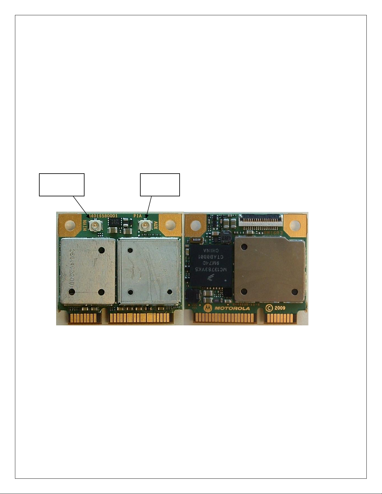
Main
Antenna
Div
Antenna
Top View Bottom View
Figure 1 -HTM 1200 Half Mini PCIe card (Top and Bottom views)
Motorola Confidential Proprietary – Disclosed Under NDA
Page 6 of 30
Page 8
HTM1200 HSPA Data Card User Manual
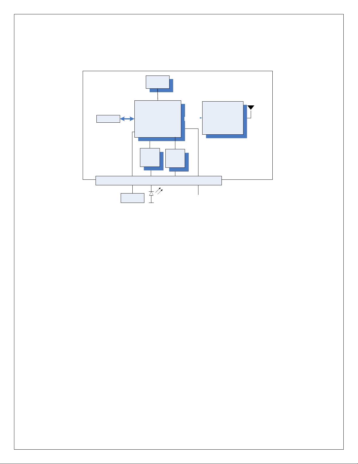
3. Hardware Architecture
EEPROM
I2C
RFIC +
Front En d +
PAs
SDRAM
SIM
Baseband
Processor
SPI
PMIC
3G DigRF
GPIO
ULPI
HSUSB
PHY
HTM1200 Datacard
PCI Express connector
USIM
WWAN LED
W_DISABLE
PC
Figure 2 HTM1200 high level block diagram
Motorola Confidential Proprietary – Disclosed Under NDA
Page 7 of 30
Page 9
HTM1200 HSPA Data Card User Manual
_
_
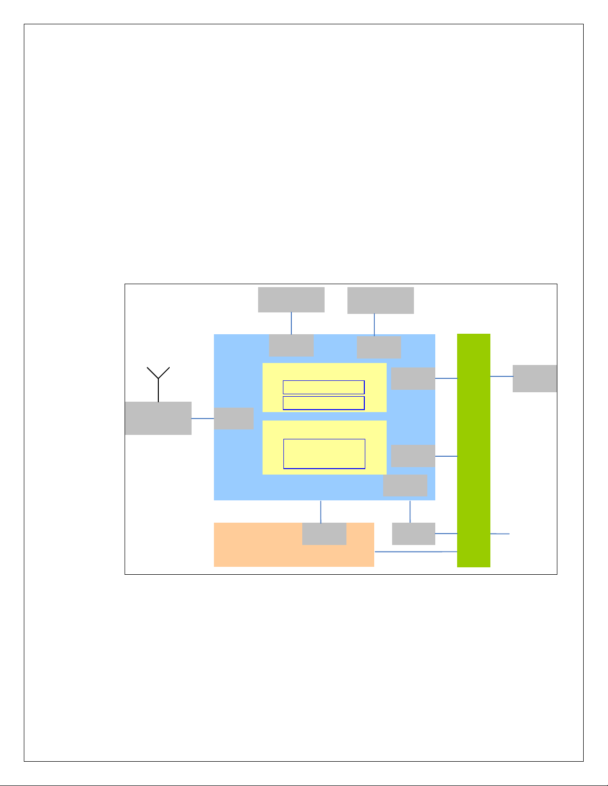
4. Software Architectur e
The HTM1200 Data Card software architecture is based on:
• Linux kernel running on the ARM9 application processor of the W3G.
• Native services running on top of the Linux kernel in the user space.
• Hardware specific adapters, drivers and software stacks.
• A 3GSM Single Core Modem architecture running on the C55x+ DSP of the
W3G.
The following diagram shows a high level overview of the software partitioning
architecture:
SmartiUEMD
RF
W 3 G
RF IF
DDR SDRAM
SDRC
ARM
Native Services
Android Kernel
C
55
2G/3
G Stack
SPI
Atlas POWER IC
9
+x
EEPROM
I2C
SIM IF
GPIO
HSUSB
OTG
USB
XVR
P
C
I
E
UICC
USB
USB
D+
D-
Figure 3 - Software Partitioning Architecture Overview
Motorola Confidential Proprietary – Disclosed Under NDA
Page 8 of 30
Page 10

HTM1200 HSPA Data Card User Manual
5. HTM1200 Data Card Feature Summary
Key capabilities for the data card and associated features of the platform are listed
below. The following summary describes some of the platform capabilities.
5.1 Hardware Revision: P1B
5.2 2G
• 3GPP Release 6 compliant
• Quad-band GSM 850/900/1800/1900 MHz
• GPRS Class 12
• EDGE Class 12, 236 kbps (UL and DL)
• A5/1-3 and GEA/1-3 Encryption
• DARP (Downlink Advanced receiver Performance)
• GSM Power Class 4 (+33 dBm for 850/900MHz), Power Class 1 (+30dBm
for 1800/1900MHz)
• EDGE Power Class E2 ( +27dBm for 850/900MHz and +26dBm for
1800/1900MHz)
• Sensitivity: -108dBm typical, nominal conditions
5.3 3G
• 3GPP Release 6 compliant
• Frequency Bands
o 2100/900 MHz (Supported)
o 2100/1900/850 MHz (Supported)
• WCDMA 384kbps uplink (UL) – 384kbps downlink (DL)
• HSDPA 7.2 Mbps
• HSUPA 1.46 / 2 / 5.76 Mbps
• UEA01, UEA02, UIA1, UIA2 Encryption
• 3G Rx Diversity in 2100 band
• Advanced Receiver Type 3i
• Power Class 3 (23 dBm)
• Sensitivity: -110dBm typical, nominal conditions
5.4 External Memory
• 32MB DDR memory is packaged on baseband processor
• 512Kb EEPROM is used to store phasing data
5.5 System Requirements
• Linux Android Kernel (K29) in the ARM9 of the W3G
• RTXC in the C55x+ of the W3G
Motorola Confidential Proprietary – Disclosed Under NDA
Page 9 of 30
Page 11
HTM1200 HSPA Data Card User Manual
5.6 Security
• High Assurance Boot with Multiple Super Root Key Support
• MD5, SHA-1, SHA-256, 3DES, AES 128, RC4, RSA
• Subsidy Lock
• IMEI Protection
5.7 Connectivity
• SIM or UICC (SIM and USIM)
• USB client 2.0 HS Support (PC connectivity)
• 3GDigRF RF interface version 3.07
5.8 Power Up and Host Boot Mechanism
The main power management function is performed by Power management IC (Atlas),
which receives its voltage input from the PCIe interface. 3.3V on PCIe interface supplies
power to PMIC. Atlas manages all data card power.
When power is applied to the data card, the W3G ROM will attempt to enumerate with
the host. If the host if not ready, it will try again to enumerate with the host every 3
seconds. After successful enumeration, the host will download bootloader to the
device. After the download, the bootloader will re-enumerate as flash interface. The
firmware application is sent to the bootloader which downloads it to RAM and runs. The
firmware application will then enumerate with 2 ACM interfaces and 2 ECM interfaces.
Description of the interfaces is provided in section 8.1.2
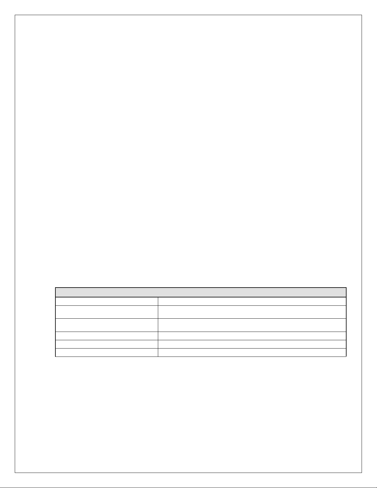
5.9 Power Consumption
Following table shows HTM1200 data card power consumption.
Typical Power
Input Supply 3.3V DC
HSDPA 7.2Mbps download +
HSUPA 5.76Mbps @ 0dBm
HSDPA 7.2Mbps download +
HSUPA 5.76Mbps @ 23dBm
EDGE 4RX 200kbps 0.65W
Idle Mode 3G (K=7, DRX length = 1.28s) < 20mW
Idle Mode 2G (DRX2) < 20mW
1.3W
2.5W
6. Mechanical Specifications
6.1.1 Electrical Specification
HTM1200 powers up using 3.3V supply on PCIe interface. The supply voltage should be
within ±9% of 3.3v.
Motorola Confidential Proprietary – Disclosed Under NDA
Page 10 of 30
Page 12

HTM1200 HSPA Data Card User Manual
6.1.2 Mechanical Specification
Physical dimensions of the card are: 30mm x 26.8mm x 4.60mm (Double sided)
Weight: 5g
Figure 4: HTM1200 Mechanical Specification
6.1.3 Thermal Specification
Operating temperature range for HTM1200 is -10oC to +65oC.
Motorola Confidential Proprietary – Disclosed Under NDA
Page 11 of 30
Page 13

HTM1200 HSPA Data Card User Manual
7. Data Card Interfaces
7.1.1 PCIe Interface
HTM1200 connects with netbook, notebook or MID using PCIe interface. HTM1200
uses USB interface on PCIe interface. Electrically the PCI Express card will be seen as a
USB device since it uses standard USB2.0 connection. Power is supplied by motherboard.
A SIM connector must be provided on the host device for user authentication.
A Radio disable (W_Disable) signal is connected from PC to the card; this allows the
user to be able to power down or power up the data card. The card controls one of the
PC’s LED to indicate RF activity has been disabled or enabled.
To summarize main characteristics of PCIe are as follows:
• Standard USB interface
• 3.3V power supply from motherboard is used. Voltage should be with in ±9%
of 3.3V.
• Max current in worst case scenario is 1.1A averaged over 1sec, 2.75A
averaged over 100µs.
• W_DISABLE is used to power down and power up HTM1200.
• PC WWAN LED is controlled by HTM1200.
The following table shows signals on PCIe interface.
PIN
Number
51
49
47
45
PCIe Spec
Reserved 52
Reserved 50
Reserved 48
Reserved 46
HTM1200
data card
Pin
Number PCIe spec
+3.3Vaux +3.3Vaux
GND GND
+1.5V
LED_WPAN
#
HTM1200
data card
LED_WLAN
#
LED_WWA
N#
GND GND
USB_D+ USB_D+
USB_D- USB_D-
GND GND
SMB_DATA
SMB_CLK
+1.5V
GND GND
LED_WWAN
43
41
39
37
35
33
31
29
27
25
GND GND 44
+3.3Vaux +3.3Vaux 42
+3.3Vaux +3.3Vaux 40
GND GND 38
GND GND 36
PETp0 34
PETn0 32
GND GND 30
GND GND 28
PERp0 26
Motorola Confidential Proprietary – Disclosed Under NDA
Page 12 of 30
#
Page 14

HTM1200 HSPA Data Card User Manual
23
21
19
17
15
13
11
9
7
5
3 COEX1 COEX1 4 GND GND
1
PERn0 24
GND GND 22
Reserved 20
Reserved 18
GND GND 16
REFCLK
+
REFCLK- 12
GND GND 10
CLKREQ
#
COEX2 COEX2 6
WAKE# 2
14
8
+3.3Vaux +3.3Vaux
PERST#
W_DISABL
E#
GND GND
UIM_VPP
UIM_RESET SIM_RESET
UIM_CLK SIM_CLK
UIM_DATA SIM_DATA
UIM_PWR SIM_PWR
1.5V
3.3Vaux +3.3Vaux
W_DISABLE
#
Table 1 – HTM1200 52-pin PCI Express connector pinout
7.1.2 SIM Interface
A standard ISO7816 SIM interface has been used on the card. SIM card is connected to
the SIM controller on ARM9.
SIM card slot must be provided by PC manufacturer. SIM signals are routed through
PCIe interface. SIM signals are shown in section 7.1.1.
SIM card must not be removed when the data card is powered up.
Motorola Confidential Proprietary – Disclosed Under NDA
Page 13 of 30
Page 15

HTM1200 HSPA Data Card User Manual
8. Hardware Installation
8.1 HTM1200 Data Card Installation
This chapter describes physical installation of data card and configuration of HTM1200
3G data card.
An extender board is used to convert half mini 3G data card to a full mini card. The
extender board is attached to 3G data card as shown in the picture below.
Top View Bottom View
Locate an available Mini PCIE V2 card slot in computer.
Motorola Confidential Proprietary – Disclosed Under NDA
Page 14 of 30
Page 16

HTM1200 HSPA Data Card User Manual
To ensure proper installation, insert the card into the slot at a 45
o
angle as shown in the
picture below.
Mini-PCIe Card
Slot
The HTM1200 must be pushed down and securely fastened in the MINI-PCIe V2 slot by
the means provided by the laptop vendor (screw or clip).
Motorola Confidential Proprietary – Disclosed Under NDA
Page 15 of 30
Page 17

HTM1200 HSPA Data Card User Manual
Vendor Screw
Fastener for Full
Mini-PCIe slot.
Connect the provided laptop antennas to the UFL connectors on the HTM1200 card. The
UFL connectors will snap down when properly connected to the HTM1200. If the Main
and Aux antennas are specified by the computer manufacturer then the antennas must be
connected accordingly.
Aux Antenna
Lead
Main Antenna
Lead
Motorola Confidential Proprietary – Disclosed Under NDA
Page 16 of 30
Page 18

HTM1200 HSPA Data Card User Manual
9. Data Card Driver Package
HTM1200 data card drivers are available for download from Motorola Extranet compass
site. The driver package is available for Windows XP and Windows 7 operating systems
in 32-bit and 64-bit format. The driver package is an msi (Microsoft Installer) package
which includes USB driver and host boot service.
9.1 Windows XP / Windows7 32-bit
9.1.1 Driver Installation
This driver is compatible with Windows XP and Windows7. AT commands must be sent to
the modem using ACM port. Details of driver configuration are shown in section 8.1.2
If HTM1200 data card is inside the host device, power down the data card until
successful installation of the driver. If the host device (PC) has previous revision of
Motorola Datacard drivers, run C:\Program Files\Common Files\Motorola
Shared\Mot3GDatacard\Motorola Driver Installer.exe, clean the driver and uninstall
before installing the new driver.
Double click on
“Motorola_HTM1200_Datacard_Drivers_1.5.4_MotoConnectCard_1.2.5.msi” to start
installation. Installation window opens, and click ‘Next’ on the window.
Motorola Confidential Proprietary – Disclosed Under NDA
Page 17 of 30
Page 19

HTM1200 HSPA Data Card User Manual
Agree to license terms, click on ‘Next’.
Motorola Confidential Proprietary – Disclosed Under NDA
Page 18 of 30
Page 20

HTM1200 HSPA Data Card User Manual
Installation complete message comes up. Click Close to exit.
The installer will ask for a system restart. Please close all other applications and click on
the “Yes” button to restart the system. After installing the driver PC must be restarted
before powering up HTM1200.
Motorola Confidential Proprietary – Disclosed Under NDA
Page 19 of 30
Page 21

HTM1200 HSPA Data Card User Manual
9.1.2 Host Boot Service
When the driver is installed host boot service starts automatic. The service is called Moto
Connect Card Service. Hostboot service is installed at C:\Program
Files\Motorola\MCC\HostBoot.
9.1.3 Connecting to Live Network in Windows XP/Windows7
Dial up networking can be used to setup live network connection.
Open device manager, right click on Motorola 3G HTM1000 Modem under modems and
choose properties. Click on ‘Advanced’ tab and enter the initialization command:
AT+CGDCONT = 1,”IP”,”APN”. Where APN is the access point name. APN
information must be obtained from the carrier that is supplying SIM card. Then click
on ’OK’ on the window to save settings.
By default the radio is turned off (Airplane Mode). Radio can be turned on by sending an
AT command to the Modem. Open HyperTerminal and connect to the modem using
Modem port. To turn ‘ON’ the radio send AT command AT+CFUN=1. This will enable
radio. If an LED is connected to WWAN_LED pin, LED will turn ON when the radio is
turned ‘ON’; this is an indication to ensure that the radio is ON.
Motorola Confidential Proprietary – Disclosed Under NDA
Page 20 of 30
Page 22

HTM1200 HSPA Data Card User Manual
Use the following steps to setup dial up connection. From StartÆSettingsÆnetwork
Connections open New Network Connection wizard and setup a new dial up network
connection.
To continue click ‘Next’
Choose “connect to the Internet” and click on ‘Next’
Choose to ‘Set up the connection manually” and click on ‘Next’
Motorola Confidential Proprietary – Disclosed Under NDA
Page 21 of 30
Page 23

HTM1200 HSPA Data Card User Manual
Choose ‘Connect using a dial-up modem” and click on ‘Next’
Choose Motorola 3G Datacard Modem and click ‘Next’
Motorola Confidential Proprietary – Disclosed Under NDA
Page 22 of 30
Page 24

HTM1200 HSPA Data Card User Manual
Enter a name for ISP and click ‘Next’
Enter phone number for data connection. The dial up number is provided by the carrier
and the number could vary from carrier to carrier. Typically the dial in number is *99# or
*99***1#. Enter the dial up number and click on ‘Next’
Motorola Confidential Proprietary – Disclosed Under NDA
Page 23 of 30
Page 25

HTM1200 HSPA Data Card User Manual
Motorola Confidential Proprietary – Disclosed Under NDA
Page 24 of 30
Page 26

HTM1200 HSPA Data Card User Manual
Now you are ready to connect to live network. Double click on 3G Data Card icon on the
desktop. 3G Data Card connection window appears as shown below.
Motorola Confidential Proprietary – Disclosed Under NDA
Page 25 of 30
Page 27

HTM1200 HSPA Data Card User Manual
Click on properties and ensure that 3G HTM1000 modem is chosen for connection. Click
on ‘OK’ on Properties window and then Click on ‘Dial’ on 3G LGA module window.
The following window appears which shows dial up connection.
Once network connection is established, IP address of the connection can be verified by
typing ‘ipconfig” in command window.
9.2 Windows XP / Windows7 64-bit
9.2.1 Driver Installation
This driver is compatible with Windows XP and Windows7.
If HTM1200 data card is inside the host device, power down the data card until
successful installation of the driver. If the host device (PC) has previous revision of
Motorola Confidential Proprietary – Disclosed Under NDA
Page 26 of 30
Page 28

HTM1200 HSPA Data Card User Manual
Motorola Datacard drivers, run C:\Program Files\Common Files\Motorola
Shared\Mot3GDatacard\Motorola Driver Installer.exe, clean the driver and uninstall
before installing the new driver.
Double click on
“Motorola_HTM1200_Datacard_Drivers_1.5.5_MotoConnectCard_1.2.5_x64.msi” to start
installation. Follow instructions from section 14.1.1 to complete driver installation.
9.2.2 Host Boot Service
When the driver is installed host boot service starts automatic. The service is called Moto
Connect Card Service. Hostboot service is installed at C:\Program Files
(x86)\Motorola\MCC\HostBoot.
9.2.3 Connecting to Live Network in Windows XP/Windows7
Dial up networking can be used to setup live network connection. Follow instructions
from section 14.2.3.
9.3 Windows 7 Mobile Broadband x86 and x64
9.3.1 Driver Installation
Double click on “Motorola_Mobile_Broadband_Driver_0.9.0.exe” to start installation. The
executable stops existing services (MCC and MotoMBService) before installing the new
driver. The executable extracts driver files and starts installation. Installation window opens,
and click ‘Next’ on the window.
Motorola Confidential Proprietary – Disclosed Under NDA
Page 27 of 30
Page 29

HTM1200 HSPA Data Card User Manual
Figure 5 Windows 7 x86 and x64 installation
Agree to license terms, click on ‘Next’.
Figure 6 License Agreement
Motorola Confidential Proprietary – Disclosed Under NDA
Page 28 of 30
Page 30

HTM1200 HSPA Data Card User Manual
Figure 7. Driver Installation in Progress
Installation complete message comes up. Click Close to exit.
Figure 8 Driver Installation Complete
Motorola Confidential Proprietary – Disclosed Under NDA
Page 29 of 30
Page 31

HTM1200 HSPA Data Card User Manual
The installer will ask for a system restart. Please close all other applications and click on
the “Yes” button to restart the system. After installing the driver PC must be restarted
before connecting HTM1200.
Figure 9 Restart PC
9.3.2 Live network Connection
Live network connection can be established using MBB connection Manager.
Motorola Confidential Proprietary – Disclosed Under NDA
Page 30 of 30
Page 32

Regulatory Requirements
Regulatory Requirements
The Federal Communications Commission (FCC) requires application for certification of digital
devices in accordance with CFR Title 47, Part 2 and Part 15. This includes MPE calculation. As
the modem is not a standalone transceiver but is an integrated module, the modem cannot be
tested by itself for EME certification. It is, however, the integrator’s responsibility to have the
completed device tested for EME certification.
Caution: Unauthorized repairs or modifications could result in permanent damage to the
equipment and void your warranty and your authority to operate this device under
Part 15 of the FCC Rules.
FCC Notice to Users
Motorola has not approved any changes or modifications to this device by the user. Any changes
or modifications could void the user's authority to operate the equipment. See 47 CFR Sec. 15.21.
This device complies with part 15 of the FCC Rules and Class B digital apparatus requirements
for ICES-003. Operation is subject to the following two conditions:
(1) This device may not cause harmful interference, and
(2) this device must accept any interference received, including interference that may cause
undesired operation. See 47 CFR Sec. 15.19(3).
The external label on the host device must include the following FCC ID information:
"This device contains TX FCC ID: IHDT56LV3"
If your mobile device or accessory has a USB connector, or is otherwise considered a computer
peripheral device whereby it can be connected to a computer for purposes of transferring data,
then it is considered a Class B device and the following statement applies:
This equipment has been tested and found to comply with the limits for a Class B digital device,
pursuant to part 15 of the FCC Rules. These limits are designed to provide reasonable protection
against harmful interference in a residential installation. This equipment generates uses and can
Page 33

radiate radio frequency energy and, if not installed and used in accordance with the instructions,
may cause harmful interference to radio communications. However, there is no guarantee that
interference will not occur in a particular installation. If this equipment does cause harmful
interference to radio or television reception, which can be determined by turning the equipment
off and on, the user is encouraged to try to correct the interference by one or more of the
following measures:
This device complies with Part 15 of the FCC Rules. Operation is subject to the following two
conditions:
(1) This device may not cause harmful interference.
(2) This device must accept any interference received, including interference that may cause
undesired operation.
Precautions
Preface
• Reorient or relocate the receiving antenna.
• Increase the separation between the equipment and the receiver.
• Connect the equipment to an outlet on a circuit different from that to which the receiver is
connected.
• Consult the dealer or an experienced radio/TV technician for help.
Interface connector and some of the module circuits are not shielded. Be sure to take appropriate
precautionary measures in order to avoid ESD while handling the module. ESD can damage the
modules. Integrators need to design ESD protection on all external interfaces.
Antenna and Transmission Safety Precautions
User Operation
Do not operate your unit when a person is within 8 inches (20 centimeters) of the antenna. A
person or object within 8 inches (20 centimeters) of the antenna could impair call quality and may
cause the phone to operate at a higher power level than necessary.
Important: The unit must be installed in a manner that provides a minimum separation distance
of 20 cm or more between the antenna and persons and must not be co-located or
operate in conjunction with any other antenna or transmitter to satisfy FCC RF
exposure requirements for mobile transmitting devices.
Important: To comply with the FCC RF exposure limits and satisfy the categorical exclusion
requirements for mobile transmitters, the requirements described in the following
section, “Antenna Installation” , must be met.
Page 34

Standards
Antenna Installation
• The antenna installation must provide a minimum separation distance of 20 cm from users
and nearby persons and must not be co-located or operating in conjunction with any other
antenna or transmitter.
• Antenna installation should be done by a professional installer and should meet all FCC
requirement as given in FCC part 15.
• The combined cable loss and antenna gain must not exceed +2.6 dBi (850 band). The
combined cable loss and antenna gain must not exceed +3.0 dBi and total system output
must not exceed 2.0W
of 24.232 (b). OEM installers must be provided with antenna installation instruction and
transmitter operating conditions for satisfying RF exposure compliance.
P in the PCS (1900) band in order to comply with the EIRP limit
EIR
Section 15.203 - Antenna Requirements
An intentional radiator shall be designed to ensure that no antenna other than that furnished by the
responsible party shall be used with the device. The use of a permanently attached antenna or of
an antenna that uses a unique coupling to the intentional radiator shall be considered sufficient to
comply with the provisions of this Section. The manufacturer may design the unit so that a
broken antenna can be replaced by the user, but the use of a standard antenna jack or electrical
connector is prohibited. This requirement does not apply to carrier current devices or to de-vices
operated under the provisions of Sections 15.211, 15.213, 15.217, 15.219, or 15.221. Further, this
requirement does not apply to intentional radiators that must be professionally installed, such as
perimeter protection systems and some field disturbance sensors, or to other intentional radiators
which, in accordance with Section 15.31(d), must be measured at the installation site. However,
the installer shall be responsible for ensuring that the proper antenna is employed so that the
limits in this Part are not exceeded.
 Loading...