

Page 1
Level 1 & 2 Service Manual
6809511A67-O
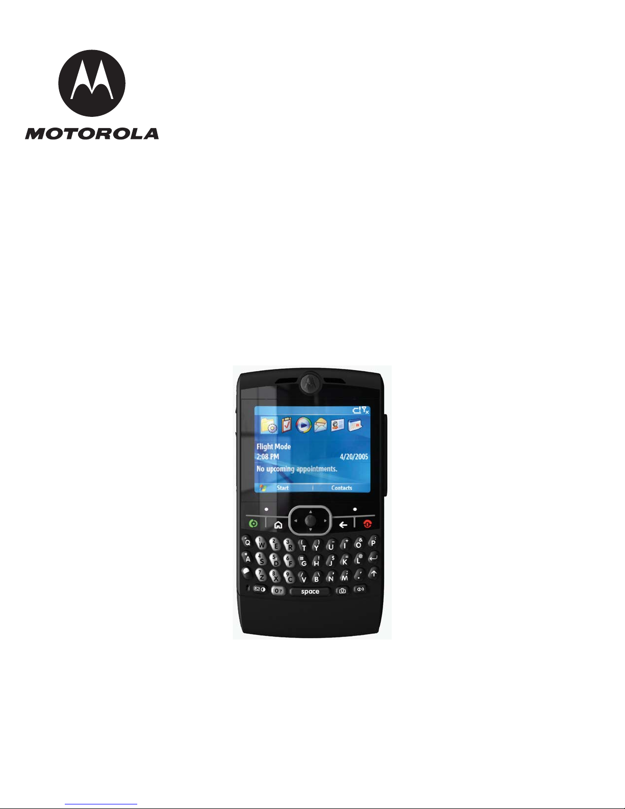
Q GSM
Digital Wireless Telephone
Q GSM 850/900/1800/1900 GPRS/EDGE
Page 2

MOTOROLA and the Stylized M Logo are registered in the US Patent & Trademark Office.
All other product or service names are the property of their respective owners.
© Motorola, Inc. 2007.
All rights reserved.
Mobile Devices Business,
Sawgrass International Concourse
789 International Parkway
Room S2C
Sunrise, FL 33325-6220
Page 3

Level Service Manual
Contents
Contents
Contents . . . . . . . . . . . . . . . . . . . . . . . . . . . . . . . . . . . . . . . . . . . . . . . . . . . . . . . . . . . . . . . . . . . . . . . . . . . . . . . . . . i
Introduction . . . . . . . . . . . . . . . . . . . . . . . . . . . . . . . . . . . . . . . . . . . . . . . . . . . . . . . . . . . . . . . . . . . . . . . . . . . . . . 1
Product Identification . . . . . . . . . . . . . . . . . . . . . . . . . . . . . . . . . . . . . . . . . . . . . . . . . . . . . . . . . . . . . . . . . 1
Product Names . . . . . . . . . . . . . . . . . . . . . . . . . . . . . . . . . . . . . . . . . . . . . . . . . . . . . . . . . . . . . . . . . . . . . . 1
Product Changes . . . . . . . . . . . . . . . . . . . . . . . . . . . . . . . . . . . . . . . . . . . . . . . . . . . . . . . . . . . . . . . . . . . . 1
Regulatory Agency Compliance . . . . . . . . . . . . . . . . . . . . . . . . . . . . . . . . . . . . . . . . . . . . . . . . . . . . . . . . . 1
Computer Program Copyrights . . . . . . . . . . . . . . . . . . . . . . . . . . . . . . . . . . . . . . . . . . . . . . . . . . . . . . . . . . 1
About This Service Manual . . . . . . . . . . . . . . . . . . . . . . . . . . . . . . . . . . . . . . . . . . . . . . . . . . . . . . . . . . . . . 2
Warranty Service Policy . . . . . . . . . . . . . . . . . . . . . . . . . . . . . . . . . . . . . . . . . . . . . . . . . . . . . . . . . . . . . . . 3
Parts Replacement . . . . . . . . . . . . . . . . . . . . . . . . . . . . . . . . . . . . . . . . . . . . . . . . . . . . . . . . . . . . . . . . . . . 4
Specifications . . . . . . . . . . . . . . . . . . . . . . . . . . . . . . . . . . . . . . . . . . . . . . . . . . . . . . . . . . . . . . . . . . . . . . . . . . . 5
Product Overview . . . . . . . . . . . . . . . . . . . . . . . . . . . . . . . . . . . . . . . . . . . . . . . . . . . . . . . . . . . . . . . . . . . . . . . . . 7
Features . . . . . . . . . . . . . . . . . . . . . . . . . . . . . . . . . . . . . . . . . . . . . . . . . . . . . . . . . . . . . . . . . . . . . . . . . . . 7
General Operation . . . . . . . . . . . . . . . . . . . . . . . . . . . . . . . . . . . . . . . . . . . . . . . . . . . . . . . . . . . . . . . . . . . . . . . . 10
Controls, Indicators, and Input/Output (I/O) Connectors . . . . . . . . . . . . . . . . . . . . . . . . . . . . . . . . . . . . . 10
Battery Information . . . . . . . . . . . . . . . . . . . . . . . . . . . . . . . . . . . . . . . . . . . . . . . . . . . . . . . . . . . . . . . . . . 13
Tools and Test Equipment . . . . . . . . . . . . . . . . . . . . . . . . . . . . . . . . . . . . . . . . . . . . . . . . . . . . . . . . . . . . . . . . . 14
Disassembly . . . . . . . . . . . . . . . . . . . . . . . . . . . . . . . . . . . . . . . . . . . . . . . . . . . . . . . . . . . . . . . . . . . . . . . . . . . . . 15
Removing and Replacing the Battery Door and Battery . . . . . . . . . . . . . . . . . . . . . . . . . . . . . . . . . . . . . 15
Removing and Replacing the Subscriber Identity Module (SIM) and Memory Card . . . . . . . . . . . . . . . . 17
Removing and Replacing the Rear Housing . . . . . . . . . . . . . . . . . . . . . . . . . . . . . . . . . . . . . . . . . . . . . . 18
Removing and Replacing the Camera Assembly . . . . . . . . . . . . . . . . . . . . . . . . . . . . . . . . . . . . . . . . . . . 21
Removing and Replacing the Transceiver Board Assembly . . . . . . . . . . . . . . . . . . . . . . . . . . . . . . . . . . 25
Removing and Replacing the Antenna . . . . . . . . . . . . . . . . . . . . . . . . . . . . . . . . . . . . . . . . . . . . . . . . . . . 28
Removing and Replacing the Display Module Assembly . . . . . . . . . . . . . . . . . . . . . . . . . . . . . . . . . . . . . 29
Subscriber Identity Module (SIM) and Identification . . . . . . . . . . . . . . . . . . . . . . . . . . . . . . . . . . . . . . . . . . . . 32
SIM . . . . . . . . . . . . . . . . . . . . . . . . . . . . . . . . . . . . . . . . . . . . . . . . . . . . . . . . . . . . . . . . . . . . . . . . . . . . . . 32
Personality Transfer . . . . . . . . . . . . . . . . . . . . . . . . . . . . . . . . . . . . . . . . . . . . . . . . . . . . . . . . . . . . . . . . . 32
Identification . . . . . . . . . . . . . . . . . . . . . . . . . . . . . . . . . . . . . . . . . . . . . . . . . . . . . . . . . . . . . . . . . . . . . . . 32
Troubleshooting . . . . . . . . . . . . . . . . . . . . . . . . . . . . . . . . . . . . . . . . . . . . . . . . . . . . . . . . . . . . . . . . . . . . . . . . . 34
Troubleshooting Chart . . . . . . . . . . . . . . . . . . . . . . . . . . . . . . . . . . . . . . . . . . . . . . . . . . . . . . . . . . . . . . . 34
Programming: Software Upgrade and Flexing . . . . . . . . . . . . . . . . . . . . . . . . . . . . . . . . . . . . . . . . . . . . . 35
Exploded View Diagram (Main assembly) . . . . . . . . . . . . . . . . . . . . . . . . . . . . . . . . . . . . . . . . . . . . . . . . 36
Exploded View Parts List (Main assembly) . . . . . . . . . . . . . . . . . . . . . . . . . . . . . . . . . . . . . . . . . . . . . . . 37
Accessories (Optional) . . . . . . . . . . . . . . . . . . . . . . . . . . . . . . . . . . . . . . . . . . . . . . . . . . . . . . . . . . . . . . . 38
Index . . . . . . . . . . . . . . . . . . . . . . . . . . . . . . . . . . . . . . . . . . . . . . . . . . . . . . . . . . . . . . . . . . . . . . . . . . . . . . . . . . . 42
March 28, 2007 i
Page 4

Contents
ii March 28, 2007
Page 5

Level 1 and 2 Service Manual
Introduction
Product Identification
Q GSM
6809511A67-O
1 and 2
Motorola® Inc. maintains a worldwide organization that is dedicated to provide responsive, fullservice customer support. Motorola products are serviced by an international network of
company-operated product care centers as well as authorized independent service firms.
Available on a contract basis, Motorola Inc. offers comprehensive maintenance and installation
programs which enable customers to meet requirements for reliable, continuous
communications.
To learn more about the wide range of Motorola service programs, contact your local Motorola
products representative or the nearest Customer Service Manager.
Motorola products are identified by the model number on a label usually located under the
battery. Use the entire model number when inquiring about the product. Numbers are also
assigned to chassis and kits. Use these numbers when requesting information or ordering
replacement parts.
Product Names
Product names are listed on the front cover. Product names are subject to change without notice.
Some product names, as well as some frequency bands, are available only in certain markets.
Product Changes
When electrical, mechanical or production changes are incorporated into Motorola products, a
revision letter is assigned to the chassis or kit affected, for example;
-A, -B, or -C, and so on.
The chassis or kit number, complete with revision number is imprinted during production. The
revision letter is an integral part of the chassis or kit number and is also listed on schematic
diagrams, and printed circuit board layouts.
Regulatory Agency Compliance
This device complies with Part 15 of the FCC Rules. Operation is subject to the following
conditions:
• This device may not cause any harmful interference, and
• this device must accept interference received, including interference that may cause undesired operation
This class B device also complies with all requirements of the Canadian Interference-Causing
Equipment Regulations (ICES-003).
Cet appareil numérique de la classe B respecte toutes les exigences du Règlement sur le matériel
brouilleur du Canada.
Computer Program Copyrights
The Motorola products described in this manual may include Motorola computer programs
stored in semiconductor memories or other media that are copyrighted with all rights reserved
worldwide to Motorola. Laws in the United States and other countries preserve for Motorola,
6809511A67-O March 28, 2007 1
Page 6

Inc. certain exclusive rights to the copyrighted computer programs, including the exclusive right
to copy, reproduce, modify, decompile, disassemble, and reverse-engineer the Motorola
computer programs in any manner or form without Motorola's prior written consent.
Furthermore, the purchase of Motorola products shall not be deemed to grant either directly or
by implication, estoppel, or otherwise, any license or rights under the copyrights, pat ents, or
patent applications of Motorola, except for a nonexclusive license to use the Motorola product
and the Motorola computer programs with the Motorola product.
About This Service Manual
Using this service manual and the suggestions contained in it assures proper installation,
operation, and maintenance of Q telephones. Refer questions about this manual to the nearest
Customer Service Manager. This manual contains mechanical service information required for
the equipment described and is current as of the printing date.
Audience
This document aids service personnel in testing and repairing Q telephones. Service personnel
should be familiar with electronic assembly, testing, and troubleshooting methods, and with the
operation and use of associated test equipment.
Q GSM
Scope
This manual provides basic information relating to Q telephones, and also to provide procedures
and processes for repairing the units at Level 1 and 2 service centers including:
• Unit swap out
• Repairing of mechanical faults
• Basic modular troubleshooting
• Testin g and verifi cation o f uni t functionality
• Initiate warranty claims and send faulty modules to Level 3 or 4 repair
centers.
2 March 28, 2007 6809511A67-O
Page 7

Level 1 and 2 Service Manual
Conventions
Special characters and typefaces, listed and described below, are used in this publication to
emphasize certain types of information.
➧
G
E
Warranty Service Policy
The product is sold with the standard 12 month warranty terms and conditions. Accidental
damage, misuse, and extended warranties offered by retailers are not supported under warranty.
Non warranty repairs are available at agreed fixed repair prices.
Out of Box Failure Policy
M
Note: Emphasizes additional information pertinent to the subject
matter.
Caution: Emphasizes information about actions which may result in
equipment damage.
Warning: Emphasizes information about actions which may result
in personal injury.
Keys to be pressed are represented graphically. For example, instead of “Press
the Menu Key”, you will see “Press
Information from a screen is shown in text as similar as possible to what
appears in the display. For example, MESSAGE.
Information that you need to type is printed in boldface type
M”.
The standard out of box failure criteria applies. Customer phones that fail very early on after the
date of sale, are to be returned to Manufacturing for root cause analysis, to guard against epidemic
criteria. Manufacturing to bear the costs of early life failure.
Product Support
Customer’s original phones will be repaired but not refurbished as standard. Appointed Motorola
Service Hubs will perform warranty and non-warranty field service for level 2 (assemblies) and
level 3 (limited PCB component). Motorola High Tech Centers will perform level 4 (full
component) repairs.
Customer Support
Customer support is available through dedicated Call Centers and in-country help desks.
Product-Service training should be arranged through the local Motorola Support Center.
6809511A67-O March 28, 2007 3
Page 8

Parts Replacement
Q GSM
When ordering replacement parts or equipment, include the Motorola part number and
description used in this service manual.
When the Motorola part number of a component is not known, use the product model number
or other related major assembly along with a description of the related major assembly and of
the component in question.
In the U.S.A., to contact Motorola, Inc. on your TTY, call: 800-793-7834.
Accessories and Aftermarket Division (AAD)
Order replacement parts, test equipment, and manuals from AAD.
U.S.A. Outside U.S.A.
Phone: 800-422-4210 Phone: 847-538-8023
F AX: 800-622-6210 F AX: 847-576-3023
Website: http://businessonline.motorola.com
EMEA
Phone: +49 461 803 1404
Website: http://emeaonline.motorola.com
Asia
Phone: +65 648 62995
Website: http://asiaonline.motorola.com
4 March 28, 2007 6809511A67-O
Page 9
Level 1 and 2 Service Manual
Specifications
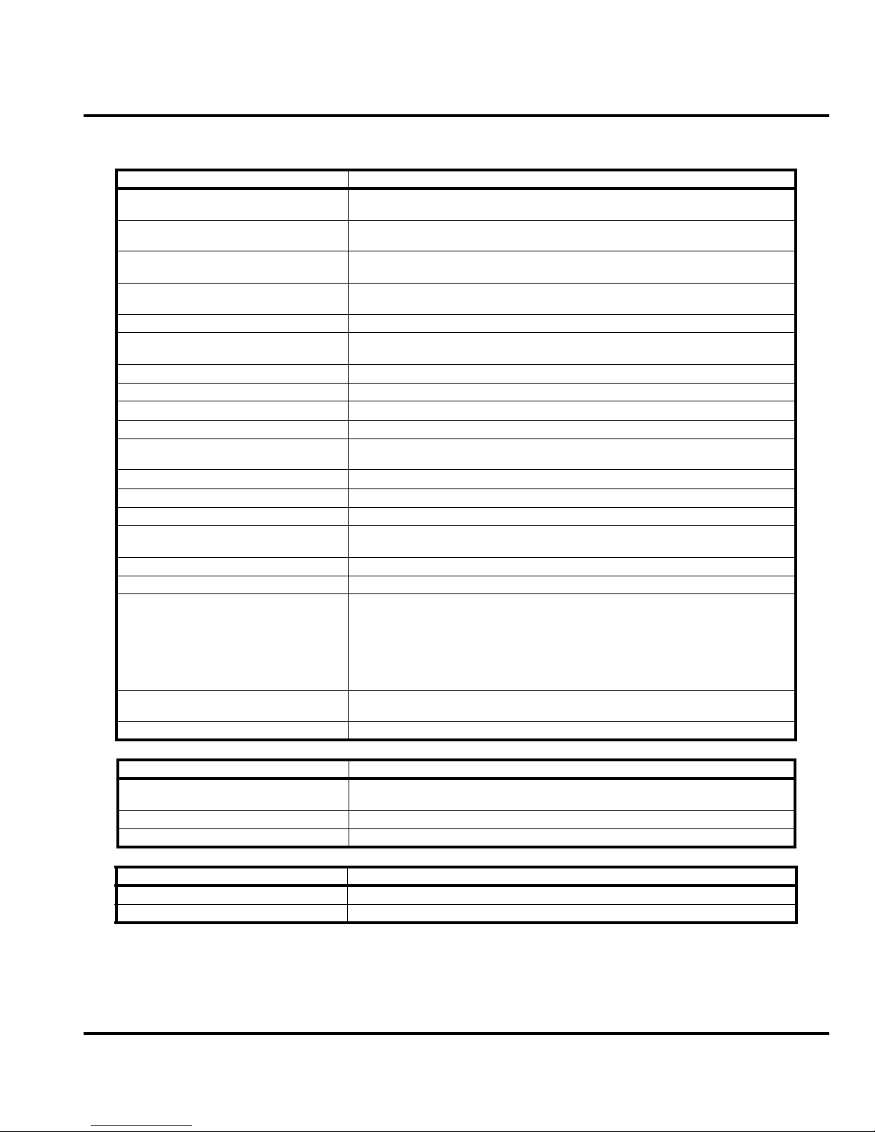
General Function Specification
Frequency Range GSM 850 824-848 MHz Tx
Frequency Range GSM 900 880-915 MHz Tx (with EGSM)
Frequency Range DCS 1800 1710-1785 MHz Tx
Frequency Range PCS 1900 1850-1910 MHz Tx
Channel Spacing 200 kHz
Channels 174 EGSM, 374 DCS, 374 PCS, 124 GSM
Modulation GMSK at BT = 0.3
Transmitter Phase Accuracy 5 Degrees RMS, 20 Degrees peak
Duplex Spacing 45 MHz
Frequency Stability ± 0.10 ppm of the downlink frequency (Rx)
Operating Voltage +3.4V dc to +4.2V dc (battery)
Transmit Current Drain 101-260 mA average talk current drain
Stand-by Current drain 4.6 mA (DRX2), 4 mA (DXR9) typical
Temperature Range -10° C to +55° C (+15° F to +130° F)
Dimensions, with 1170 mAh Li Ion
battery
Size (Volume) 85 cc, with battery
Weight 115 grams with battery
Battery Life, with standard 1170 mAh Ion
Battery
Battery Charge Time 4 hours to 90% of 1070 mAh capacity on mid-rate
Alert volume Max 95 dB @5cm, 0.5 Watts input
869-893 MHz Rx
925-960 MHZ Rx
1805-1880 MHz Rx
1930-1990 MHz Rx
with 8 channels per carrier
+5.0V dc (external connector)
117 x 64 x 11.5 (in mm)
Talk Time 300 to 420 minutes with 50 % VAF and DTX ON
Standby time 230 in DRx 2 and 270 hours in DRx 9
All talk and standby times are approximate and depend on
network configuration, signal strength, and features selected.
Standby times are quoted as a range from DRX=2 to DRX=9.
Talk times are quoted with 50 % VAF and DTX ON
2 hours to 90% of 1070 mAh capacity on fast-rate
T r ansmitter Functions Specification
RF Power Output 32 dBm nominal GSM 850 abd 900 bands, 29 dBm nominal GSM 1800 and GSM
Output Impedance 50 ohms nominal
Spurious Emissions -36 dBm from 0.1 to 1 GHz, -30 dBm from 1 to 4 GHz
Receiver Functions Specification
Receive Sensitivity Better than -103 dBm
RX Bit Error Rate (100k bits) Type II < 2%
6809511A67-O March 28, 2007 5
1900 bands
Page 10
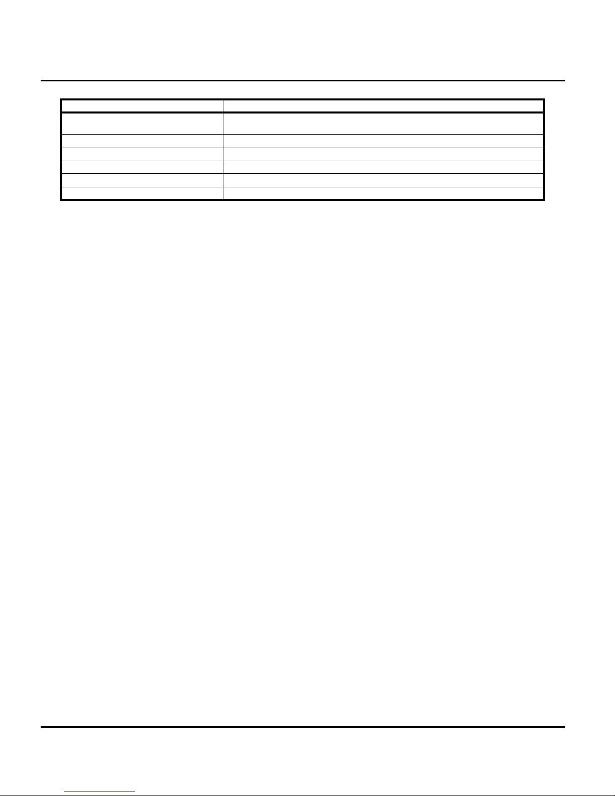
Speech Coding Functions Specification
Speech Coding Type Regular pulse excitation/linear predictive coding with long term
prediction (RPE LPC with LTP)
Bit Rate 13.0 kbps
Frame Duration 20 ms
Block Length 260 bits
Classes Class 1 bits = 182 bits; Class 2 bits = 78 bits
Bit Rate with FEC Encoding 22.8 kbps
Q GSM
6 March 28, 2007 6809511A67-O
Page 11

Level 1 and 2 Service Manual
Product Overview
Motorola Q telephones deliver GSM features in a small and lightweight package. These Global
System for Mobile communications (GSM) General Packet Radio Service (GPRS) Enhanced
Data Rates for GSM Evolution (EDGE) & Wireless Application Protocol (WAP)-enabled
mobile phones incorporate an icon based User Interface (UI) for easier operation, allows Short
Message Service (SMS) text messaging, Multi-media Messaging Services (MMS), and includes
Personal Information Manager (PIM) functionality. Q is a quad-band phones that allow roaming
within the GSM 850 MHz, GSM 900 MHz, 1800 MHz Digital Cellular System (DCS), and PCS
1900 MHz bands.
Q telephones have a tablet form factor. They feature viewable 2.4“ 240 x 320 TFT, 64k color
display for caller identification with date/time. The bottom part of the tablet contains the keyp ad,
transceiver printed circuit board (PCB), microphone, flex connection, external accessory
connector, smart button, volume buttons, and voice button. The standard 1170 mAh Lithium Ion
(Li Ion) battery fits behind a removable back cover and provides up to 300 minutes of talk time
and 192 hours of standby time in GSM mode.
The phone accepts 3V Subscriber Identity Module (SIM) cards that fit into the SIM holder under
the battery. The phone also incorporates an internal designed antenna. Inexpensive direct
connection to a computer or handheld device through USB for data and fax calls, and for
synchronizing phonebook entries with Motorola mobile Phone Tools™ software, can be
accomplished using the optional data cable and soft modem.
Features
Q telephones use advanced, self-contained, sealed, custom integrated circuits to perform the
complex functions required for GSM/GPRS communication. Aside from the space and weight
advantage, microcircuits enhance basic reliability, SIMplify maintenance, and provide a wide
variety of operational functions.
Other features available in this family of telephones include:
• GSM/GPRS/EDGE 850/900/1800/1900 MHz
• Bluetooth Class 2
• GPRS Class 10
• EDGE Class 10
Physical
• Width 64 mm
• Height 117 mm
• Depth 11.5 mm
• Volume 85 cc
• Weight 115.0 grams
Audio
• AAC
•MP3
•WMA
•WAV
6809511A67-O March 28, 2007 7
Page 12

Video
• MPEG4 Video clip playback
• H.263
•WMV
Display
• 2.4“ 240 x 320 TFT, 64k colors
Memory
• 64 MB internal memory
• Accepts removable microSD memory up to 2GB modules
Imaging
• Primary camera resolution 1.3 MP
Wireless Access Protocol (WAP) 2.0 Compliancy
Q GSM
➧
➧
In the WAP environment, access to the Internet is initiated in wireless markup language (WML),
which is derived from hypertext markup language (HTML). The request is passed to a WAP
gateway which retrieves the information from the server in standard HTML (subsequently
filtered to WML) or directly in WML if available. The information is then passed to the mobile
subscriber via the mobile network.
Bitmap image data will download as text. If the image is larger than the screen, only part of
the image will display.
If the user receives a call while in browser mode, the browser will pause and allow the user to
resume after completing the call.
SIM Toolkit™ - Class 2
SIM Application Toolkit is a value-added service delivery mechanism that allows GSM
operators to customize the services they offer their customers, from the occasional user who
requests sports news and traffic alerts, to a high call time business user who receives stock alerts
and checks flight times. Operators can now create their own value-added services menu quickly
and easily in the phone. The customized menu will appear as the first menu and may be updated
over-the-air with new services when customers request them.
Simplified Text Entry
iTAP™ predictive text entry. Press a key to generate a character and a dynamic dictionary uses
this to build and display a set of word or name options. The iTAP™ feature may not be available
on the phone in all languages.
Caller Line Identification
Upon receipt of a call, the calling party’s phone number is compared to the phone book. If the
number matches a phone book entry, that name will be displayed. If there is no phone book
8 March 28, 2007 6809511A67-O
Page 13

Level 1 and 2 Service Manual
entry, the incoming phone number will be displayed. In the event that no caller identification
information is available, an incoming call message is displayed.
➧
User must subscribe to a caller line identification service through their service provider.
Personal Information Management
The Q telephone contains a built in calendar with date book remi nders and phonebook that can
be synchronized easily to a computer.
6809511A67-O March 28, 2007 9
Page 14
General Operation
Controls, Indicators, and Input/Output (I/O) Connectors
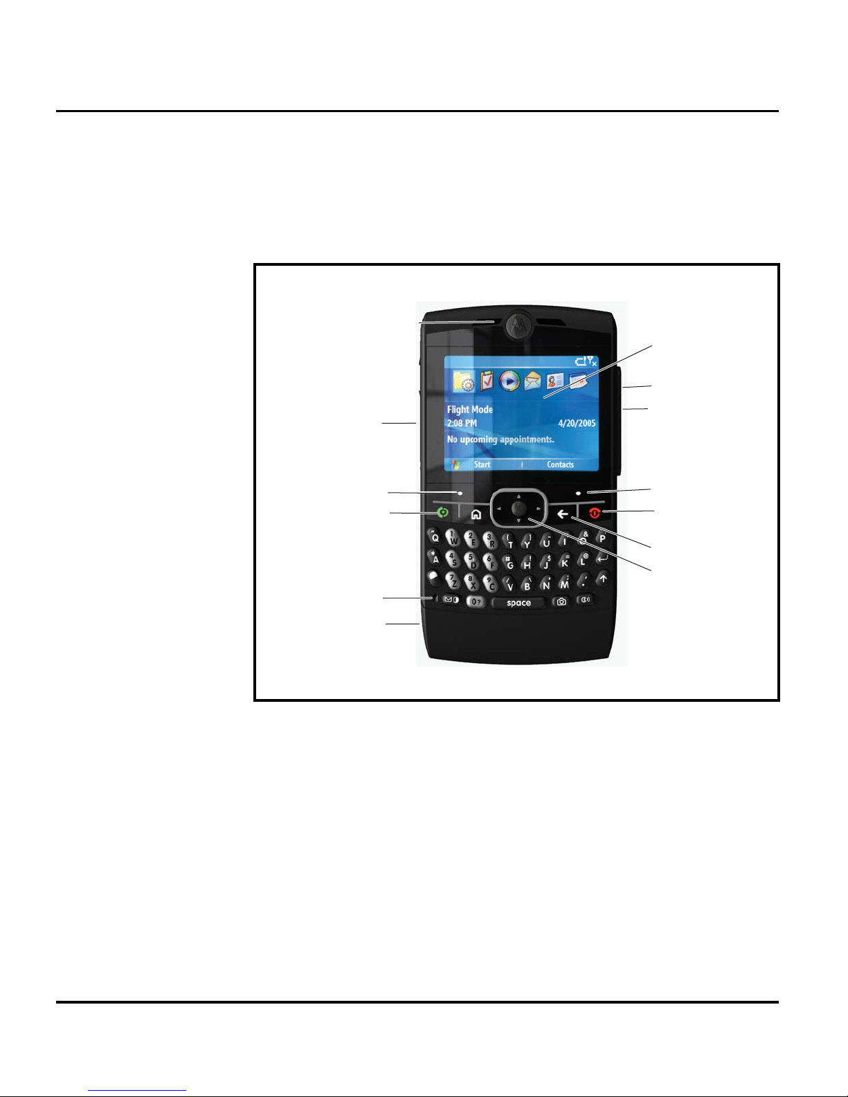
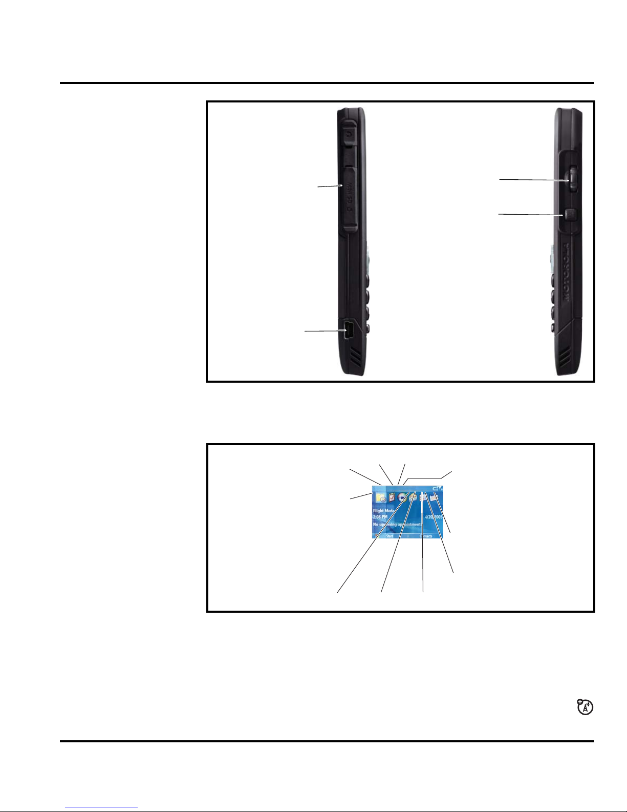
The Q controls are located on the front and sides of the device, and on the keyboard, as shown
in Figures 1 and 2.
Internal Earpiece
SD card slot
Q GSM
Main Display
Volume / Scroll Wheel
Back Key
Right Soft Key
Left Soft Key
Make & answer calls.
Mic
Charge up or connect.
Figure 1. Telephone Controls, indicators, and I/O Connections
Right Soft Key
Turn on & off, hang up,
exit menus.
Back Key
Scroll up, down,
left, or right.
Press in to select.
061418o
10 March 28, 2007 6809511A67-O
Page 15
Level 1 and 2 Service Manual
Volume / Scroll Wheel
SD Card slot
Back Key
EMU Connector
061419o
Figure 2. Telephone Controls and Indicators Locations (Sides)
Indicators, in the form of icons, are displayed on the LCD (see Figure 3).
2. GPRS
1. Signal
Strength/
Airplane
Mode
6.
3. Bluetooth
Message Location8.Profile
7.
4. Messaging
Presence
10 . Battery
5.
IM
Level
9. Active
Line
061420o
Figure 3. Main Screen Icon Display
1. Signal Strength/Airplane Mode Indicator – Vertical bars show the strength of the
network connection. You can’t make or receive calls when the no signal indicator
0 or
airplane mode indicator A shows. The roam indicator (1 or 2) shows when your phone
is seeking or using a network outside your home network.
2. GPRS Indicator – Shows when your phone is using a high-speed General Packet
Radio Service (GPRS) network connection. Indicators can include:
6809511A67-O March 28, 2007 11
Page 16
Q GSM
>
= GPRS
connection
<
= GPRS data
transfer
3. Bluetooth Indicator – Shows when your phone is connected to another device in a
Bluetooth connection.
4. Messaging Presence Indicator – Shows your instant messaging (IM) status. Indi-
cators can include:
B
= online
C
= busy
D
= invisible to IM
5. IM Indicator – Shows when you receive a new IM message.
6. Message Indicator – Shows when you receive a new text or voicemail message.
7. Profile Indicator – Shows the profile setting.
)
= normal
S
= vibrate
O
= silent
(
= meeting
8
= GPRS secure
data transfer
9
= GPRS
unsecure data
transfer
E
= offline
F
= discrete
A
= airplane
(
= sleeping
N
= active
)
= car
8. Active Line Indicator – Shows X to indicate an active call, or Y to indicate when
call forwarding is on. Indicators for dual-line-enabled SIM cards can include:
V
= line 1 active
Z
= line 1 call
forward on
9. Battery Level Indicator – Vertical bars show the battery charge level. Recharge the battery
when your phone shows Low Battery.
W
= line 2 active
a
= line 2 call
forward on
Menu Navigation
Q telephones are equipped with an icon and graphical-based user interface. All of the phone’s
features can be accessed with a 5-way navigation key that allows you to move easily through
menus and select menu items.
Liquid Crystal Display (LCD)
The LCD provides an large color display with user-adjustable brightness settings for optimum
readability in all light conditions. The large 2.4“ 240 x 320 TFT, 64k color display provides
room for entering text, viewing graphics, tapping icons, and system prompts.
Whether a phone displays all indicators depends on the programming and services to which
➧
the user subscribes.
12 March 28, 2007 6809511A67-O
Page 17
Level 1 and 2 Service Manual
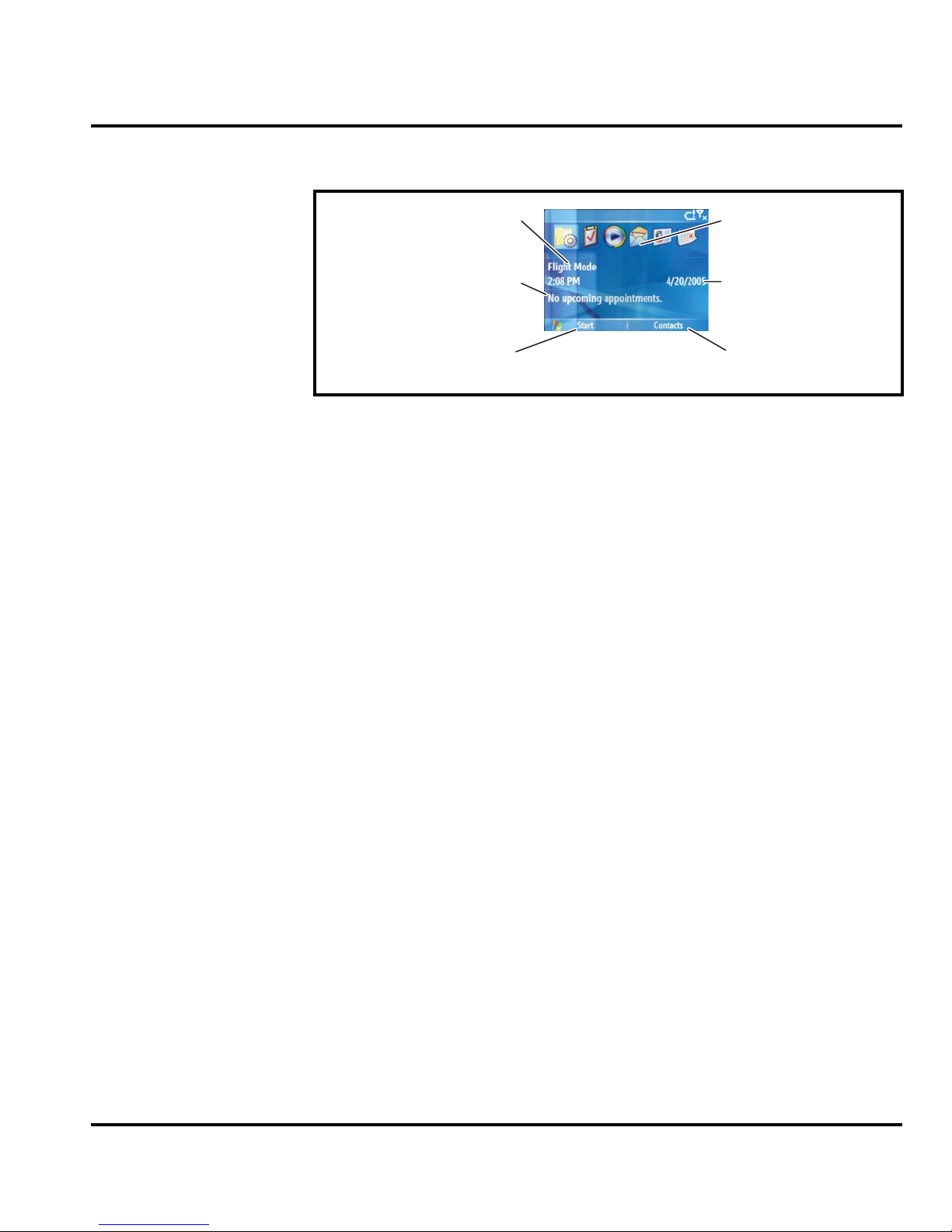
Figures 4 shows the Idle Screen display.
Battery Information
Recent Calls
Calendar Messages
Left Soft Key
Label
Figure 4. Main Screen Display
Battery Charge Indicator
The telephone displays a battery charge indicator icon in the idle screen to indicate the battery
charge level. The gauge shows four levels: 100%, 50%, 30%, 15% and Low Battery.
Battery Removal
Removing the battery causes the device to immediately shut down and any pending work
(partially entered phone book entries or outgoing messages, for example) is lost.
Messages
Date
Right Soft
Key Label
061421o
E
G
➧
All batteries can cause property damage and/or bodily injury, such as burns if a
conductive material, such as jewelry, keys, or beaded chains touch exposed terminals. The conductive material may complete an electrical circuit (short circuit) and
become quite hot. Exercise care in handling any charged battery, particularly when
placing it inside a pocket, purse, or other container with metal objects.
If the battery is removed while receiving a message, the message will be lost.
To ensure proper memory retention, turn the phone OFF before removing the
battery.
6809511A67-O March 28, 2007 13
Page 18
Q GSM
Tools and Test Equipment Q GSM
6809511A67-O
1 and 2
Tools and Test Equipment
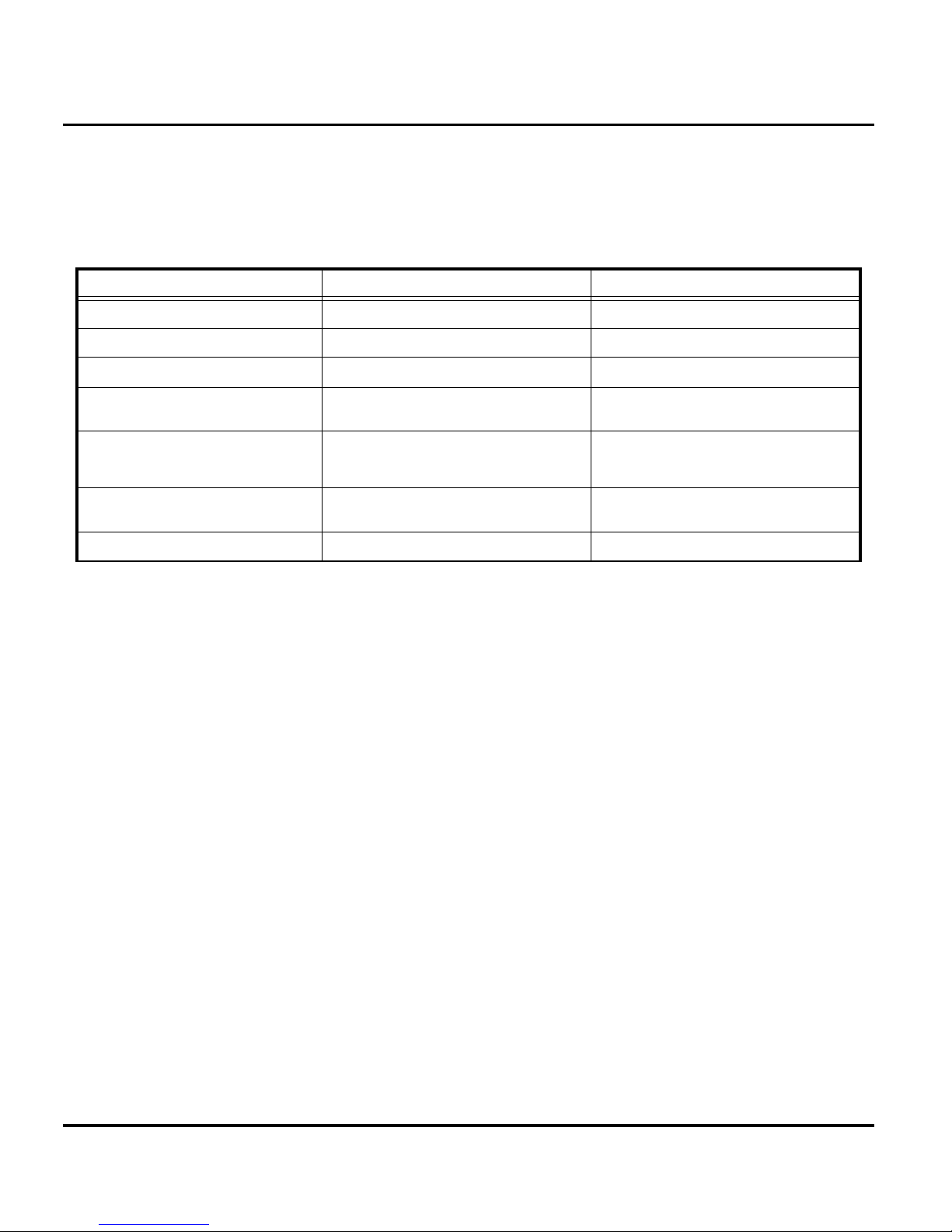
The following table lists tools and test equipment recommended for disassembly and reassembly
of Q telephones. Use either the listed items or equivalents.
Table 1. General Test Equipment and Tools
Motorola Part Number
0-00-00-40810 (U)SIM test card Used to enable manual test procedures.
RSX4043-A Torque Driver Used to remove and replace screws
— Torque Driver Bit T-6 Used with torque driver
1
Description Application
See Table 7 Rapid Charger
0180386A82
0-00-00-30005 (AMS)
19501980 (AMS)
1. To order in North America, contact Motorola Aftermarket and Accessories Division (AAD) at (800) 422-4210 or
FAX (800) 622-6210; Internationally, AAD can be reached by calling (847) 538-8023 or faxing (847) 576-3023.
2. Not available from Motorola. To order, contact: AMS Software & Elektronik GmbH, c/o Holger Grube, Lise-MeitnerStraße9 D-24941 Flensburg Tel.: +49-461-90398-0 Fax: +49-461-90398-50.
2
2
Antistatic Mat Kit (includes 66-80387A95
antistatic mat, 66-80334B36 ground
cord, and 42-80385A59 wrist band)
Disassembly tool, plastic with flat and
pointed ends (manual opening tool)
Generic press tool Used to assemble the main lens.
Used to charge battery and to power
device
Provides protection from damage to
device caused by electrostatic discharge
(ESD)
Used during assembly/disassembly of
device
14 March 28, 2007 6809511A67-O
Page 19
Level 1 and 2 Service Manual Disassembly
Disassembly
The procedures in this section provide instructions for the disassembly of a Q telephone. Tools
and equipment used for the phone are listed in Table 1, preceding.
Many of the integrated devices used in this equipment are vulnerable to damage
G
G
Removing and Replacing the Battery Door and Battery
E
from electrostatic discharge (ESD). Ensure adequate static protection is in place
when handling, shipping, and servicing the internal components of this equipment.
Avoid stressing the plastic in any way to avoid damage to either the plastic or
internal components.
All batteries can cause property damage and/or bodily injury, such as burns if a
conductive material, such as jewelry, keys, or beaded chains touch exposed terminals. The conductive material may complete an electrical circuit (short circuit) and
become quite hot. Exercise care in handling any charged battery, particularly when
placing it inside a pocket, purse, or other container with metal objects.
1. Ensure the phone is turned off.
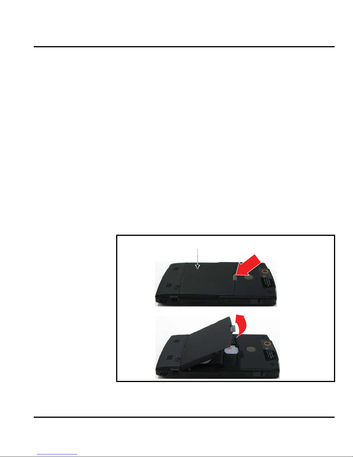
2. Press and slide the battery cover, as shown in Figure 1.
battery
cover
battery cover latch
Figure 1. Removing the Battery Door
3. Lift the battery cover completely off the phone.
6809511A67-O March 28, 2007 15
061422o
Page 20
Disassembly
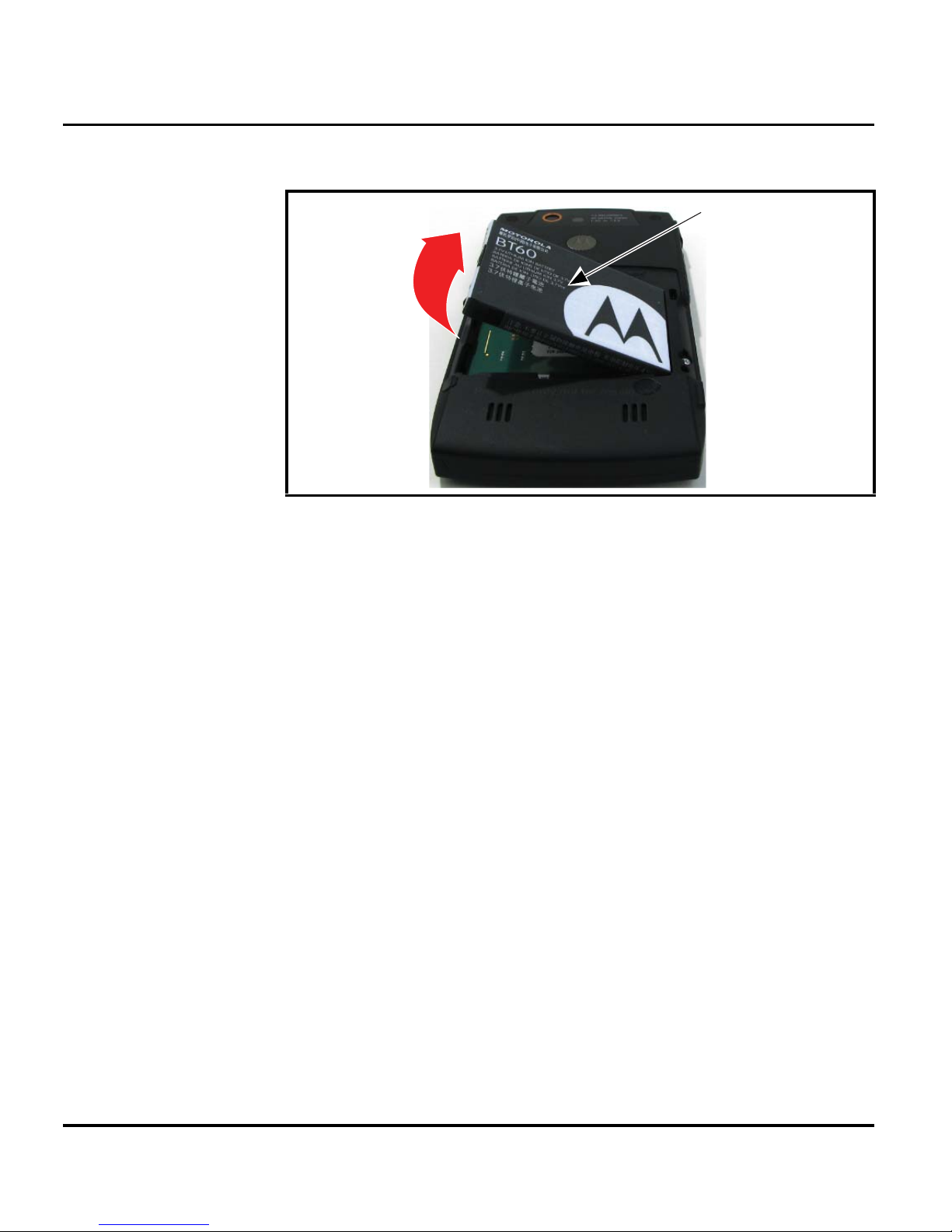
4. Lift the end of the battery and remove it completely. See Figure 2.
Batte
ry
061423o
Figure 2. Removing the Battery
E
There is a danger of explosion if the Lithium Ion battery is replaced incorrectly.
Replace only with the same type of battery or equivalent as recommended by the
battery manufacturer. Dispose of used batteries according to the manufacturer’s
instructions.
5. To replace, Align the battery with the battery compartment so the contacts on the battery
match the battery contacts in the phone.
6. Insert the battery, contacts side first, into the battery compartment and push down.
7. Insert the ridge at the bottom of the battery housing into the base of the phone, then push
the cover down and snap it into place.
16 March 28, 2007 6809511A67-O
Page 21
Level 1 and 2 Service Manual Disassembly
Removing and Replacing the Subscriber Identity Module (SIM) and Memory Card
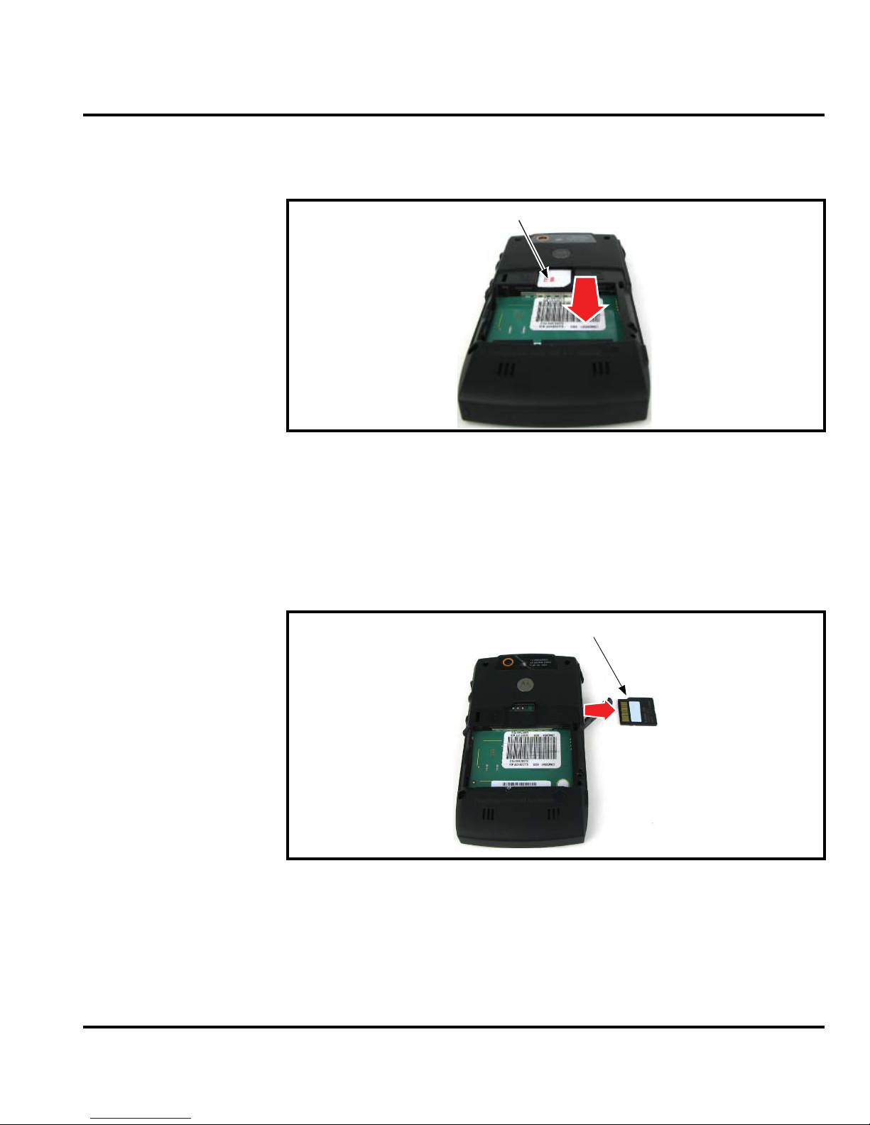
1. Remove the battery door and battery as described in the procedures.
SIM
061424o
Figure 3. Removing the SIM
2. Slide the SIM away from the SIM holder, as shown in Figure 3.
3. Carefully lift the SIM from the phone.
4. To replace, insert the SIM into the holder, ensuring the keyed corner of the SIM card should
align with alignment groove.
5. Replace the battery and battery door as described in the procedures.
6. Slide the memory card away from the memory card holder.
Mini SD
061424o
Figure 4. Removing the Memory Card
7. Carefully lift the memory card from the phone.
8. To replace, insert the memory card into the holder, ensuring the keyed corner of the memory
9. Replace the battery and battery door as described in the procedures.
6809511A67-O March 28, 2007 17
card faces the top edge of the phone.
Page 22
Disassembly
Removing and Replacing the Rear Housing
This product contains static-sensitive devices. Use anti-static handling procedures
G
G
to prevent electrostatic discharge (ESD) and component damage.
1. Remove the battery cover, battery, SIM and memory card as described in the procedures.
2. Remove and save the 3 screw grommets covering the housing screws.
In addition to 4 screws, the rear housing assembly is fastened with plastic latches.
These are fragile and should be released with care.
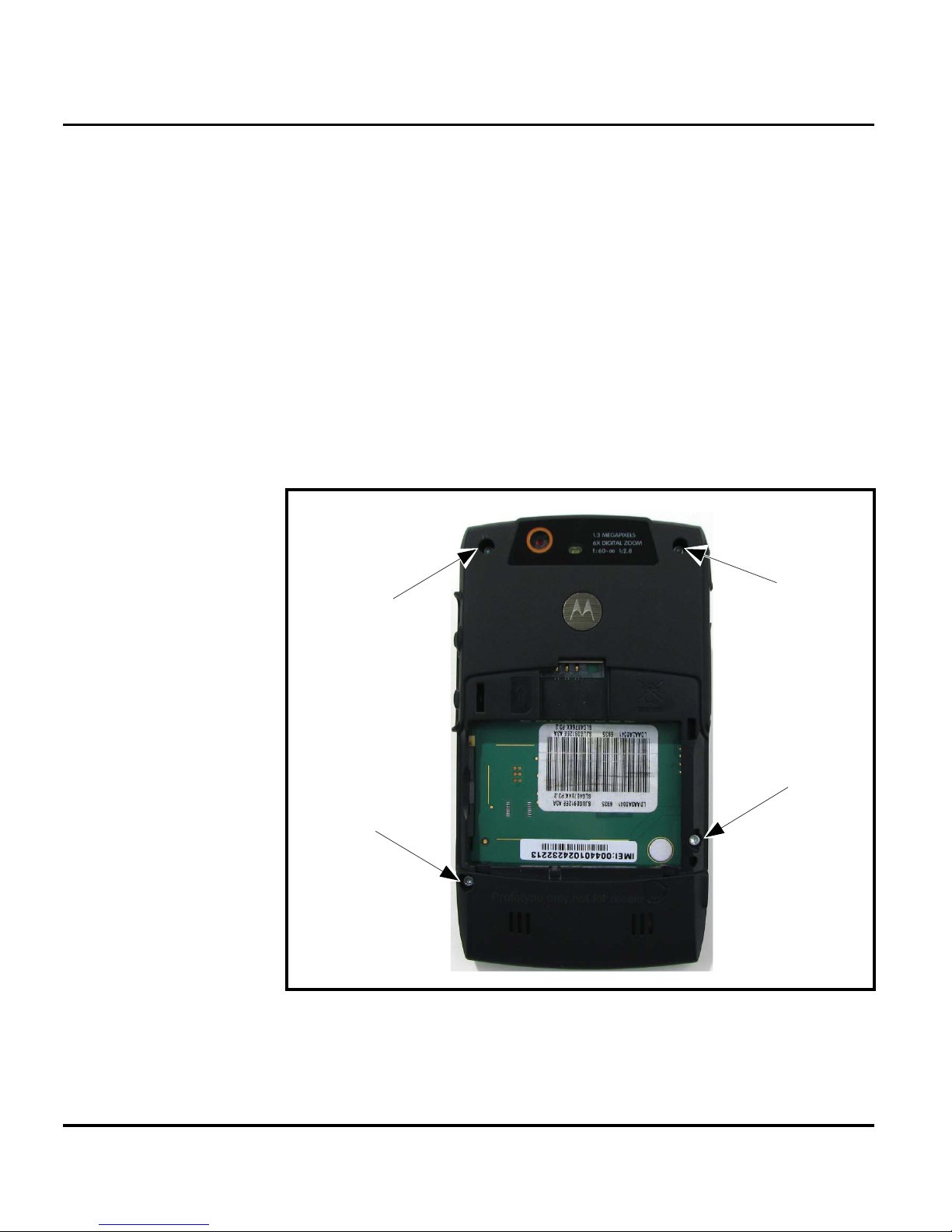
3. Using a Torx driver with a T-6 bit, remove the screws at each side of the phone. Retain the
screws for reassembly. See Figure 5.
Housing Screw
Housing Screw
Figure 5. Removing the Rear Speaker Housing Screws
Housing Screw
Housing Screw
061425o
18 March 28, 2007 6809511A67-O
Page 23
Level 1 and 2 Service Manual Disassembly
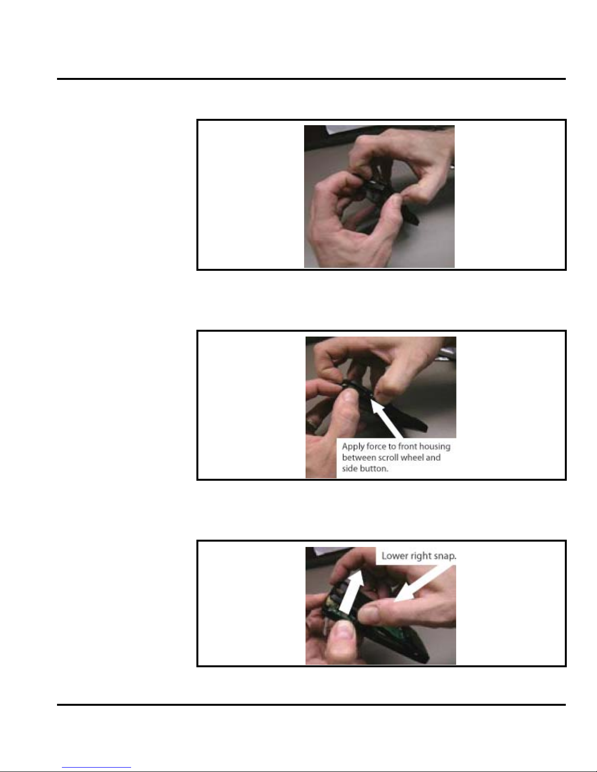
4. Open the top snap by seperating the front housing from the back housing.
061425o
Figure 6. Seperating the Front Housing from the Back H ousing
5. Un-snap the side snap by the scroll wheel by pressing on the front housing.
Figure 7. Removing the Scroll Wheel
6. Apply side force on the rear housing to disengage the lower right snap.
Figure 8. Disengaging the Lower Right Snap
6809511A67-O March 28, 2007 19
061425o
061425o
Page 24
Disassembly
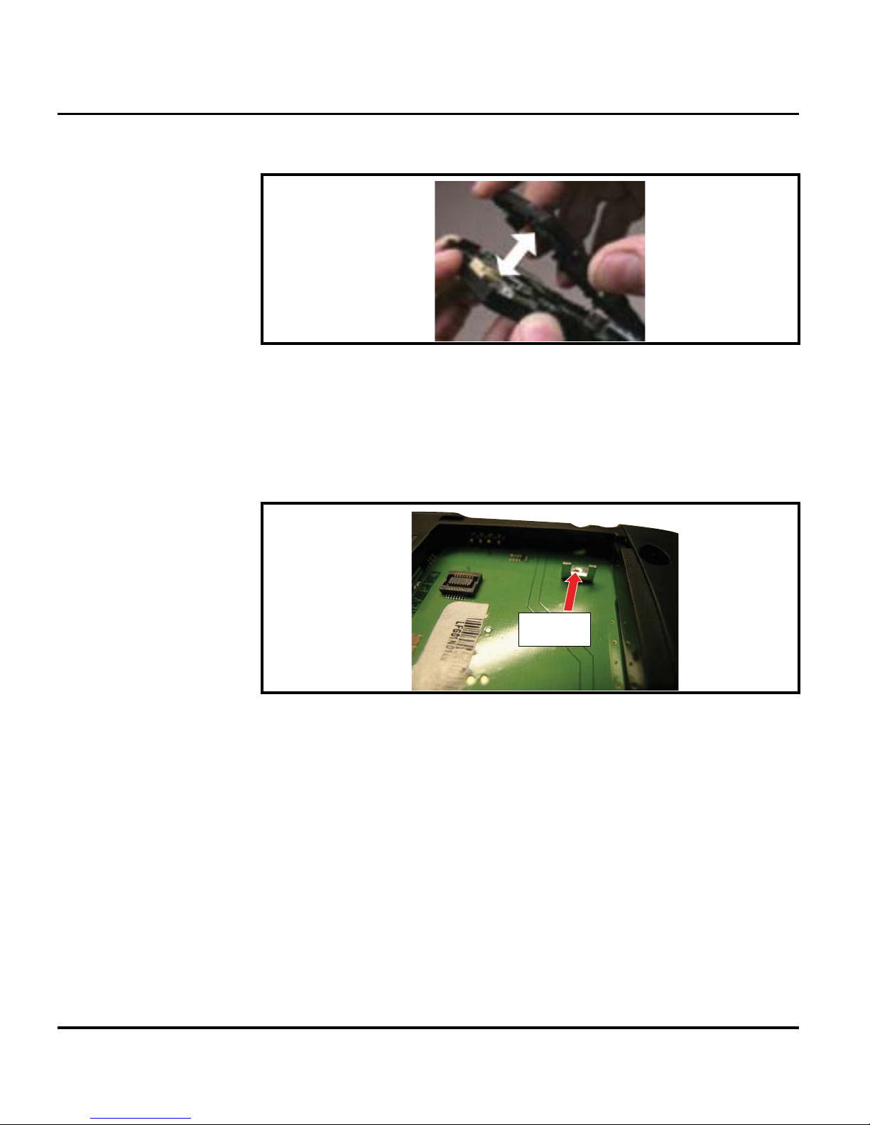
7. Finish separating the housing as shown below.
061425o
Figure 9. Separating the Housing
8. Carefully rotate the rear housing away from the front housing assembly.
9. Lift the rear housing assembly away from the phone.
10. To replace the housing assembly take notice that he lower right screw does not fasten to a
screw insert, but rather a locking bracket, a small "L" shaped stamped metal part. This will
come loose once the screw is loosened. Postion the bracket before replacing the housing.
Slide locking
bracket into this
location as shown.
061425o
Figure 10. Locking Bracket Positioning
11. Carefully align the rear housing to the front assembly.
12. Gently press the housings together until they fit snuggly.
13. Replace the 4 housing screws and tighten to a final torque setting of 2.2 +/- 0.2 lbs. Do not
over tighten.
14. Replace the SIM, memory card, battery, and battery cover as described in the procedures.
20 March 28, 2007 6809511A67-O
Page 25
Level 1 and 2 Service Manual Disassembly
r
Removing and Replacing the Camera Assembly
1. Remove the battery cover, battery, SIM, and rear housing as described in the procedures.
The flexible printed cable (FPC) (flex) is easily damaged. Exercise extreme care when
G
handling.
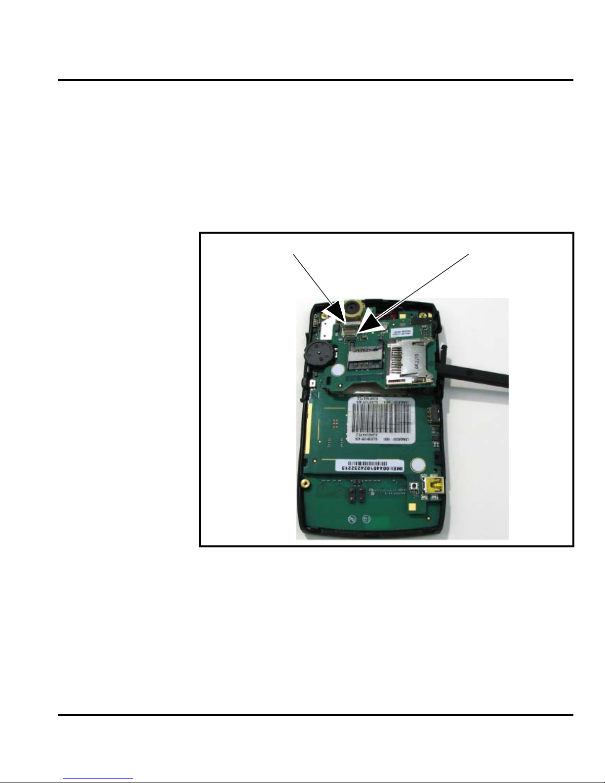
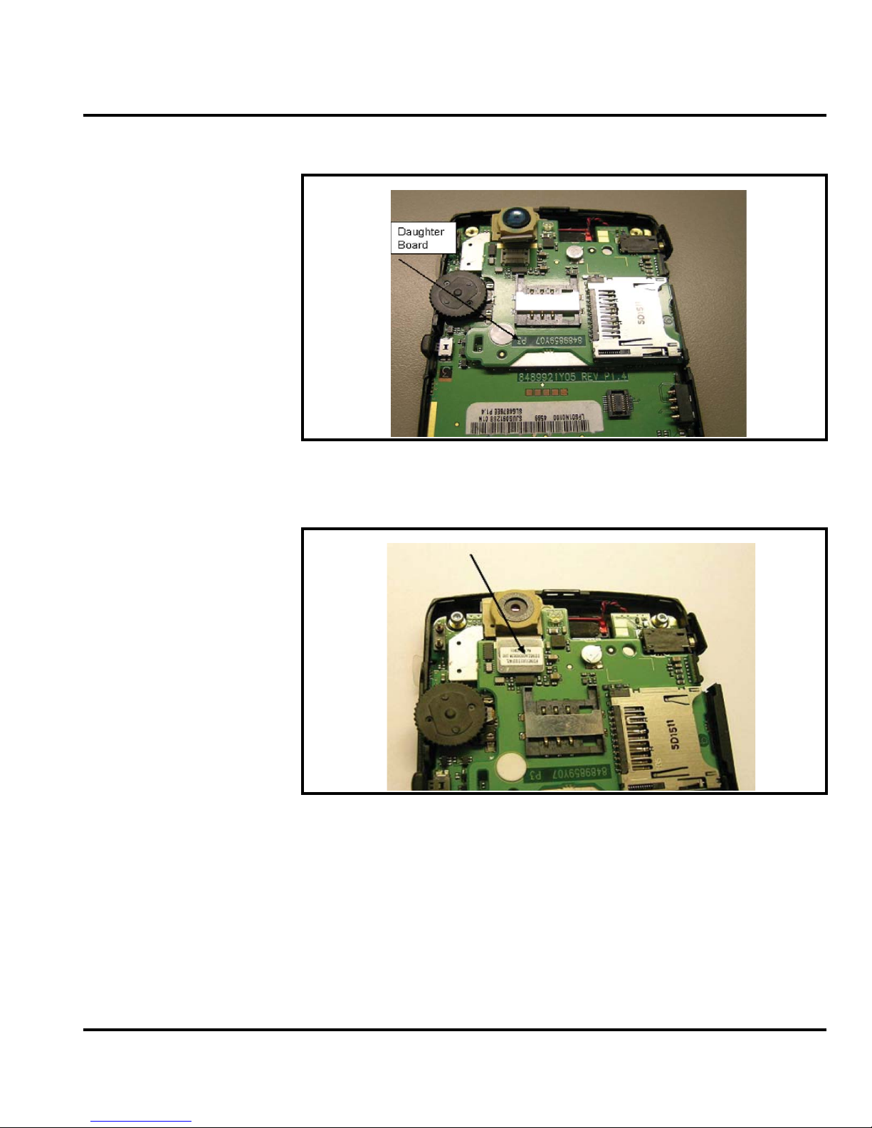
2. Use the disassembly tool to unlock the camera flex connector from the daughter board.
3. Use the disassembly tool to remove the daughter board.
Camera Flex
Flex Connecto
Figure 11. Removing the Daughter Board
6809511A67-O March 28, 2007 21
061469o
Page 26
Disassembly
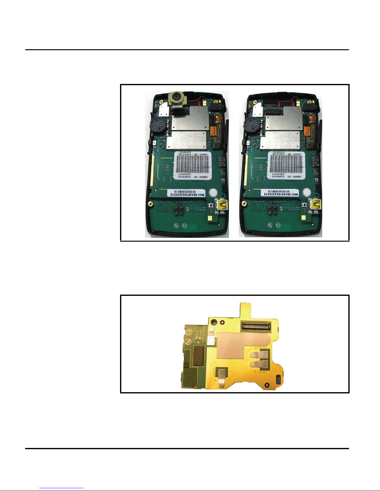
4. Remove conductive gasket then unlock the flex connector.
5. Using the disassembly tool and the plastic tweezers, remove the camera assembly.
Figure 12. Camera Assembly Removal
6. To replace, carefully insert the camera assembly into its slot in the front housing assembly,
making sure the camera grommet is placed onto the plastic guide pin.
7. Apply adhesive to daughter board.
Figure 13. Camera Assembly Removal
22 March 28, 2007 6809511A67-O
Page 27
Level 1 and 2 Service Manual Disassembly
8. Place the daughter board onto the main board.
Figure 14. Camera Assembly Removal
9. Attach the camera flex by seating the flex cable, then press firmly until it snaps into place.
Figure 15. Camera Assembly Placement
6809511A67-O March 28, 2007 23
Page 28
Disassembly
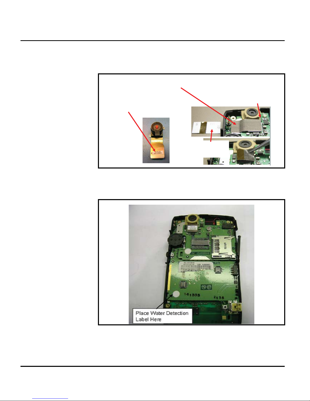
10. Place the camera assembly back into the front housing. Connect the camera flex cable to
the daughter board. After connecting the camera flex, apply the conductive gasket as shown
below.
Apply conductive gasket as shown.
Align gasket to
edges of
Place the tape over the label on
the camera connector.
This section is
placed on camera
connector.
connector.
Figure 16. Camera Assembly Placement
11. Place water detect label in location shown.
Figure 17. Camera Assembly Removal
12. Replace the rear housing, SIM, battery, and battery cover as described in the procedures.
24 March 28, 2007 6809511A67-O
Page 29
Level 1 and 2 Service Manual Disassembly
Removing and Replacing the Transceiver Board Assembly
This product contains static-sensitive devices. Use anti-static handling procedures
G
to prevent electrostatic discharge (ESD) and component damage.
1. Remove the battery cover, battery, SIM, and rear housing as described in the procedures.
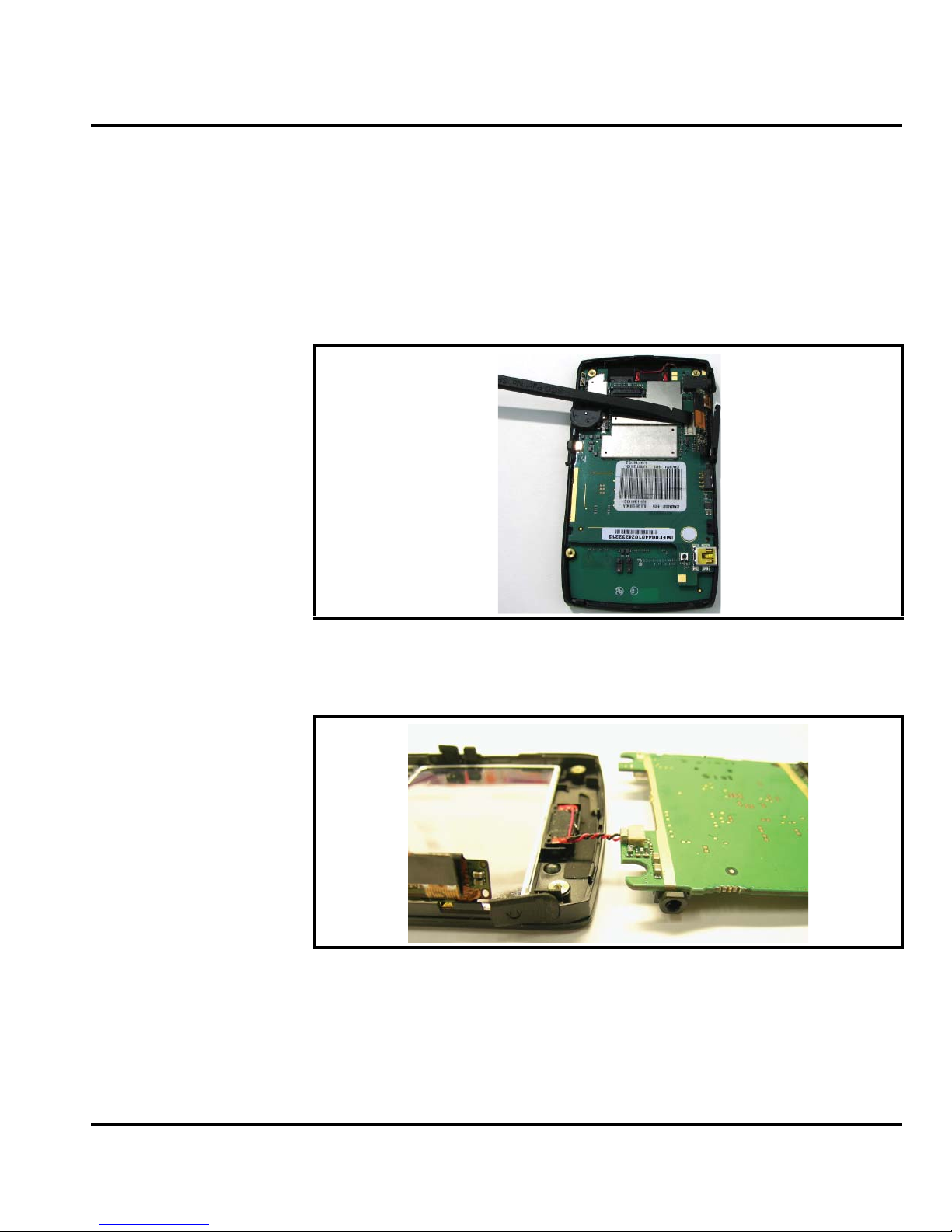
2. Use the disassembly tool to pry loose the display flex connector from the main board.
Figure 18. Disconnecting the Flex from the Display Module
3. Use the disassembly tool to separate main board from front housing.
Figure 19. Separating the Main Board from the Front Housing
061469o
061469o
6809511A67-O March 28, 2007 25
Page 30
Disassembly
4. Remove the main board and disconnect ear speaker.
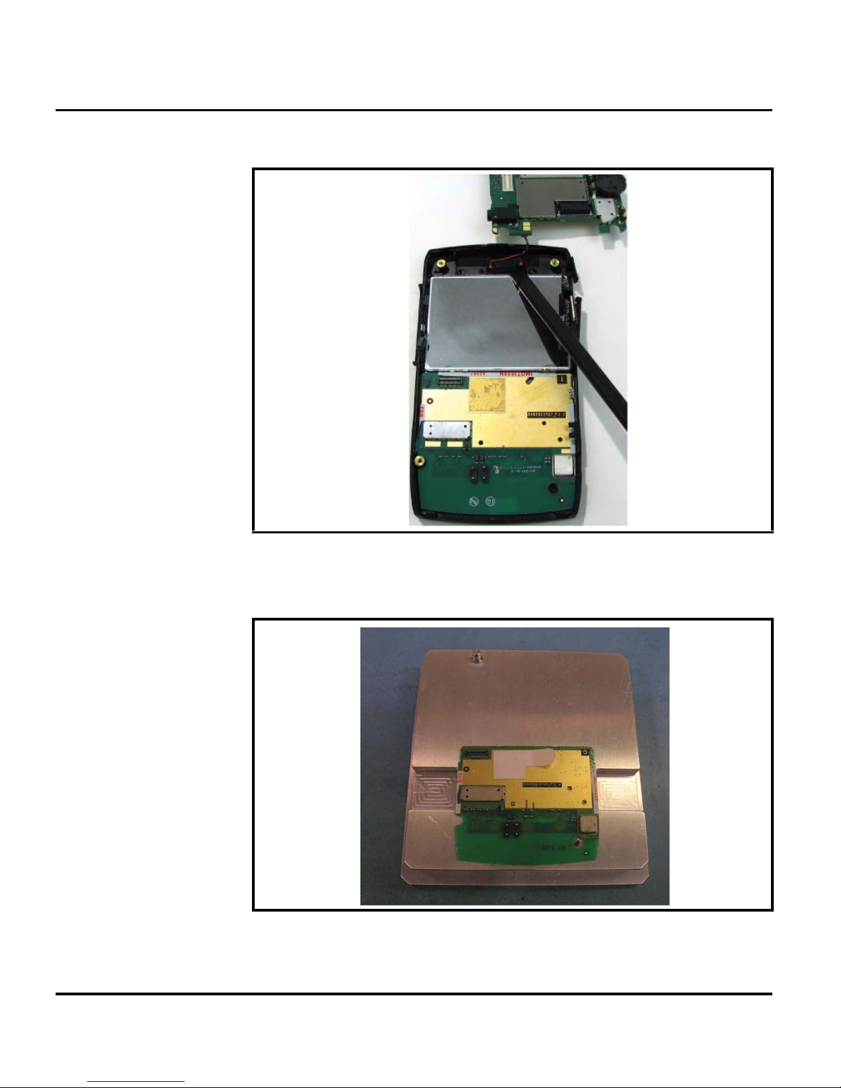
Figure 20. Removing the Main board and Disconnecting the Ear Speaker.
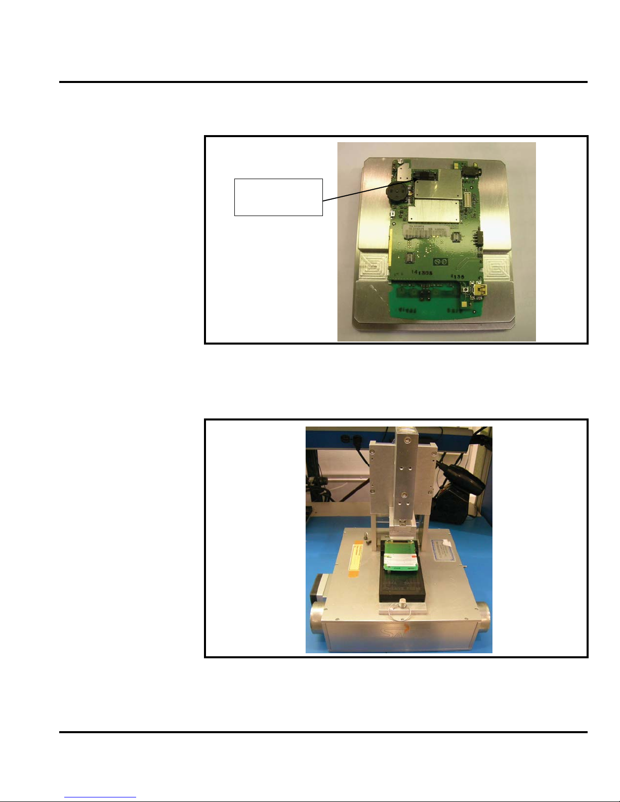
5. To replace, place keyboard on fixture # 2341A as shown.
Figure 21. Removing the Display Connector Pad
061469o
061469o
26 March 28, 2007 6809511A67-O
Page 31
Level 1 and 2 Service Manual Disassembly
6. Remove Liner from doubled sided adhesive on keyboard. Attach keyboard to main board
as shown. Insure that the board to board connector is fully engaged.
Remove Tape
from Connector.
061469o
Figure 22. Removing the Display Connector Pad
7. Activate double side adhesive using Fixture# 2454 and air press set 6 psi and cycle time
to achieve 5 sec dwell of full contact.
Figure 23. Removing the Display Connector Pad
8. Replace the rear housing, SIM, battery, and battery cover as described in the procedures.
6809511A67-O March 28, 2007 27
061469o
Page 32
Disassembly
Removing and Replacing the Antenna
1. Remove the battery cover, battery, SIM, memory card, rear housing and transceiver board
assembly as described in the procedures.
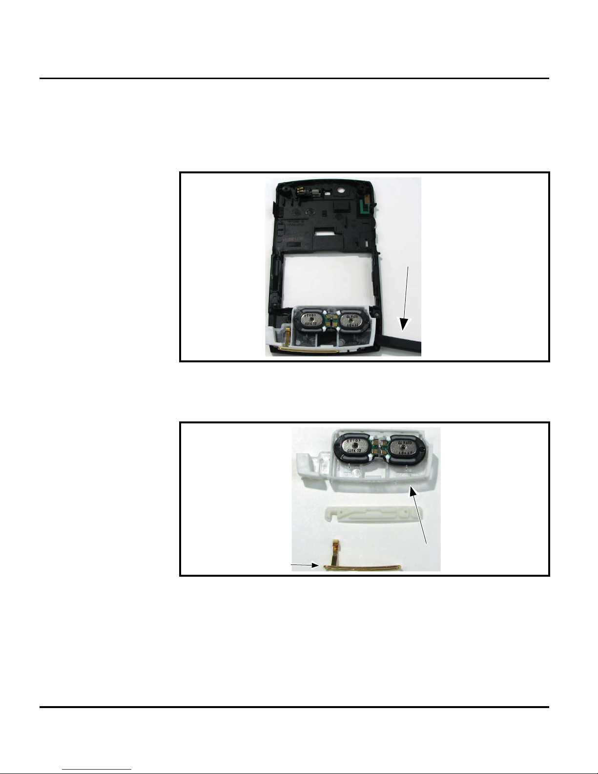
2. Use the plastic tweezers to grasp the plastic antenna and carefully release the bottom
latches, See Figure 24.
Disassembly tool
061467o
Figure 24. Removing the Antenna
3. Use the disassembly tool to separate the antenna assembly, See Figure 25.
Antenna holder
Antenna
assembly
061428o
Figure 25. Separating the Antenna Assembly
4. To replace, assembly starts from right to left. Align the antenna assembly to the phone.
5. Carefully press the antenna assembly into position until the antenna assembly latches snap
into position.
6. Replace the transceiver board, rear housing assembly, SIM, battery and battery cover as
described in the procedures.
28 March 28, 2007 6809511A67-O
Page 33
Level 1 and 2 Service Manual Disassembly
Removing and Replacing the Display Module Assembly
1. Remove the battery cover, battery, SIM, rear housing, transceiver board assembly, and
camera assembly as described in the procedures.
The flexible printed cable (FPC) (flex) is easily damaged. Exercise extreme care when
G
handling.
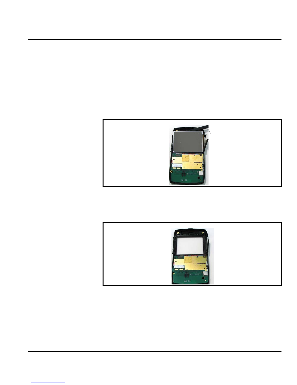
2. Using the disassembly tool, carefully disengage the side hooks of the display bracket.
3. Lift the display from the bracket.
Disassembly tool
Figure 26. Removing the Display Module
4. Carefully and gently lift one corner of the display module assembly out of the housing
assembly.
Figure 27. Display Module Removed
5. To replace the main display lens, properly align the display lens on the bracket.
6. Align the display module to the housing assembly.
6809511A67-O March 28, 2007 29
Page 34
Disassembly
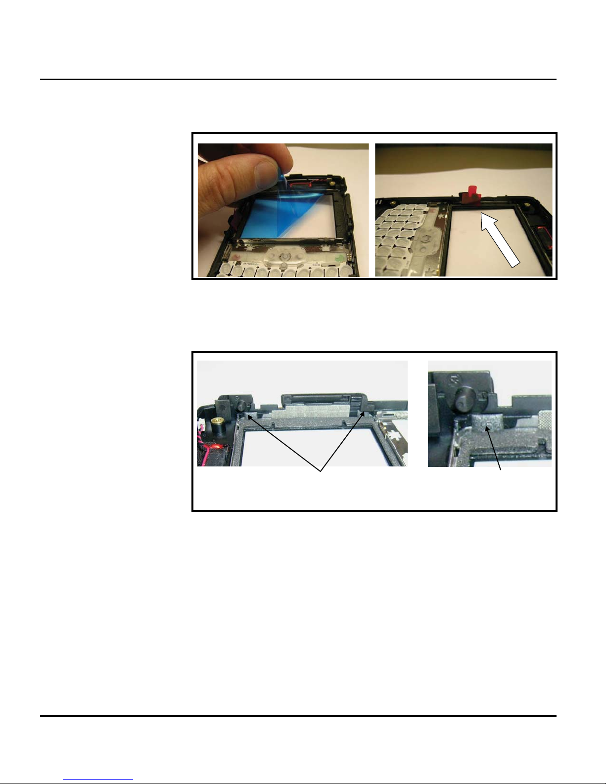
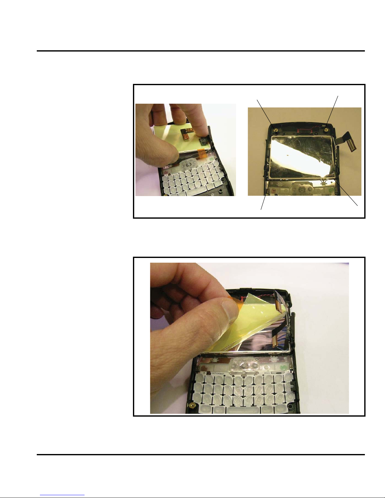
7. Remove protective liners as shown. Remove FM from display and housing using
de-ionized air.
Figure 28. Removing the Protective Liners
8. Gently fold flex upward and place display in place as shown. To prevent display cracking,
engage snaps in order shown below. Only press on edges of display.
These tabs must remain in this
Close up of tab
position. Be careful not to trap tabs
under the LCD display
Figure 29. DisplayPlacement and Tabs
30 March 28, 2007 6809511A67-O
Page 35
Level 1 and 2 Service Manual Disassembly
9. Only fold the display flex in the direction shown. Never bend the flex in the opposite
direction. Bending in the opposite direction will damage the display.
Figure 30. Inserting the Display Module
10. Remove protective liner as shown.
1
4
2
3
6809511A67-O March 28, 2007 31
Figure 31. Removing the Protective Liner
Page 36
Subscriber Identity Module (SIM) and Identification
Subscriber Identity Module (SIM) and Identification
SIM
A SIM is required to access the existing local GSM network, or remote networks when traveling
(if a roaming agreement has been made with the provider).
The SIM contains:
• All the data necessary to access GSM services.
• The ability to store user information such as phone numbers.
• All information required by the network provider to provide access to the network.
Personality Transfer
A personality transfer is required when a phone is express exchanged or when the main board
is replaced. Personality transfers reproduce the customer's original personalized details such as
menu and stored memory such as phone books, or even just program a unit with basic user
information such as language selection. Q telephones use TrueSync® synchronization software
to effect a personality transfer.
Identification
Each Motorola GSM device is labeled with a variety of identifying numbers. The following
information describes the current identifying labels.
Mechanical Serial Number (MSN)
The Mechanical Serial Number (MSN) is an individual unit identity number and remains with
the unit throughout the life of the unit.
The MSN can be used to log and track a unit on Motorola's Service Center Database.
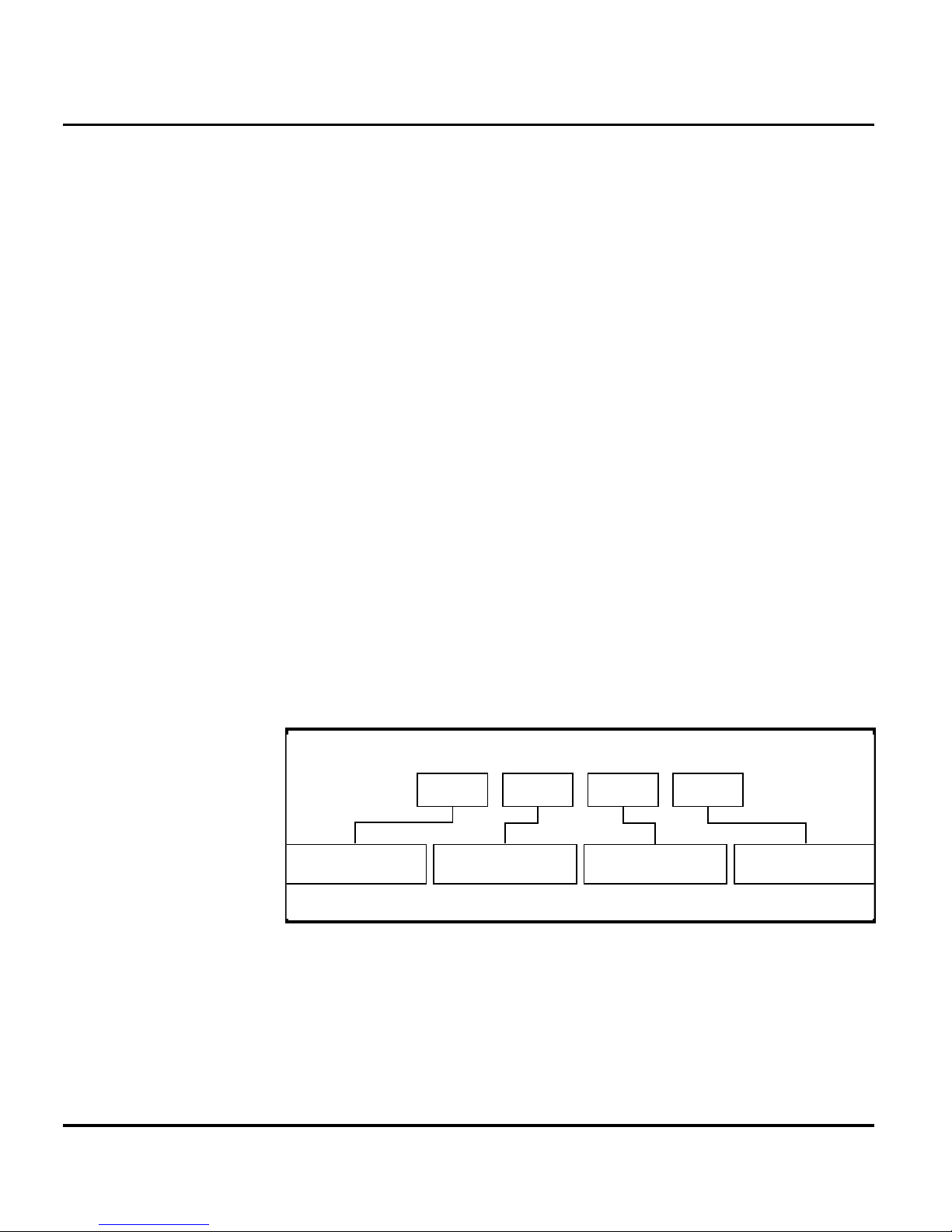
The MSN is divided into 4 sections, as shown in Figure 32.
3 Digits 1 Digit 2 Digits 4 Digits
APC DC DC SNR
Account Product Code
i.e. StarTAC Phone130
TM
Figure 32. MSN Label Breakdown
Distribution Center
i.e. Easter Inch
Date Code: Year and
Month of Shipment
Unit's individual serial
number
000807a
32 March 28, 2007 6809511A67-O
Page 37

Level 1 and 2 Service Manual Subscriber Identity Module (SIM) and Identification
International Mobile Station Equipment Identity (IMEI)
The International Mobile station Eq uipment Identity (IMEI) number is an
individual number unique to the PCB and is stored within the unit's memory.
The IMEI uniquely identifies an individual mobile station and thereby provides a means for
controlling access to GSM networks based on mobile station types or individual units. The full
IMEI structure is listed in Table 2.
Table 2. IMEI Number Breakdown
TAC Serial Number Check Digit
NNXXXXXX ZZZZZZ A
Where
TAC Type Allocation Code, formerly known as Type Approval Code
NN Reporting body identifier
XXXXXX Type Identifier
ZZZZZZ Individual unit serial number
A Phase 1 = 0.
Phase 2 = check digit defined as a function of all other IMEI digits
Other label number configurations present are:
• TRANSCEIVER NUMBER: Identifies the product type. Normally the SWF number. (i.e.
V100).
• PACKAGE NUMBER: Identifies the equipment type, mode, and language in which the
product is shipped.
6809511A67-O March 28, 2007 33
Page 38
Troubleshooting
Troubleshooting
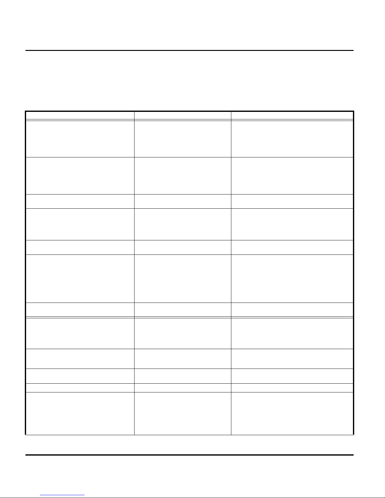
Troubleshooting Chart
Table 3. : Level 1 and 2 Troubleshooting Chart
SYMPTOM PROBABLE CAUSE VERIFICATION AND REMEDY
1. Telephone will not turn on or stay on. a) Battery either discharged or
2. Telephone exhibits poor reception or
erratic operation such as calls frequently
dropping or weak or distorted audio.
3. Display is erratic, or provides partial or
no display.
4. Incoming call alert transducer audio
distorted or volume is too low.
defective.
b) Battery connectors open or
misaligned.
c) Transceiver board assembly
defective.
a) Antenna assembly defective. Check to make sure that the antenna pin is
b) Transceiver board assembly
defective.
a) Transceiver board connections
faulty.
b) Transceiver board assembly
defective.
Faulty transceiver board assembly. Replace the transceiver board assembly (refer
Measure battery voltage across a 50 ohm (>1
Watt) load. If the battery voltage is <3.4 Vdc,
recharge the battery using the appropriate
battery charger. If the battery will not recharge,
replace the battery. If battery is not at fault,
proceed to b.
Visually inspect the battery connectors on both
the battery and the telephone. Realign and, if
necessary, either replace the battery or refer to
a Level 3 Service Center for the battery
connector replacement. If battery connectors
are not at fault, proceed to c.
Forward to an authorized level 3 service center.
properly connected to the transceiver board
assembly. If connected properly, substitute a
known good antenna. If the fault is still present,
proceed to b.
Forward to an authorized level 3 service center.
Remove rear chassis assembly from unit, check
general condition of flexible printed cable (flex).
If the flex is good, check that the flex connector
is fully pressed down. If not, check connector to
transceiver board connections. If faulty
connector, replace the transceiver board
assembly. If connector is not at fault, proceed to
b.
Forward to an authorized level 3 service center.
to 1c). Verify that the fault has been cleared and
reassemble the unit with the new transceiver
board assembly.
5. Telephone transmit audio is weak.
(usually indicated by called parties
complaining of difficulty in hearing voice).
6. Receive audio from earpiece speaker is
weak or distorted.
34 March 28, 2007 6809511A67-O
a) microphone obstructed by user
while holding the phone
b) Microphone defective. Replace the microphone as described in the
c) Transceiver board defective. Forward to an authorized level 3 service center.
a) Connections to or from transceiver
board assembly defective.
Verify transmit audio quality. If transmit audio
quality is still weak and microphone is not
obstructed, proceed to b.
procedures. If fault is not cleared, proceed to c.
Gain access to the transceiver board assembly
as described in the procedures. Check flex and
the flex connector from the front assembly to the
transceiver board assembly. If flex is at fault,
replace front housing assembly. If flex connector
is at fault, proceed to d. If connection is not at
fault, proceed to b.
Page 39
Level 1 and 2 Service Manual Troubleshooting
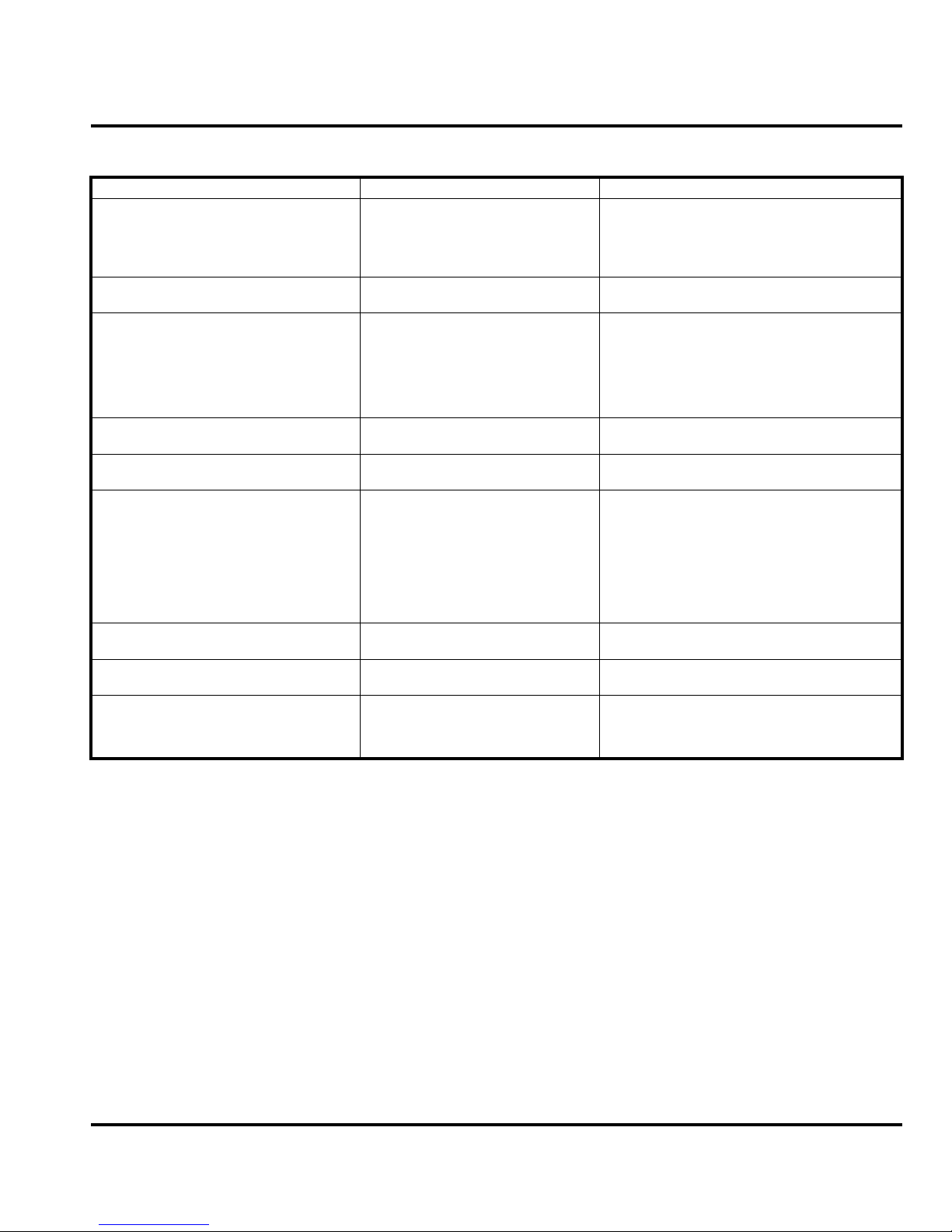
Table 3. : Level 1 and 2 Troubleshooting Chart (Continued)
SYMPTOM PROBABLE CAUSE VERIFICATION AND REMEDY
b) Antenna assembly defective. Check to make sure the antenna is installed
c) Transceiver board assembly
defective.
7. Telephone will not recognize or accept
SIM.
8. Vibrator feature not functioning. Transceiver board assembly defective. Forward to an authorized level 3 service center.
a) SIM defective. Check the SIM contacts for dirt. Clean if
b) Transceiver board assembly
defective.
correctly. If the antenna is installed correctly,
substitute a known good antenna assembly. If
this does not clear the fault, reinstall the original
antenna assembly and proceed to d.
Forward to an authorized level 3 service center.
necessary and check if fault has been cleared. If
the contacts are clean, insert a known good SIM
into the telephone. Power up the unit and
confirm that the SIM has been accepted. If the
fault no longer exists, replace the defective SIM.
If the SIM is not at fault, proceed to b.
Forward to an authorized level 3 service center.
9. Internal Charger not working. Faulty charger circuit on transceiver
10. Real Time Clock resetting when
standard battery is removed.
11. No or weak audio when using headset. a) Headset not fully pushed home. Ensure the headset plug is fully seated in the
board assembly.
Lithium button cell in the display board
may be depleted.
b) Faulty jack socket on transceiver
board assembly.
Test a selection of batteries in the rear pocket of
the desktop charger. Check LED display for the
charging indications. If these are charging
properly, then the internal charger is at fault.
Replace the transceiver board assembly (refer
to 1c). Verify that the fault has been cleared and
reassemble the unit with the new transceiver
board assembly.
Refer service to a Level 3 service center for
replacement.
jack socket. If fault not cleared, proceed to b.
Replace the transceiver board assembly (refer
to 1c). Verify that the fault has been cleared and
reassemble the unit with the new transceiver
board assembly.
Programming: Software Upgrade and Flexing
Contact your local technical support engineer for information about equipment and procedures
for flashing and flexing.
6809511A67-O March 28, 2007 35
Page 40
Troubleshooting
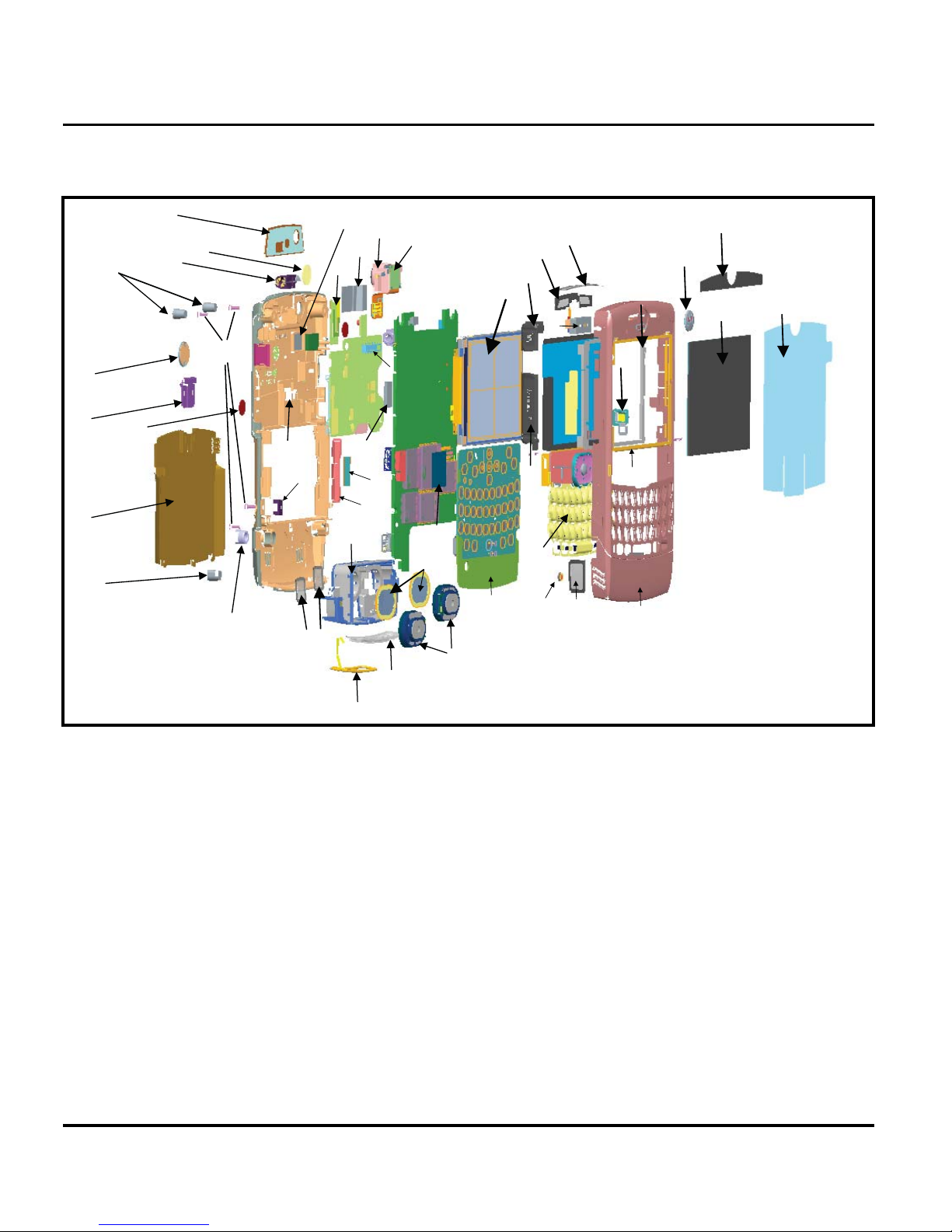
Exploded View Diagram (Main assembly)
14
27
25
32
30
26
17
20
16
29
31
13
41
28a
40
15
36
44
7
42
21
19
28b
33
39
34
43
39
23
35
22
38
6
18
11
4
3
47
45
5
48
46
499
1
10
8
2
12
24
031826o
Figure 33. Exploded View Diagram (Main assembly)
36 March 28, 2007 6809511A67-O
Page 41
Level 1 and 2 Service Manual Troubleshooting
Exploded View Parts List (Main assembly)
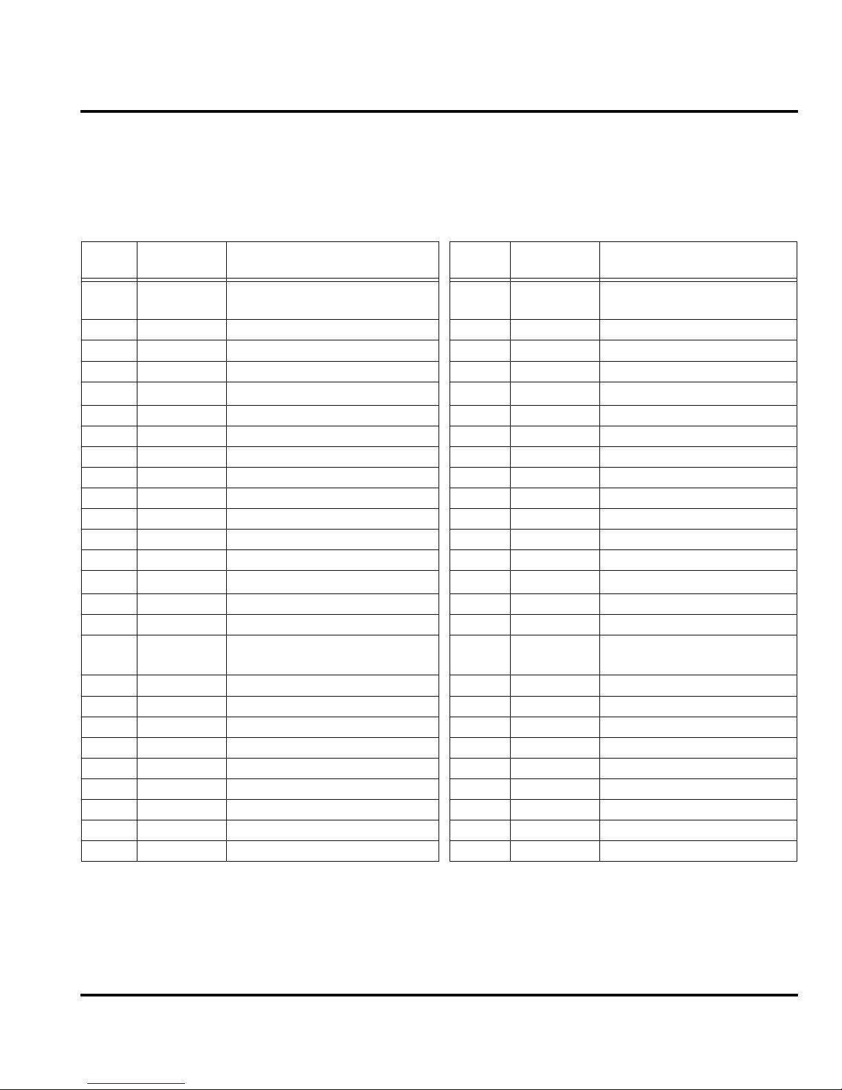
The following part number table is provided only for reference. Please contact your local
Motorola parts organization for current part number information .
Table 4. Exploded View Parts List
Item
Number
Part Number Description Item
Number
1 1571446B01 Front Housing painted, Licorice Black 25 1571206C01 Battery door standard, painted
2 6171110B02 Main Lens 26 4171793B01 Battery door latch spring
3 3571236B01 Screen, earpiece secondary 27 5571196C02 Battery door latch, plated black
4 3571452B01 Screen, earpiece tertiary 28 8471427B01 Camera Module - 1.3 (a)
5 3871041B02 Side Button 0571124B01 Camera Grommet (b)
6 0571119B01 HSJ Grommet 29 0387790L13 Screws (4X)
7 0771117B01 Locking Bracket 30 3871116B01 Screw hole plug, top (2X)
8 1371115B02 Batwing Front 31 3871 301B01 RF grommet
9 3571294C01 Screen, MIC 32 3871127B01 Screw hole plu g, bottom
10 6471043B02 Decorative Bezel 33 7289804Y01 D isplay - Inner Module
11 3871040B07 Keypad Assembly 34 N/A Main Board Assembly
12 1171571C01 Front Liner 35 N/A Keyboard Assembly
13 1571447B01 Rear Housing painted, Licorice Black 36 N/A Daughter Board Assembly
14 1371107B02 Batwing Rear
15 8589419Y01 Bluetooth Antenna 38 4371477B01 Antenna Spacer
16 6187835N02 Lens, Camera 39 3271044F01 Main-Keypad Adhesive
17 6171280B01 Camera Bezel 40 3271840F01 Conductive Gasket, Camera
18 0571058D01 Mini SD Grommet 41 7571282B01 Camera Connector Pad
19 3571419B01 Screen, Rear port 42 5571041F01 Battery Latch
20 0171267C01 Vibrator Motor Assembly 43 7571065F01 Battery Latch Pad
21 1571126B01 Antenna/Speaker Carrier 44 3271827B01 Display Connector Pad
22 5088317Y01 Loud Speaker - 14 x 20 (2x) 45 5071324E01 Earpiece Speaker
23 3571269B01 Screen, Loudspeaker (2x) 46 4271831B01 Ground Clips, Display (2x)
24 8571026B01 Main Antenna 47 3289157Y01 Gasket, Main 2.4 Display
48 3271378D01 Gasket, Display Side
49 3571485B01 Sideport Screen
Part Number Description
black
Connector to BT Shield
There is a danger of explosion if the Lithium Ion battery pack is replaced incorrectly.
Replace only with the same type of battery or equivalent as recommended by the
E
6809511A67-O March 28, 2007 37
battery manufacturer. Dispose of used batteries according to the manufacturer’s
instructions.
Page 42
Troubleshooting
Accessories (Optional)
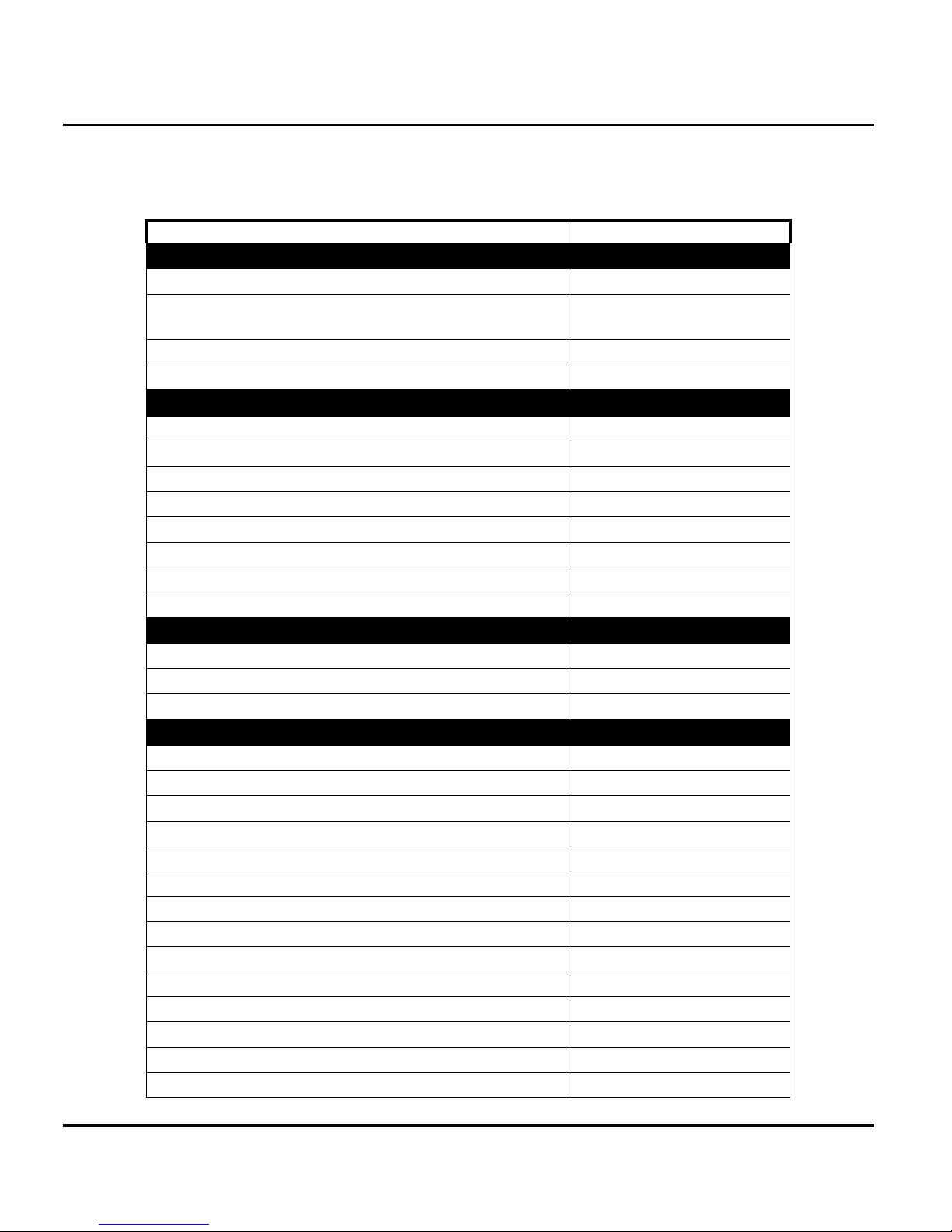
Table 5. Accessories
Part Description Part Number
Automotive & Navigation
Bluetooth Car Kit - High Tier, T505 SYN1717
T305 Portable Bluetooth Hands-Free Speaker, Bluetooth Car
Kit, Mid Tier
T605 Pro Install Bluetooth Carkit SYN1782
BT Pro-Install CarkIt IHF1000r 98676K
Data & Business Communications
Bluetooth Class 1 USB Adapter PC850 SYN1244
128MB microSD card & Mot SD adapter SYN1403
1GB microSD card & Mot SD adapter SYN1406
256MB microSD card & Mot SD adapter SYN1404
2GB microSD card & Mot SD adapter SYN1407
512MB microSD card & Mot SD adapter SYN1405
Grey EMU data cable SKN6234
USB 2.0 SD Card Reader SYN1045
Digital Accessories
Data Cable Mini USB/USB/Serial SKN6371
Data Cable USB/charging AAKN4013
Motorola Phone Tools Phase 4 SVN5539
MobileVoice (Wireless BT Headsets)
SYN1716
Bluetooth Headset H670 Black Slate (Canary) SYN1853
Bluetooth Headset H670 Cosmic Blue (Canary) SYN1855
Bluetooth Headset H670 Silver Quartz (Canary) SYN1852
Bluetooth Headset H550 Silver (SLVR) SYN1822
Bluetooth Headset - Plum - H700 SYN1818
Bluetooth Headset - Dark Pearl Blue - H800 SYN1639
Bluetooth Headset - Fire Red - H700 SYN1820
Bluetooth Headset - MiniBlue H9 SJ0095A
Bluetooth Headset H555 Black/Black (RAZR) SYN1854
Bluetooth Headset - Pale Lilac - H350 SYN1948
Bluetooth Headset - Project (RED) - H500 SYN1966
Bluetooth Headset H505 EZ Pair - Black Gloss SYN1949
Bluetooth Headset H505 EZ Pair - Pink SYN1965
Bluetooth Headset H555 Silver/Black (RAZR) SYN1821
38 March 28, 2007 6809511A67-O
Page 43
Level 1 and 2 Service Manual Troubleshooting
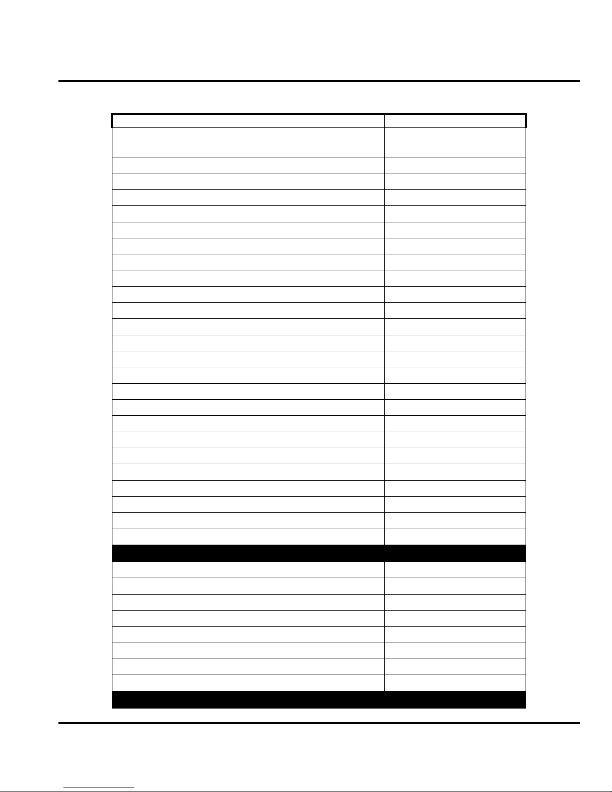
Table 5. Accessories(Continued)
Part Description Part Number
Bluetooth Headset Black H700 (not available in North Amer-
SYN1509
ica)
Bluetooth Headset H700 Blue/Black Cingular Only SYN1508
Bluetooth Mono Headset, Nickel- H500 SYN1290
Bluetooth Headset - H700 (silver) SYN1311
Bluetooth Headset - H605 SYN1303
Bluetooth Headset (Pearl Dark Gray) - H300 SYN1297
Bluetooth Headset H500 Pink SYN1436
Bluetooth Headset H350 Dark Pearl Grey SYN1763
Bluetooth Headset - HS850 (Refresh - Black) SYN1107
Bluetooth Headset - HS850 (Refresh - Blue) SYN1226
Bluetooth Headset (Pink) - H300 SYN1417
Bluetooth Headset (Pure White) - H300 SYN1416
Bluetooth Headset H700 D&G Gold SYN1769
Bluetooth Headset H350 Sapphire Blue SYN1738
Bluetooth Headset H350 Silver Quartz SYN1765
Bluetooth Headset H350 Silver Sail SYN1764
Bluetooth Headset H350 Black SYN1439
Bluetooth Headset Softtouch Black H500 SYN1374
Bluetooth Headset H500 Celery SYN1732
Bluetooth Headset H500 Cosmic Blue SYN1617
Bluetooth Headset H500 Fire Red SYN1667
Bluetooth Headset H500 Hot Pink SYN1525
Bluetooth Headset H500 Oi Branded SYN1735
Bluetooth Headset H500 Pumpkin SYN1733
Bluetooth Headset H500 Steel Teal SYN1734
Modules & Emerging Technologies
Oakley RAZRWIRE (Mercury: NA) - H7 98679H
Oakley RAZRWIRE (Pewter/Black: NA) - H7 98677H
Oakley RAZRWIRE (Plantinum/Rootbeer: NA) - H7 98678H
Reverb (Oakley Stereo Bluetooth Eyewear - BLK) SYN1552
Reverb (Oakley Stereo Bluetooth Eyewear - WHT) SYN1553
REVERB (Oakley Stereo Bluetooth Eyewear Br. Sm.) SYN1554
Audex Motorola Jacket Series Electronics - Deep Spruce SYN1712
Audex Motorola Jacket Series Electronics - Fire Red SYN1713
Music & Entertainment
6809511A67-O March 28, 2007 39
Page 44
Troubleshooting
Table 5. Accessories(Continued)
Part Description Part Number
HT820 BT Stereo Headphones Black (soft-touch black) SYN1967
D&G Stereo Headset SYN1744
EMU STEREO HEADSET FIRE RED S YN1632
JBL Black On Tour Portable Speaker SYN1451
Motorola Bluetooth Active Headphones S9 SYN1902
S200 EMU Stereo HS - Cherry Red SYN1709
S200 EMU Stereo HS - Cingular SYN1562
S255 EMU Mono HS SYN1471
S262 EMU Stereo HS SYN1457
Stereo Headset - EMU SYN1301
Adapter EMU to 2.5mm stereo SYN1505
Adapter EMU to 3.5 mm SYN1504
Bluetooth Stere o Headset & Controller S705 SYN1711
Bluetooth Stereo Headset HT820 SYN0948
S805 DJ Headset - Bluetooth - Music and Telephony SYN1673
JBL On Tour Mobile European Kit OnTourMBBLKE
JBL On Tour Mobile portable speaker US Kit OnTourMBBLK
JBL On Tour Mobile speaker PRC kit CH1414A
JBL On Tour Mobile speaker UK kit OnTourMBBLKU
Sinead Music Dock S850 SYN1847
Power
Vehicle Power Adapter EMU - VC700 SYN0847
Battery BT50 (PF4 Ltd) Li-Ion 880 mAh SNN5771
Standard Car Charger EMU - P310 SYN1630
Charger Adapter EMU/EMU (Y-cable) SKN6222
Travel Charger EMU Mid-Rate Switcher - Argentina SPN5192
Travel Charger EMU Mid-Rate Switcher - Australia SPN5193
Travel Charger EMU Mid-Rate Switcher - BRAZIL SPN5187
Travel Charger EMU Mid-Rate Switcher - EURO SPN5189
Travel Charger EMU Mid-Rate Switcher - INDIA SPN5194
Travel Charger EMU Mid-Rate Switcher - JAPAN SPN5274
Travel Charger EMU Mid-Rate Switcher - KOREA SPN5351
Travel Charger EMU Mid-Rate Switcher - MEXICO SPN5186
Travel Charger EMU Mid-Rate Switcher - PRC SPN5188
Travel Charger EMU Mid-Rate Switcher - TWN SPN5216
Travel Charger EMU Mid-Rate Switcher - UK/HK SPN5190
40 March 28, 2007 6809511A67-O
Page 45

Level 1 and 2 Service Manual Troubleshooting
Table 5. Accessories(Continued)
Part Description Part Number
Travel Charger EMU Mid-Rate Switcher - US ENG SPN5185
Travel Charger EMU Rapid Switcher - Argentina SPN5197
Travel Charger EMU Rapid Switcher - BRAZIL SPN5196
Travel Charger EMU Rapid Switcher - HK SPN5199
Travel Charger EMU Rapid Switcher - Japan SPN5275
Travel Charger EMU Rapid Switcher - MEXICO SPN5200
Travel Charger EMU Rapid Switcher - PRC SPN5198
Travel Charger EMU Rapid Switcher - US SPN5202
Travel Charger EMU Rapid TWN SPN5270
VPA EMU High Performance "Loop" SPN5401
P320 desktop BOC (battery-only-charge), platform, EMU SPN5394
P790 Portable Charger SPN5353
Charger Adapter - Aust/NZ Plug SYN8127
6809511A67-O March 28, 2007 41
Page 46

1 and 2
6809511A67-O
Level 1 and 2 Service Manual Index
Q GSM
Index
A
active line indicator 12
airplane mode indicator
antenna, removing and replacing
B
battery
charge indicator
function
removing
battery housing
removing
battery indicator
Bluetooth indicator
13
15
15
12
C
call forward indicator 12
caller ID
camera assembly, removing and replacing
Canadian Interference-Causing Equipment regulations
changes
conventions
copyrights
8
product
1
3
computer software
D
disassembly 15
display module assembly, removing and replacing
E
exploded view diagram 36
exploded view parts list
F
FCC rules 1
features
caller ID
SIM Toolkit
text entry
Wireless Access Protocol (WAP)
8
8
8
G
GPRS indicator 11
11
28
13
12
21
1
29
37
8
I
identification 32
international mobile station equipment identity
mechanical serial number
product
IM indicators
IMEI
33
in-call indicator
1
12
12
L
LCD 12
liquid crystal display (LCD)
Low Battery message
M
message indicator 12
MSN
32
N
names
product
1
1
O
operation 10
battery
controls, indicators, and I/O connectors
LCD
menu navigation
13
12
P
part numbers
accessories
parts
exploded view diagram
exploded view parts list
product
changes
identification
names
product overview
features
profile indicator
1
1
7
R
rear housing
removing
regulatory agency compliance
18
33
32
12
12
10
12
38
36
37
1
7
12
1
6809511A67-O March 28, 2007 42
Page 47

Level 1 and 2 Service Manual Index
removing
antenna
battery
battery housing
camera assembly
display module assembly cover
rear housing
SIM
transceiver board assembly
replacement parts
contact information
replacing
antenna
battery
camera assembly
display module assembly
rear housing
SIM
transceiver board assembly
28
13, 15
15
21
18
17
4
28
15
21
18
17
S
serial number
mechanical
service manual
about
revisions
scope
service policy
customer support
out of box failure
product support
service procedure
ordering replacement parts
shut down
upon battery removal
signal strength indicator
SIM card
personality transfer
replacing
SIM Toolkit
SIM, removing and replacing
specifications
support
customer
product
32
2
3
2
3
3
3
3
13
11
32
32
17
8
5
3
3
29
17
25
25
4
29
troubleshooting
34
W
WAP (Wireless Access Protocol) 8
warranty service
3
T
text entry 8
tools and test equipment
transceiver board assembly, removing and replacing
6809511A67-O October 12, 2006 43
14
25
Page 48

Page 49

 Loading...