

Page 1
™
PM400
Commercial Series
Two-Way Radio User Guide
Manuel de l'utilisateur
de la radio bidirectionnelle
Page 2

COMPUTER SOFTWARE COPYRIGHTS
The Motorola products described in this
manual may include copyrighted Motorola
computer programs stored in semiconductor
memories or other media. Laws in the United
States and other countries preserve for
Motorola certain exclusive rights for
copyrighted computer programs including, but
not limited to, the exclusive right to copy or
reproduce in any form the copyrighted
computer program. Accordingly, any
copyrighted Motorola computer programs
contained in the Motorola products described
in this manual may not be copied, reproduced,
modified, reverse-engineered, or distributed in
any manner without the express written
permission of Motorola. Furthermore, the
purchase of Motorola products shall not be
deemed to grant either directly or by
implication, estoppel, or otherwise, any license
under the copyrights, patents or patent
applications of Motorola, except for the normal
non-exclusive license to use that arises by
operation of law in the sale of a product.
Page 3

CONTENTS
Computer Software Copyrights . . . inside cover
Safety . . . . . . . . . . . . . . . . . . . . . . . . . . . . . . 5
Product Safety and RF Exposure
Compliance . . . . . . . . . . . . . . . . . . . . . . . . . 5
Introduction . . . . . . . . . . . . . . . . . . . . . . . . . 7
Conventional Radio Systems . . . . . . . . . . . . 7
Trunked Radio Systems . . . . . . . . . . . . . . . . 7
LTR Trunked Systems . . . . . . . . . . . . . . . 7
PM400 Radio Features . . . . . . . . . . . . . . . . . 8
Radio-Wide Features . . . . . . . . . . . . . . . . 8
LTR Trunked Features . . . . . . . . . . . . . . . 8
Conventional Signaling Features . . . . . . . 8
Radio Overview . . . . . . . . . . . . . . . . . . . . . 11
LED Indicators. . . . . . . . . . . . . . . . . . . . . . . 12
Display . . . . . . . . . . . . . . . . . . . . . . . . . . . . 12
Optional Enhanced Keypad Microphone
(RMN5029) . . . . . . . . . . . . . . . . . . . . . . . . 13
Indicator Tones . . . . . . . . . . . . . . . . . . . . . . 15
Programmable Buttons . . . . . . . . . . . . . . . . 16
Menu Buttons . . . . . . . . . . . . . . . . . . . . . . . 19
Menu Button. . . . . . . . . . . . . . . . . . . . . . 19
Menu Scroll Buttons . . . . . . . . . . . . . . . . 19
Navigate the Menu . . . . . . . . . . . . . . . . . 19
Getting Started . . . . . . . . . . . . . . . . . . . . . .21
Turn the Radio On or Off . . . . . . . . . . . . . . .21
Adjust the Volume . . . . . . . . . . . . . . . . . . . .21
Select an LTR Channel/Talkgroup . . . . . . . .22
Select a Conventional Channel . . . . . . . . . .22
Receive a Conventional or LTR Call. . . . . . .22
Monitor . . . . . . . . . . . . . . . . . . . . . . . . . . . . .23
Silent Monitor. . . . . . . . . . . . . . . . . . . . . .23
Open Squelch Monitor. . . . . . . . . . . . . . .23
Transmit an LTR Call . . . . . . . . . . . . . . . . . . 24
Transmit a Conventional Call . . . . . . . . . . . . 24
Repeater or Talkaround Mode . . . . . . . . . . . 25
Revert Memory Channel (1 & 2) . . . . . . . . . .25
Store Memory Channel (1 & 2) . . . . . . . . . . .25
Home Revert AutoKey (1 & 2) . . . . . . . . . . .26
Set Local or Distance Mode . . . . . . . . . . . . . 26
VOX Operation . . . . . . . . . . . . . . . . . . . . . . .26
Program PL/DPL Codes . . . . . . . . . . . . . . . .27
Radio Calls . . . . . . . . . . . . . . . . . . . . . . . . . 29
Selective Radio Inhibit . . . . . . . . . . . . . . . . .29
Receive a Selective Call
(Conventional Operation Only) . . . . . . . . . . 29
Send a Selective Call
(Conventional Operation Only) . . . . . . . . . . 30
Receive a Call Alert™ Page
(Conventional Operation Only) . . . . . . . . . . 30
CONTENTS
1
English
Page 4

Send a Call Alert Page
(Conventional Operation Only) . . . . . . . . . .31
Repeater Access . . . . . . . . . . . . . . . . . . . . .31
Radio Check . . . . . . . . . . . . . . . . . . . . . . . . .32
Emergency Alerts . . . . . . . . . . . . . . . . . . . . .32
Send an Emergency Alert. . . . . . . . . . . . . . . 32
CONTENTS
Clear an Emergency Alert. . . . . . . . . . . . . . . 32
Scan . . . . . . . . . . . . . . . . . . . . . . . . . . . . . . . 33
Talkback . . . . . . . . . . . . . . . . . . . . . . . . . . . . 33
Start System Scan . . . . . . . . . . . . . . . . . . . . 34
Stop System Scan . . . . . . . . . . . . . . . . . . . . 34
Start Auto Scan . . . . . . . . . . . . . . . . . . . . . .35
Stop Auto Scan. . . . . . . . . . . . . . . . . . . . . . .35
Delete a Nuisance Channel/Talkgroup. . . . .35
Restore Channels/Talkgroups to the
Scan List. . . . . . . . . . . . . . . . . . . . . . . .36
Edit a Scan List. . . . . . . . . . . . . . . . . . . . . . . 36
Add or Delete Channels/Talkgroups in a
Scan List. . . . . . . . . . . . . . . . . . . . . . . . . . . 37
Prioritize a Channel/Talkgroup in a Scan
List . . . . . . . . . . . . . . . . . . . . . . . . . . . . . . . 38
Phone. . . . . . . . . . . . . . . . . . . . . . . . . . . . . .41
Receive a Phone Call . . . . . . . . . . . . . . . . . .41
Make a Phone Call . . . . . . . . . . . . . . . . . . . .43
Edit the Phone List . . . . . . . . . . . . . . . . . . . .44
Add an Entry . . . . . . . . . . . . . . . . . . . . . . 45
Delete an Entry . . . . . . . . . . . . . . . . . . . . 45
Edit an Entry . . . . . . . . . . . . . . . . . . . . . . 46
Edit Access/Deaccess Codes . . . . . . . . . 47
Tone Preferences . . . . . . . . . . . . . . . . . . . . 49
Tones On/Off . . . . . . . . . . . . . . . . . . . . . . . . 51
Keypad On/Off Tones . . . . . . . . . . . . . . . . . 51
Call Tone Tagging (Conventional
Operation Only) . . . . . . . . . . . . . . . . . . . . . 52
Escalert (Conventional
Operation Only) . . . . . . . . . . . . . . . . . . . . . 53
User Settings . . . . . . . . . . . . . . . . . . . . . . . 55
Set Squelch Level . . . . . . . . . . . . . . . . . . . . 57
Set Power Level . . . . . . . . . . . . . . . . . . . . . . 57
Option Board On/Off . . . . . . . . . . . . . . . . . . 58
Set the Backlight Intensity . . . . . . . . . . . . . . 59
Display the Software Version . . . . . . . . . . . . 59
Warranty . . . . . . . . . . . . . . . . . . . . . . . . . . . 61
Limited Warranty . . . . . . . . . . . . . . . . . . . . . 61
Accessories . . . . . . . . . . . . . . . . . . . . . . . . 65
Antennas . . . . . . . . . . . . . . . . . . . . . . . . . . . 65
Alarm and Accessories . . . . . . . . . . . . . . . . 65
Audio . . . . . . . . . . . . . . . . . . . . . . . . . . . . . . 65
English
2
Page 5

Cables. . . . . . . . . . . . . . . . . . . . . . . . . . . . . 66
Control Station . . . . . . . . . . . . . . . . . . . . . . 66
Data - CES Wireless Technologies. . . . . . . 66
Mounting . . . . . . . . . . . . . . . . . . . . . . . . . . . 67
Public Address . . . . . . . . . . . . . . . . . . . . . . 67
CONTENTS
3
English
Page 6

Notes:
CONTENTS
English
4
Page 7

SAFETY
!
PRODUCT SAFETY AND RF EXPOSURE COMPLIANCE
Before using this product, read
the operating instructions for safe
usage contained in the Product
C a u t i o n
Safety and RF Exposure booklet
enclosed with your radio.
ATTENTION!
This radio is restricted to occupational use
only to satisfy FCC RF energy exposure
requirements. Before using this product, read
the RF energy awareness information and
operating instructions in the Product Safety
and RF Exposure booklet enclosed with your
radio (Motorola Publication part number
68P81095C99) to ensure compliance with RF
energy exposure limits.
For a list of Motorola-approved antennas,
batteries, and other accessories, visit the
following web site which lists approved
accessories: http://www.motorola.com/cgiss/
index.shtml.
5
English
SAFETY
Page 8

SAFETY
Notes:
English
6
Page 9

INTRODUCTION
Your PM400™ radio can operate on both LTR®
trunked and conventional radio systems. This
radio combines the very latest in two-way
technology while delivering outstanding
functionality at the touch of a button.
CONVENTIONAL RADIO SYSTEMS
Conventional typically refers to radio-to-radio
communications through a single channel.
Conventional systems also allow radio users to
extend communication coverage by relaying
their messages through a repeater. To ensure
coordinated use by multiple users, each radio
user must monitor the channel or repeater
before transmitting to verify that the system is
not currently busy.
TRUNKED RADIO SYSTEMS
A trunked radio system allows a large number
of users to share a relatively small number of
frequencies or repeaters without interfering
with each other. The airtime of all the repeaters
in a trunked system is pooled, which
maximizes the amount of airtime available to
any one radio and minimizes channel/
talkgroup congestion.
Some of the benefits of trunked two-way radio
systems are:
• No channel/talkgroup monitoring required prior
to transmission
• Improved system access
• Automatic channel/talkgroup selection
• Increased privacy among members of the same
group
LTR Trunked Systems
LTR (Logic Trunked Radio) is a transmissionbased trunking protocol developed by the E. F.
Johnson Company for primarily single-site
trunking applications. In transmission trunking,
a repeater is used for only the duration of a
single transmission. Once a transmission is
completed, that repeater becomes available to
other users. This means that a conversation
comprised of many transmissions may occur
over several different channels/talkgroups
within the LTR system. This method of trunking
provides system efficiency by making
repeaters available to all users after every
transmission.
When an LTR trunked radio user wants to
communicate with another radio, the user’s
7
INTRODUCTION
English
Page 10

INTRODUCTION
radio sends a “channel/talkgroup request” to
the home repeater. The system then sends
back a “channel/talkgroup grant” to the user’s
radio. The channel/talkgroup grant message
contains the number of a “go to” repeater to tell
the radio which repeater to use. This “go to”
repeater can be the same as the radio’s home
repeater or another repeater in the system.
The radio uses the “go to” repeater for
transmission. Once the transmission has
ended, this repeater is available for other
users.
PM400 RADIO FEATURES
Radio-Wide Features
• 64 Conventional Channels
• Up to 10 Sites and 100 Talkgroups
• Up to 20 Repeaters per Site
• 8-Character Alphanumeric Display
• 4 Programmable Feature Buttons
• 2 Memory Channels
• Telephone Interconnect
• User-programmable Phone, Scan, and TPL/
DPL Lists
• Option Board Expandability
• Busy Channel Lockout
• High/Low Power Settings
• Transmit Time-Out Timer
• Monitor and Sticky Permanent Monitor
• System Scan with 2 Priority Levels and Revert
Scan
• Companding Mode
• Group Data Receive
LTR Trunked Features
• MDC 1200 Signaling
- Selective Radio
Inhibit Decode
- Radio Check
Decode
-MDC Pre-Time
-DOS
- LTR Data Revert
Mode
- Universal ID
Receive
-PTT ID Encode/
Decode
Conventional Signaling Features
• MDC 1200 Signaling
- Emergency Alert
Encode
- PTT ID Encode/
Decode
- Selective Radio
Inhibit Decode
English
8
Page 11

• Quik-Call II Signaling
- Call Alert
Encode/Decode
- Selective Call
Encode/Decode
• DTMF Signaling
- DTMF PTT ID
Encode
- DTMF Call Alert
Encode
- Radio Call List
- Call Tone
Tagging
-DTMF
Selective Call
Encode
INTRODUCTION
9
English
Page 12

Notes:
INTRODUCTION
English
10
Page 13
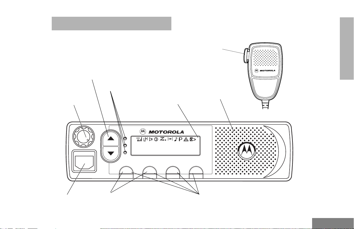
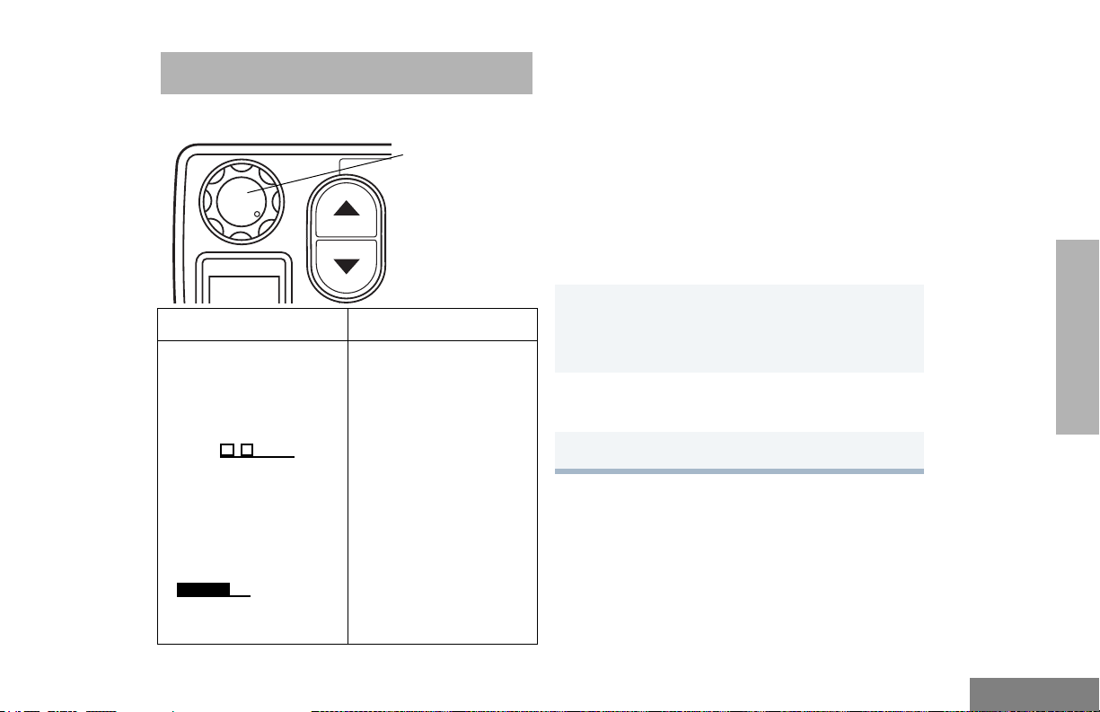
RADIO OVERVIEW
Channel Selector/
Menu Scroll Buttons
Red/Yellow/Green
LED Indicators
On/Off/Volume
Knob
RADIO OVERVIEW
Push-To-Talk
(PTT) Button
Speaker
Display
PERS4
PM400
Microphone
Jack
Menu Buttons
(P1, P2)
P1 P3 P4
P2
Programmable Buttons
(P1, P2, P3, P4)
11
English
Page 14
RADIO OVERVIEW
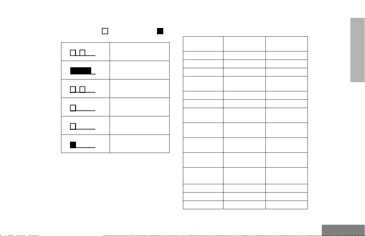
LED INDICATORS
Indicates power up, transmit, receive, scan,
monitor status, channel/talkgroup busy, Call
Alert™ receive/transmit, and Selective Call
receive/transmit.
LED State/Color Indication
Radio Call
Red Transmitting
Flashing Red Receiving
Flashing Red Channel/Talkgroup Busy
Scan
Flashing Green Scanning for activity
Call Alert
Flashing Yellow Indicates receiving a Call Alert
Yellow Indicates sending a Call Alert
Selective Call
Flashing Yellow Indicates receiving a Selective
Call
Yellow Indicates sending a Selective
Call
Sticky Monitor/Open Squelch
Yellow While monitoring
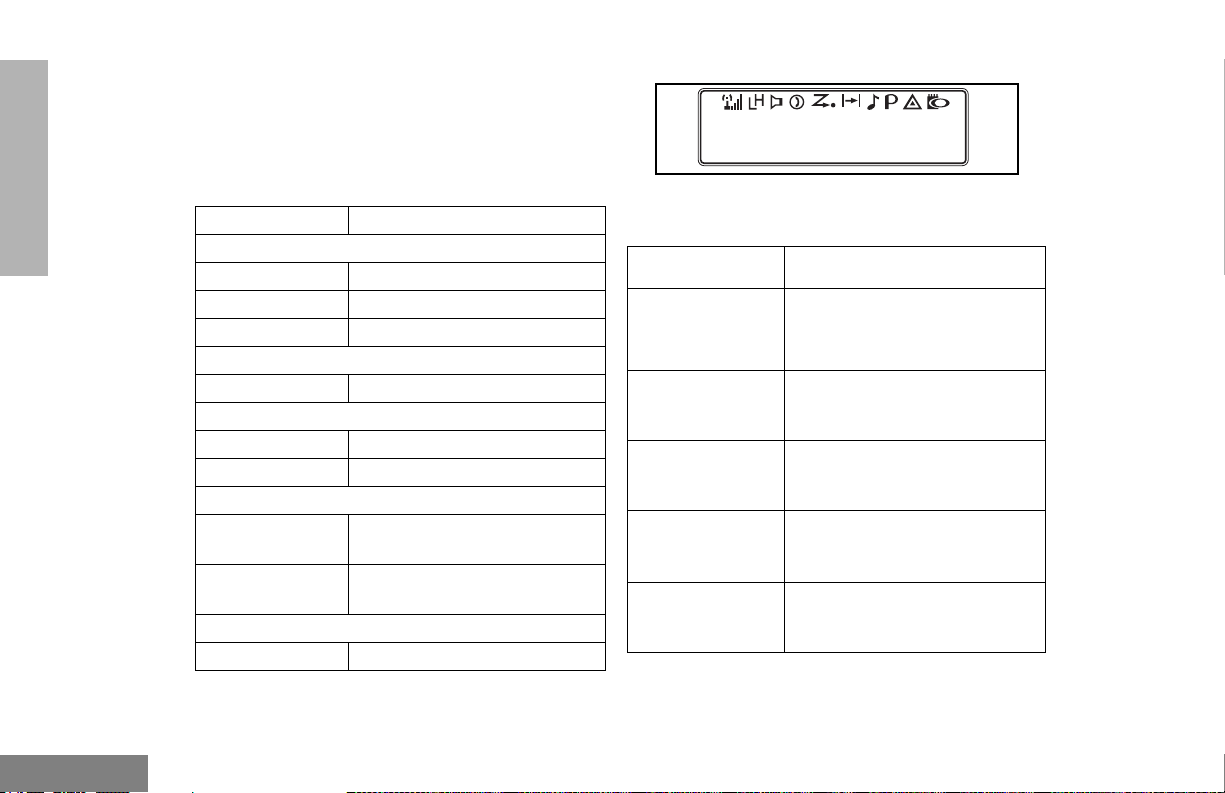
DISPLAY
PERS4
The top row displays menu and radio status
information:
Symbol Indication
I
Signal Strength
B
Power Level
C
Monitor
D
Phone
G
Scan
The more bars, the stronger
the signal being received by
your radio.
Low Power “ R” or High
Power “ S” is activated.
The selected channel is being
monitored.
Phone mode is selected.
Indicates that the Scan
feature has been activated.
English
12
Page 15
Symbol Indication
H
Priority 1 Scan
(
flashing)
•
H
Priority 2 Scan
(
steady)
•
Indicates scan has stopped
and landed on an active
Priority 1 channel/talkgroup.
Indicates scan has stopped
and landed on an active
Priority 2 channel/talkgroup.
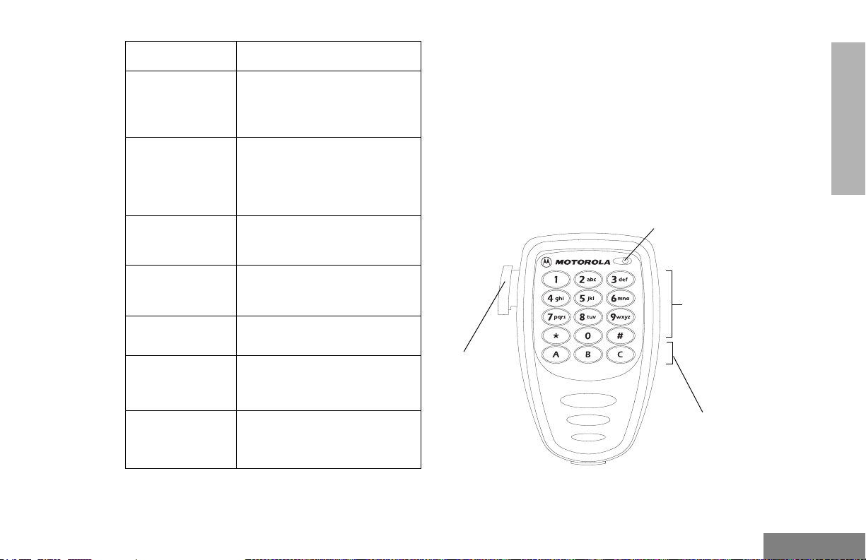
OPTIONAL ENHANCED KEYPAD MICROPHONE (RMN5029)
Your radio may be ordered with an optional
DTMF (Dual-Tone Multi-Frequency)
microphone that has a direct entry keypad.
This keypad microphone has three
programmable buttons (A, B, C) below the
keypad that can be programmed to
conveniently activate select radio features.
RADIO OVERVIEW
J
Talkaround
F
Call Received
B
E
Emergency
A
Option Board
You are not transmitting
through a repeater
A Selective Call or Call Alert
has been received.
Not Used
An Emergency Alarm is being
sent.
An Option Board has been
activated.
Microphone
DTMF
Keypad
Push-to-Talk
(PTT) button
Programmable
Buttons
(A, B, C)
13
English
Page 16

RADIO OVERVIEW
The keypad is used for:
• Dialing a phone number.
• Entering information when programming
phone lists.
• Directly accessing preprogrammed features
(see page 17).
Each key can generate several different
characters. For example, to enter the
character “C,” press the 2 button three
times. (Refer to the Entering Characters
Using the DTMF Microphone Keypad
table.)
Entering Characters Using the DTMF
Microphone Keypad
Number of Times Button is Pressed
Button 1 2 3 4 5
0
1
2
3
4
5
6
0
1/ \
ABC2
DEF3
GH I 4
JKL5
MNO6
English
14
7
8
9
*
#
PQRS7
TUV8
WX YZ 9
*<>
#+ -_
Page 17
INDICATOR TONES
High pitched tone Low pitched tone
Self Test Pass Tone
Se l f Te st F a i l To n e
Positive Indicator Tone
Negative Indicator Tone
Good Key Press
Bad Key Press
Some programmable buttons use tones to
indicate one of two modes:
Programmable
Buttons
Scan Start Stop
Power Level High Low
Squelch Tight Normal
Repeater/
Talkaround
VOX Enabled Disabled
Local/Distance Local Distance
Sticky Monitor/
Open Squelch
Revert Memory
Channel (1&2)
Store Memory
Channel (1&2)
Home Revert
AutoKey (1&2)
Menu Mode
Positive
Indicator Tone
Does not use
repeater
— Enabled
— Enabled
— Stored
— Enabled
— Accessed
Negative
Indicator Tone
Uses repeater
D
Radio Call — Enabled
Scan List Edit — Enabled
Speed Dial — Enabled
RADIO OVERVIEW
15
English
Page 18

RADIO OVERVIEW
Programmable
Buttons
Phone Mode — Enabled
Option Board Enabled Disabled
Escalert Enabled Disabled
Positive
Indicator Tone
Negative
Indicator Tone
PROGRAMMABLE BUTTONS
Your radio has four programmable buttons.
Your dealer/programmer can program these
buttons as shortcuts to various radio features.
Check with your dealer/programmer for a
complete list of functions your radio supports.
Programmable buttons include:
• The four front buttons (
C, D, E, and
F).
• The three buttons (A, B, and C) of the
optional DTMF microphone.
Some buttons can access up to two features,
depending on the type of button press:
• Short Press — quickly pressing and
releasing the programmable buttons,
• Long Press — pressing and holding the
programmable buttons for a
preprogrammed period of time,
or
• Hold Down — pressing and holding down
the programmable buttons while checking
status or making adjustments.
The table on page 17 summarizes the
programmable features available and shows
the page number where the feature is
explained.
In the “Button” column, have your dealer/
programmer record the name of the
programmable button next to the feature that
has been programmed to it.
The dealer/programmer can use the
abbreviations (P1, P2, P3, or P4) shown in the
radio illustration on page 11.
Also, where appropriate, have your dealer/
programmer indicate whether the button press
requires a short press, a long press, or needs
to be held down.
English
or
16
Page 19

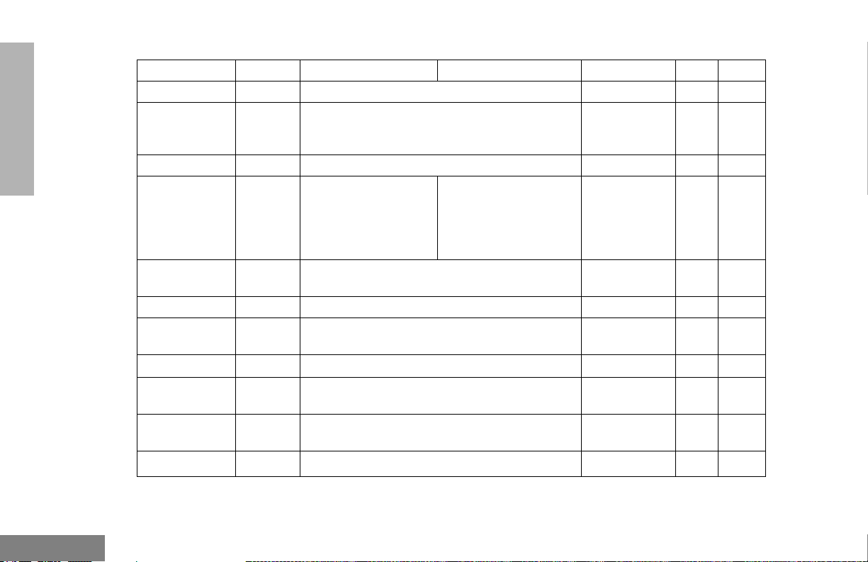
Programmable Features
Function Indicator Short Press Long Press Hold Down Page Button
Menu Mode —
Volume Set — — — Sounds a tone
Monitor
Repeater/
Talkaround
Revert
Memory
Channel (1&2)
Store Memory
Channel (1&2)
Home Revert
AutoKey (1&2)
†
This function is activated by EITHER a short OR a long press, but not both.
J Toggle between using a repeater or transmitting
— Provides direct channel/talkgroup access.
—
D button enters Menu Mode and selects
menu options.
assigned to exit Menu Mode.
Toggle silent monitor
operation (also turn off
C
open squelch monitor
when it has been activated).
directly to another radio.
If a Revert Memory Channel is an LTR talkgroup,
the radio keys-up and transmits an MDC PTT ID.
If a Revert Memory Channel is a conventional
channel, it does not key-up.
C button is automatically re-
†
Turn on open squelch
monitor.
†
— Stores current
channel/talkgroup.
†
†
—19
21
for adjusting
your radio’s
volume level.
—23
—25
—25
—25
—26
RADIO OVERVIEW
D
17
English
Page 20
RADIO OVERVIEW
Programmable Features (Continued)
Function Indicator Short Press Long Press Hold Down Page Button
Local/Distance — Toggle between local mode and distance mode.
Voice Oper-
— Toggle VOX on and off.
†
ated Transmission (VOX)
Radio Call — Directly access the radio call menu.
Scan/
Nuisance
Channel/
G Toggle scan on and off. Delete a nuisance chan-
nel/talkgroup while scanning.
†
Talkgroup
Delete
Edit Scan List
—
Directly access the Scan Edit menu to add,
delete, or prioritize channels/talkgroups.
Phone D Directly access Phone mode.
†
Speed Dial D Directly Access Phone mode to quickly access
†
†
Escalert On/Off
—
phone list for speed dial.
Toggles escalert on and off.
Squelch — Toggles squelch level between tight and normal
squelch.
Power Level
Option Board
†
This function is activated by EITHER a short OR a long press, but not both.
B
A
Toggle transmit power level between High and
Low.
Toggle the option board on and off.
†
†
†
†
—26
—26
— 30,30
— 34,
35
—36
†
— 41,43
—44
—53
—57
—57
—58
English
18
Page 21

MENU BUTTONS
Menu Button
If preprogrammed by your dealer/programmer,
the two front buttons (
used, in conjunction with other programmable
features, to access and select menu options
(
D); and exit menu mode (C).
The
D button can be preprogrammed by
your dealer/programmer to either a short or
long press to access the Menu Mode.
Menu Scroll Buttons
Used to scroll while in Menu Mode.
Refer to the menu navigation chart for
menu selectable features at the back of
this manual.
Navigate the Menu
C and D) can be
G or H to scroll through the menu options. If
you scroll past the last option, the selection
wraps around and starts again.
When you reach the required option, a short
press of the
enters the Sub-menu.
D button selects that option and
G or H to scroll through the sub-menu
options. Select the option with a short press of
the
D button.
Exit the Menu
While in Menu Mode, the
automatically assigned to completely exit the
Menu Mode by a long press or by a series of
short presses to exit from a sub-level of the
menu hierarchy.
The radio also exits the menu mode if there
have been no inputs via the navigation buttons
for the “Inactivity Time” or after a selection has
been made.
Once you have exited Menu Mode, the
and
D buttons return to normal
programmable condition.
C button is
C
RADIO OVERVIEW
19
English
Page 22

RADIO OVERVIEW
Notes:
English
20
Page 23
GETTING STARTED
P
4
TURN THE RADIO ON OR OFF
On/Off/Volume
Control Knob
PERS
ON OFF
Rotate the On/Off/
Volume Control knob
clockwise. If power-up
is successful, you will
hear the Self-Test Pass
Tone ( ) and
see the green LED
indicator and display
icons light momentarily.
If the radio fails to
power up, you will hear
th e S e lf Te s t F a i l To n e
( ). The radio
will need to be returned
for re-programming.
Rotate the On/Off/
Volume Control knob
counterclockwise until
you hear a click and
both the display and
LED indicators turn off.
ADJUST THE VOLUME
Turn the On/Off/Volume Control knob
clockwise to increase the volume, or
counterclockwise to decrease the volume.
– or –
Note: Your dealer/programmer can
preprogram one of the programmable
buttons to Volume Set.
1 Hold down the Volume Set button (see
page 17).
• You will hear a continuous tone.
2 Turn the On/Off/Volume Control knob to
the desired volume level.
3 Release the Volu m e S e t button.
GETTING STARTED
21
English
Page 24

SELECT AN LTR CHANNEL/ TALKGROUP
RECEIVE A CONVENTIONAL OR LTR CALL
GETTING STARTED
Your PM400 radio can be programmed with up
to 10 LTR sites and a maximum of 100
talkgroups, in total, across one or more sites
(up to a total of 10 sites).
To select an LTR Channel/Talkgroup:
G or H to select the appropriate LTR channel/
talkgroup.
SELECT A CONVENTIONAL CHANNEL
Up to a total of 64 channels can be
programmed into your radio.
Select a Channel
G or H to select the desired channel.
1 Turn your radio on.
2 Adjust the radio’s volume, if necessary (see
page 21).
3 G or H to select the desired channel/
talkgroup.
• Make sure the PTT button is released.
4 Listen for voice activity.
• The red LED indicator flashes while your
radio is receiving.
5 To respond, hold the microphone vertically 1
to 2 inches (2.5 to 5 cm) from your mouth.
Press the PTT button to talk; release it to
listen.
English
22
Page 25

MONITOR
It is important to monitor traffic before
transmitting to ensure that you do not “talk
over” someone who is already transmitting.
Silent Monitor
1 A short press of the preprogrammed
Monitor button places the radio in Silent
Monitor mode.
• You hear a high-pitched tone.
2 A short press of the Monitor button cancels
Silent Monitor mode and returns the radio to
normal operation.
Open Squelch Monitor
1 To place the radio in Open Squelch mode,
press and hold the preprogrammed Monitor
button until you hear a high-pitched tone.
• If no activity is present, you will hear
“white noise.”
2 Momentarily press the Monitor button to
return to normal operation.
Note: Depending on how your radio has been
programmed, per channel for transmit
and receive conditions, when the
microphone has been taken off-hook,
the radio will go into Open Squelch
mode.
GETTING STARTED
23
English
Page 26

GETTING STARTED
TRANSMIT AN LTR CALL TRANSMIT A CONVENTIONAL
CALL
G or H to select the appropriate LTR
1
channel/talkgroup.
Hold the microphone in a vertical position at
2
a distance of about 1 to 2 inches
(2.5 to 5 cm) from your mouth.
Press and hold the PTT button.
3
–or–
Press and release the PTT button and wait 3
seconds.
• If access to the trunked system was
successful, the red LED indicator lights
steady.
• If access to the trunked system was
unsuccessful, the red LED indicator
flashes, indicating that the system was
busy or out-of-range.
With the PTT button depressed, speak
4
clearly into the microphone
Release the PTT button to listen.
5
1 Turn your radio on.
2 G or H to select the desired channel.
3 Hold the microphone vertically 1 to 2 inches
(2.5 to 5 cm) from your mouth. Press the
PTT button to talk.
• The red LED indicator lights steady while
the call is being sent.
4 Release the PTT button to listen.
English
24
Page 27

REPEATER OR TALKAROUND J MODE
Talkaround Mode enables you to communicate
with another radio when either:
• The repeater is not operating.
– or –
• Your radio is out of the repeater’s range but
within communicating distance of another
radio.
Note: The J symbol appears on the display
when Talkaround Mode is selected.
Select either Repeater Mode or Talkaround
Mode
Press the preprogrammed Repeater/
Talkaround button (see page 17) to toggle
between Repeater Mode and Talkaround Mode.
– or –
D to enter menu mode.
1
G or H until
2
D to select the current setting.
3
TALKARND
G or H until
4
– or – until
D to select the current setting.
5
TALKARND
REPEATER
REVERT MEMORY CHANNEL (1 & 2)
The Revert Memory Channel feature allows
you to instantly access up to two of your
favorite channels/talkgroups at the touch of a
button.
To Activate Revert Memory Channel
Press the preprogrammed Revert Memory
Channel 1 button or Revert Memory Channel
2 button (see page 17).
STORE MEMORY CHANNEL (1 & 2)
The Store Memory Channel feature allows you
to store a channel/talkgroup for the Revert
Memory Channel feature.
G or H to select the desired channel/
talkgroup. Press the preprogrammed Store
Memory Channel 1 button or Store Memory
Channel 2 button to store that channel/
talkgroup (see page 17).
GETTING STARTED
25
English
Page 28

GETTING STARTED
HOME REVERT AUTOKEY (1 & 2)
If a Revert Memory Channel is an LTR
talkgroup, the Home Revert AutoKey feature
automatically keys-up and transmits an MDC
PTT ID. If a Revert Memory Channel is
programmed as a Conventional channel, the
radio will not key-up (see page 17).
SET LOCAL OR DISTANCE MODE
Use this feature between Local mode (low
sensitivity) and Distance mode (normal
sensitivity). Local mode reduces interference
from other radios in close proximity. Distance
mode improves the radio’s range.
Press the preprogrammed Local/Distance
button (see page 17) to toggle between Local
and Distance mode.
VOX OPERATION
When hands-free operation is desired, your
radio can transmit by voice alone using the
VOX feature when you speak through a voice
activated external microphone that is
connected to your radio.
Note: A voice activated external microphone
must be connected to your radio prior to
power-up of the radio in order to activate
the VOX feature.
To enable or disable VOX operation on a
channel/talkgroup, press the preprogrammed
VOX button (see page 18).
Note: Pressing the PTT button disables VOX.
– or –
You can select channels/talkgroups to enable
or disable VOX as preprogrammed by your
dealer/programmer.
1
G or H to select a channel/talkgroup that
has been preprogrammed to enable VOX.
Note: Pressing the PTT button disables
VOX.
G or H to select a channel/talkgroup that
2
has not been preprogrammed to disable
VOX.
English
26
Page 29

You can select channels/talkgroups to enable
or disable VOX as preprogrammed by your
dealer/programmer.
1
G or H to select a channel/talkgroup that
has been preprogrammed to enable VOX.
Note: Pressing the PTT button disables
VOX.
2 G or H to select a channel/talkgroup that
has not been preprogrammed to disable
VOX.
PROGRAM PL/DPL CODES
G or H until
4
– or – until
D to select the current setting.
5
G or H to scroll through the standard
6
TPL frequencies or DPL codes.
– or –
Enter a non-standard or standard 4-digit
TPL frequency or the 3-digit octal code
(numbers 0-7 only) for DPL via the DTMF
microphone keypad.
D to confirm selection.
7
RX XXX.X
TX XXX.X
GETTING STARTED
Use this feature to edit the Private-Line/Digital
Private-Line codes for a selected channel/
talkgroup.
1 D to enter menu mode.
G or H until
2
D to select
3
EDIT PL
EDIT PL
C until you exit menu mode.
8
27
English
Page 30

GETTING STARTED
Notes:
English
28
Page 31

RADIO CALLS
RECEIVE A SELECTIVE CALL F
(CONVENTIONAL OPERATION ONLY)
SELECTIVE RADIO INHIBIT
Your radio is equipped with a security feature
that can temporarily render the unit inoperative
when an inhibit signal is sent from the base
station.
This feature is commonly used to disable
radios:
• In case of theft
• When your vehicle is being serviced
• For system control reasons
When your radio has been rendered
inoperative by the base station, all controls will
be inoperative except for the On/Off/Volume
knob and the display shows INHIBIT.
When you receive a Selective Call:
• The display shows F and the prepro-
grammed name or ID of the calling radio.
• The yellow LED indicator flashes, if programmed by your dealer/programmer.
• You hear two high-pitched tones.
To acknowledge the call, press and release the
1
PTT button.
Press and hold the PTT button to talk; release
2
to listen.
RADIO CALLS
29
English
Page 32

SEND A SELECTIVE CALL
(CONVENTIONAL OPERATION ONLY)
You can send a Selective Call to a particular
radio or to a group of radios, as programmed
by your dealer/programmer.
Press the preprogrammed Radio Call button
(see page 18), and proceed to step 4.
–
or –
D to enter menu mode
1
Press the PTT button to send the call.
7
Press and hold the PTT button to talk; release
8
to listen.
When the call is completed,
9
C until you exit menu mode.
RECEIVE A CALL ALERT™ PAGE F
(CONVENTIONAL OPERATION ONLY)
RADIO CALLS
English
G or H until
2
D to select
3
G or H until
4
D to select
5
G or H to locate the desired ID in the Call
6
List.
- or -
When using the enhanced keypad microphone, enter a valid DTMF digit to move to
that location in the list.
30
RAD CALL
RAD CALL
SEL CALL
SEL CALL
When you receive a Call Alert page:
• The display shows F and the prepro-
grammed name or ID of the calling radio.
• The yellow LED indicator flashes, if programmed by your dealer/programmer.
• You hear four high-pitched tones.
To acknowledge the page, press and release
the PTT button; to cancel the page, press any
other key.
Page 33

SEND A CALL ALERT PAGE
(CONVENTIONAL OPERATION ONLY)
You can alert another person by sending a Call
Alert page.
Press the preprogrammed Radio Call button
(see page 18) and proceed to step 4.
–
or –
D to enter menu mode
1
G or H until
2
D to select
3
RAD CALL
RAD CALL
When the page is completed,
8
C until you exit menu mode.
REPEATER ACCESS
Use with Enhanced Keypad Microphone
(RMN5029)
Use this feature to send DTMF tones to a
repeater.
1 Press and hold the PTT button and enter
your access code using the DTMF keypad.
2 Press and release the required DTMF but-
tons.
G or H until
4
D to select
5
G or H to locate the desired ID in the Call
6
List.
- or -
When using the enhanced keypad microphone, enter a valid DTMF digit to move to
that location in the list.
Press the PTT button to send the page.
7
CALL ALT
CALL ALT
3 Release the microphone’s PTT button.
RADIO CALLS
31
English
Page 34

RADIO CHECK
Radio Check allows you to determine if a radio
is within the range of the trunked system and
turned on, without disturbing the user of that
radio. This feature can also be used when
attempts with Selective Call and Call Alert fail.
EMERGENCY ALERTS E
Your radio offers choices for initiating and
responding to Emergency Alert
communications. An Emergency Alert can be
programmed to:
•Show E and sound a tone
–or–
• Show the normal display
–or–
• Activate the microphone so that all activity
can be transmitted (for a predetermined
amount of time). See your dealer/
programmer for more information.
All emergency features are preprogrammed.
See your dealer/programmer for further
information on the emergency features that are
available.
SEND AN EMERGENCY ALERT E
A priority Emergency Alert can be sent to a
specific radio or dispatch center by pressing
either a foot switch or a push button accessory.
• The display shows:
Note: Emergency alerts have priority over all
other calls.
EMER IN
CLEAR AN EMERGENCY ALERT
An Emergency Alert can be cleared by long
pressing either a foot switch or a push button
accessory.
RADIO CALLS
English
32
Page 35

SCAN
Your radio is equipped with the Scan feature,
which allows you to search for, lock onto, and
monitor voice activity on channels/talkgroups.
Scan lists are assigned per channel/talkgroup,
by your dealer/programmer. Your radio
automatically switches to a channel/talkgroup,
within that scan list, when it detects activity.
You can also edit these lists through your
radio’s menu (see page 36).
• The green LED indicator blinks during scan
mode; it stops blinking when the radio
switches to an active channel/talkgroup.
•The Gsymbol appears on the display
while in scan mode.
• Your dealer/programmer can preprogram
your radio where if the microphone is taken
off-hook while in Scan mode, the scanning
activity becomes suspended until the
microphone is replaced.
There are two ways that your radio scans:
• System Scan (manual)
• Auto Scan (automatic)
TALKBACK
The Talkback feature allows you to respond to
a transmission while scanning. If transmission
is detected on a channel/talkgroup while
scanning, the radio will stop and land on that
channel/talkgroup for a preprogrammed period
of time after activity has ceased. This is
referred to as “hangtime”. During this hangtime
you may respond by pressing the PTT button.
Note: The LED scan indicator stops blinking
while the radio is in hangtime. If the PTT
button is not pressed during the preprogrammed hangtime, the radio reverts
back to scan.
SCAN
33
English
Page 36

SCAN
START SYSTEM SCAN G
Press the preprogrammed Scan button to start
System Scan (see page 18).
– or –
G or H to select a channel/talkgroup that
1
contains a Scan list.
D to enter menu mode.
2
3 G or H until
4 D to select
The display shows the current scan status.
5 G or H until
6 D to select the current setting.
SYS SCAN
SYS SCAN
SCAN ON
STOP SYSTEM SCAN
Press the preprogrammed Scan button to stop
System Scan (see page 18).
– or –
1 D to enter menu mode.
G or H until
2
3 D to select
The display shows the current scan status.
G or H until
4
5 D to select the current setting.
• The Gsymbol disappears from the
display.
Note: Your dealer/programmer can preprogram
your radio when exiting System Scan to
automatically revert to the last scan
channel/talkgroup that had activity on it
or to automatically revert to the channel/
talkgroup where scan was initiated.
SYS SCAN
SYS SCAN
SCAN OFF
English
34
Page 37

START AUTO SCAN G
Auto Scan automatically starts scanning once
a channel/talkgroup with Auto Scan enabled is
selected.
G or H to select a channel/talkgroup that
has been preprogrammed for Auto Scan by
your dealer/programmer.
STOP AUTO SCAN
G or H to select a channel/talkgroup that
has not been preprogrammed for Auto Scan by
your dealer/programmer.
•The Gsymbol disappears from the
display.
DELETE A NUISANCE CHANNEL/ TALKGROUP
Note: Your dealer/programmer must prepro-
gram a button to Nuisance Delete to
access this feature.
If a channel/talkgroup continually generates
unwanted calls or noise (a “nuisance” channel/
talkgroup), you can temporarily remove it from
the scan list:
1 While the radio is on the nuisance channel/
talkgroup, press the preprogrammed Nui-
sance Channel Delete button until you hear a
tone.
2 Release the Nuisance Channel Delete but-
ton. The nuisance channel/talkgroup is
deleted.
Note: You cannot temporarily delete the chan-
nel/talkgroup that has been preprogrammed by your dealer/programmer as
your designated scan channel/talkgroup, a priority channel/talkgroup, or
the last remaining channel/talkgroup in
the scan list.
SCAN
35
English
Page 38

SCAN
Restore Channels/Talkgroups to the Scan List
1 Power off the radio. Once the radio is powered
on again, the deleted nuisance channels/talkgroups are restored to the scan list.
–or–
2 Press the preprogrammed Scan button to stop
the scan.
3 Press the preprogrammed Scan button again
to start scanning again. The deleted nuisance
channels/talkgroups are restored to the scan
list.
or –
–
4 G or H to select a channel/talkgroup that
has not been preprogrammed by your dealer/
programmer to stop Scan. Once you return to
the original channel/talkgroup, the deleted nuisance channels/talkgroups are restored to the
scan list.
EDIT A SCAN LIST
Your radio can support up to 16 Scan lists.
Each Scan list can contain up to a combination
of 16 channels/talkgroups. The same channel/
talkgroup can be included in several Scan lists,
and the same Scan list can be assigned to
several channels/talkgroups. Scan lists are
assigned per channel/talkgroup, by your
dealer/programmer. When you edit a Scan list,
you can either add, delete, or prioritize
channels/talkgroups.
Note: Your radio cannot receive any calls
while you are editing a Scan list.
English
36
Page 39

ADD OR DELETE CHANNELS/ TALKGROUPS IN A SCAN LIST
G or H to select a channel/talkgroup that
1
contains a Scan list you want to edit.
D to enter menu mode.
2
G or H until
3
D to select
4
G or H until
5
Note: One Scan list per channel/talkgroup is
available.
PROG LST
PROG LST
SCAN LST
D to confirm your selection.
10
If you added a channel/talkgroup,
11
you see:
– or –
If you delete a channel/talkgroup,
you see:
D to confirm the deletion.
12
you see:
C to return to
13
SCAN
ADDED
DELETE
DELETED
ADD ITEM
D to select
6
G or H until
7
– or – until
D to select the current setting.
8
G or H until you see the channel/talkgroup
9
you want to add or delete.
SCAN LST
ADD ITEM
DELETE
– or –
C until you exit menu mode.
14
DELETE
37
English
Page 40

SCAN
PRIORITIZE A CHANNEL/ TALKGROUP IN A SCAN LIST
You may want to check the activity on one or
two channels/talkgroups more frequently than
others. You can do this by prioritizing them:
that priority channel/talkgroup and indicate the activity with a short tone.
Set Priority Channels/Talkgroups
Note: You cannot have the same priority on
two different channels/talkgroups.
English
Priority
Channel/
Talkgroup
None specified Ch1➠Ch2➠Ch3➠
Channel/
Talkgroup 2
(Priority 1)
Channel/
Talkgroup 2
(Priority 1) and
Channel/
Talkgroup 8
(Priority 2)
Note: If you are receiving on a non-priority
channel/talkgroup and traffic becomes
active on a priority channel/talkgroup,
your radio will automatically switch to
38
Scanning Sequence
Ch4➠…Ch1
Ch2➠Ch1➠Ch2➠Ch3➠
Ch2➠Ch4➠Ch2➠…Ch1
Ch2➠Ch1➠Ch8➠Ch3➠
Ch2➠Ch4➠Ch8➠…Ch1
D to enter menu mode.
1
G or H until
2
D to select
3
G or H until
4
D to select
5
G or H until
6
D to select
7
G or H until
8
– or – until
D to select the desired priority level.
9
You see the current priority channel/talkgroup.
PROG LST
PROG LST
SCAN LST
SCAN LST
EDIT PRI
EDIT PRI
PRI #1
PRI #2
Page 41

G or H until you see the channel/talkgroup
10
you want to prioritize.
– or – until
to select the current
channel/talkgroup the
radio is on.
– or – until
to de-prioritize the
current channel/talkgroup the radio is on.
D to prioritize that channel/talkgroup.
11
you see:
C to return to
12
C until you exit menu mode.
13
SELECTED
DISABLED
SAVED
EDIT PRI
SCAN
39
English
Page 42

SCAN
Notes:
English
40
Page 43

PHONE
Your radio allows you to place and receive
telephone calls through a repeater (depending
on phone line availability). You can edit the
phone list through your radio’s menu (see
page 44).
The phone feature is available in both
conventional and LTR systems.
• D appears on the display when you are in
Phone mode.
Your dealer/programmer can preprogram your
radio in one of three ways to enter your
access/de-access code to the repeater.
Immediate Auto – your radio will transmit the
access/deaccess code automatically upon
entering phone mode or disconnecting a
phone call. You will hear a series of tones, and
see your access/deaccess code on the display,
indicating that an access/deaccess code is
being sent automatically.
Delayed Auto – your radio will transmit the
access code upon a PTT button press. The deaccess code is sent automatically when you
exit phone mode.
Manual - Enter your access/deaccess code
using the DTMF microphone keypad and press
the PTT button.
RECEIVE A PHONE CALL D
When a phone call is received, a ringing tone
sounds, alerting you to answer the phone call.
Press the preprogrammed Phone button (see
page 18), and skip to step 6.
– or –
Press the PTT button, and if the Hot Keypad
feature has been preprogrammed by your
dealer/programmer, do the following:
G or H to select a channel/talkgroup that
1
has been programmed for telephone.
D to enter menu mode.
2
G or H until
3
D to select
4
Note: The D appears on the display.
PHONE
PHONE
PHONE
41
English
Page 44

PHONE
Your dealer/programmer can preprogram your
5
radio in one of three ways to enter your
access code to the repeater.
Immediate Auto – automatically sends the
access code.
Delayed Auto – your radio will transmit the
access code upon a PTT button press.
Manual - Enter your access code using the
DTMF microphone keypad and press the PTT
button.
Hold the microphone 1 to 2 inches (2.5 to
6
5 cm) away from your mouth. Press and hold
the PTT button to talk. Release the PTT button when the other party wants to talk, both
parties will need to speak in turn.
To disconnect a phone call, do one of the
7
following:
If your radio has Immediate Auto or Delayed
Auto programmed, go to step 8.
– or –
Enter the deaccess code using the DTMF
microphone keypad and press the PTT
button.
To exit Phone Mode:
8
Press the preprogrammed Phone button (see
page 18).
– or –
Press and hold
Note: D disappears from the display.
C to disconnect the call.
English
42
Page 45

MAKE A PHONE CALL D
Press the preprogrammed Phone button (see
page 18), and skip to step 6.
– or –
Press the PTT button, and if the Hot Keypad
feature has been preprogrammed by your
dealer/programmer, do the following:
G or H to select a channel/talkgroup that
1
has been programmed for telephone.
D to enter menu mode.
2
Your dealer/programmer can preprogram your
5
radio in one of three ways to enter your
access code to the repeater.
Immediate Auto – automatically sends the
access code.
Delayed Auto – your radio will transmit the
access code upon a PTT button press.
Manual - Enter your access code using the
DTMF microphone keypad and press the PTT
button.
When you hear a dial tone:
6
PHONE
G or H until
3
D to select
4
Note: The D appears on the display.
PHONE
PHONE
Enter the phone
number using the
DTMF microphone
keypad.
The number will scroll
to the left,
– or –
G or H to select a
number from the
phone list.
Note: Only the first 8 digits are displayed.
– or –
XXXXXXX
XXXXXXXX
43
English
Page 46

PHONE
a. Press and release the preprogrammed
Speed Dial button.
b. Press the key (0 to 9) corresponding to
the number you want to call.
Note: To redial the last number dialed (if not
using Speed Dial), press and release
the PTT button immediately after the
access code is sent. The radio sends
the last number dialed.
– or –
If you entered your access code using
the DTMF keypad, press
access the last number dialed; then
press and release the PTT button.
Press and release the PTT button, if required
7
for your radio.
Hold the microphone 1 to 2 inches (2.5 to
8
5 cm) away from your mouth. Press and hold
the PTT button to talk. Release the PTT button when the other party wants to talk, both
parties will need to speak in turn.
G once to
To disconnect a phone call, do one of the
9
following:
If your radio has Immediate Auto or Delayed
Auto programmed, go to step 10.
– or –
Enter the deaccess code using the DTMF
microphone keypad and press the PTT
button.
To exit Phone Mode:
10
Press the preprogrammed Phone button (see
page 18).
– or –
Press and hold
Note: D disappears from the display.
C to disconnect the call.
EDIT THE PHONE LIST
Your radio contains a Phone list that holds up
to 25 phone numbers. You can edit the Phone
list in three ways through your radio’s menu:
• Add an entry
• Delete an entry
• Edit an existing entry
English
44
Page 47

Add an Entry
D to enter menu mode.
1
G or H until
2
D to select
3
G or H until
4
D to select
5
PROG LST
PROG LST
PHN LST
PHN LST
Use the DTMF microphone keypad to enter
10
the phone number. You can also add a Pause
Indicator by holding # until ‘P’ appears on
the display.
D to store the phone number.
11
you see:
G or H until you see the location in the list
12
where you want to store the phone number.
LOC XX
G or H until
6
D to select,
7
you see:
Use the DTMF microphone keypad to enter
8
the name (see Entering Characters Using the
DTMF Microphone Keypad on page 14).
D to store the name,
9
you see:
ADD ITEM
ADD ITEM
NAME
NUMBER
D to store the location.
13
you see:
C to return to
14
– or –
C until you exit menu mode.
Delete an Entry
D to enter menu mode.
1
G or H until
2
D to select
3
PHONE
SAVED
ADD ITEM
PROG LST
PROG LST
45
English
Page 48

PHONE
G or H until
4
D to select
5
G or H until
6
D to select
7
G or H until you see the entry you want to
8
delete.
D to select the entry,
9
you see:
10 D again to confirm the deletion,
you see:
C to return to
11
– or –
PHN LST
PHN LST
DELETE
DELETE
DELETE
DELETED
DELETE
C until you exit menu mode.
Edit an Entry
D to enter menu mode.
1
G or H until
2
D to select
3
G or H until
4
D to select
5
G or H until
6
D to select
7
G or H until you see the entry you want to
8
edit.
D to select the entry.
9
PROG LST
PROG LST
PHN LST
PHN LST
EDIT
EDIT
English
46
Page 49

G or H u n t i l
10
(to edit the name),
– or – until
(to edit the phone
number),
– or – until
(to edit the location in
the phone list).
D to confirm your selection.
11
Use the DTMF microphone keypad to edit the
12
entry (see Entering Characters Using the
DTMF Microphone Keypad on page 14),
– or –
NAME
NUMBER
LOC
G or H until you see the location where
you want to store the phone number.
D to store the information.
13
you see:
SAVED
C to return to
14
– or –
EDIT
C until you exit menu mode.
Edit Access/Deaccess Codes
You can edit the access/de-access codes that
are used to connect or disconnect you from a
repeater.
D to enter menu mode.
1
G or H until
2
D to select
3
G or H until
4
D to select
5
G or H until
6
D to select
7
PROG LST
PROG LST
PHN LST
PHN LST
EDT CODE
EDT CODE
PHONE
47
English
Page 50

G or H until
8
ACCESS
PHONE
– or – until
D to select the current setting.
9
Enter the number using the DTMF keypad
10
microphone.
D to select the entry.
11
you see:
G or H to edit another code.
12
C until you exit menu mode.
13
DEACCESS
SAVED
English
48
Page 51

TONE PREFERENCES
You can use the radio’s menu to access useradjustable settings to customize the tones on
your radio by:
D to enter menu mode.
1
G or H until
2
D to select
3
G or H until you see the feature you want
4
to change (see the table on page 50).
D to select the feature. You see the
5
feature’s current setting.
G or H to see a list of available settings.
6
D to select the desired setting.
7
C until you exit the menu mode.
8
TONES
TONES
TONE PREFERENCES
49
English
Page 52

Tone Settings
Feature What it Does Settings
TONE Turns all alert tones on or off. ON
OFF
KPD TONE Turns the keypad tones on or off. ON
OFF
TONE PREFERENCES
English
TONE TAG Assigns a specific tone when receiving a specific type of
radio call.
ESCALERT Increases the volume of the alarm tones when a radio
call is not answered.
50
STANDARD
ALERT 1 – 6
ON
OFF
Page 53

TONES ON/OFF
KEYPAD ON/OFF TONES
You can program your radio to enable or
disable all alert tones.
D to enter Menu mode.
1
G or H until
2
D to select
3
G or H until
4
D to select
5
G or H until
6
– or – until
D to select the desired setting.
7
TONES
TONES
TONE
TONE
ON
OFF
You can program your radio to enable or
disable all keypad tones.
Note: Tones for the programmable buttons
C, D, E, and F can not be dis-
abled.
D to enter Menu mode.
1
G or H until
2
D to select
3
G or H until
4
D to select
5
G or H until
6
– or – until
D to select the desired setting.
7
TONES
TONES
KPD TONE
KPD TONE
ON
OFF
TONE PREFERENCES
51
English
Page 54

CALL TONE TAGGING
(CONVENTIONAL OPERATION ONLY)
You can program your radio to sound a
particular alert tone when receiving a Selective
Call or Call Alert (call tone tagging).
G or H until you see and hear the tone you
8
want to use for this type of call.
D to select the desired setting,
9
you see:
TONE SET
TONE PREFERENCES
English
Note: Seven alert tones are available to select
from in the list.
D to enter menu mode.
1
G or H until
2
D to select
3
G or H until
4
D to select
5
G or H until
6
– or – until
D to select the desired setting.
7
52
TONES
TONES
TONE TAG
TONE TAG
CALL ALT
SEL CALL
C to return to
10
C until you exit the menu mode.
11
TONE TAG
Page 55

ESCALERT
(CONVENTIONAL OPERATION ONLY)
You can program your radio to increase the
volume of the alarm tones when a radio call is
not answered.
Press the preprogrammed Escalert button
(see page 18) and proceed to step 5.
–
or –
D to enter menu mode.
1
G or H until
2
D to select
3
G or H until
4
D to select
5
G or H until
6
– or – until
D to select the desired setting.
7
TONES
TONES
ESCALERT
ESCALERT
ON
OFF
TONE PREFERENCES
53
English
Page 56

Notes:
TONE PREFERENCES
English
54
Page 57

USER SETTINGS
You can use the radio’s menu to access useradjustable settings to customize some of your
radio features by:
D to enter menu mode.
1
USER SETTINGS
G or H until
2
D to select
3
G or H until you see the feature you want
4
to change (see the table on page 56).
D to select the feature. You see the fea-
5
ture’s current setting.
G or H for available settings.
6
D to select the desired setting.
7
UTILITY
UTILITY
55
English
Page 58

USER SETTINGS
Utilities Features
Feature What it Does Settings
SQUELCH Changes the squelch of the radio to tight or normal. TIGHT
NORMAL
PWR LVL Changes the power level of the radio to high or low. HIGH
LOW
OPT BRD Enables or disables an option board. ON
OFF
BKLT INT Changes the brightness of the backlight. HIGH
MED
LOW
SOFTWARE Displays the radio’s software version number. XX’XX’XX
English
56
Page 59

SET SQUELCH LEVEL
Use this feature to filter out nuisance
(unwanted) calls and/or background noise.
However, tightening squelch could cause calls
from remote locations to be filtered out as well.
In this case, normal squelch may be more
desirable.
Press the preprogrammed Squelch button
(see page 18) to toggle between tight and
normal squelch.
– or –
D to enter menu mode.
1
G or H until
2
D to select
3
G or H until
4
D to select
5
UTILITY
UTILITY
SQUELCH
SQUELCH
G or H until
6
-or - until
D to select the current setting.
7
NORMAL
TIGHT
SET POWER LEVEL B
Each channel/talkgroup in your radio has a
predefined transmit power level that can be
changed.
• High power (S) allows you to reach a radio
that is farther away.
•Low power (R) to reach a radio within close
proximity.
Note: The R or S symbol appears on the
display when High/Low Power Level is
selected.
To set the power level, press the
preprogrammed Power Level button (see
page 18) to toggle between low and high
power.
USER SETTINGS
57
English
Page 60

– or –
OPTION BOARD ON/OFF A
USER SETTINGS
D to enter menu mode.
1
G or H until
2
D to select
3
G or H until
4
D to select
5
G or H until
6
-or - until
D to select the current setting.
7
UTILITY
UTILITY
PWR LVL
PWR LVL
HIGH
LOW
Use this feature to enable or disable an option
board.
•The
Press the preprogrammed Option Board
button (see page 18) to toggle the option board
on or off.
– or –
1
2
3
4
5
6
7
A symbol appears on the display
when the option board feature is On.
D to enter menu mode.
G or H until
D to select
G or H until
D to select
G or H until
-or- until
UTILITY
UTILITY
OPT BRD
OPT BRD
ON
OFF
D to select the current setting.
English
58
Page 61

SET THE BACKLIGHT INTENSITY
Use this feature to change the brightness of
the backlight.
DISPLAY THE SOFTWARE VERSION
Use this feature to view the current software
version of your radio.
USER SETTINGS
D to enter menu mode.
1
G or H until
2
D to select
3
G or H until
4
D to select
5
G or H until
6
-or- until
-or- until
D to select the current setting.
7
UTILITY
UTILITY
BKLT INT
BKLT INT
HIGH
MED
LOW
D to enter menu mode.
1
G or H until
2
D to select
3
G or H until
4
D to view the software version.
5
C until you exit menu mode.
6
UTILITY
UTILITY
SOFTWARE
59
English
Page 62

USER SETTINGS
Notes:
English
60
Page 63

WARRANTY
LIMITED WARRANTY
MOTOROLA COMMUNICATION
PRODUCTS
I. WHAT THIS WARRANTY COVERS AND
FOR HOW LONG:
MOTOROLA INC. (“MOTOROLA”) warrants the
MOTOROLA manufactured Communication
Products listed below (“Product”) against defects
in material and workmanship under normal use
and service for a period of time from the date of
purchase as scheduled below:
PM400 Mobile Units Two (2) Years
Product Accessories One (1) Year
Motorola, at its option, will at no charge either
repair the Product (with new or reconditioned
parts), replace it (with a new or reconditioned
Product), or refund the purchase price of the
Product during the warranty period provided it is
returned in accordance with the terms of this
warranty. Replaced parts or boards are warranted
for the balance of the original applicable warranty
period. All replaced parts of Product shall become
the property of MOTOROLA.
This express limited warranty is extended by
MOTOROLA to the original end user purchaser
only and is not assignable or transferable to any
other party. This is the complete warranty for the
Product manufactured by MOTOROLA.
MOTOROLA assumes no obligations or liability
for additions or modifications to this warranty
unless made in writing and signed by an officer
of MOTOROLA. Unless made in a separate
agreement between MOTOROLA and the
original end user purchaser, MOTOROLA does
not warrant the installation, maintenance or
service of the Product.
MOTOROLA cannot be responsible in any way
for any ancillary equipment not furnished by
MOTOROLA which is attached to or used in
connection with the Product, or for operation of
the Product with any ancillary equipment, and all
such equipment is expressly excluded from this
warranty. Because each system which may use
the Product is unique, MOTOROLA disclaims
liability for range, coverage, or operation of the
system as a whole under this warranty.
WARRANTY
61
English
Page 64

WARRANTY
II. GENERAL PROVISIONS:
This warranty sets forth the full extent of
MOTOROLA'S responsibilities regarding the
Product. Repair, replacement or refund of the
purchase price, at MOTOROLA’s option, is the
exclusive remedy. THIS WARRANTY IS GIVEN
IN LIEU OF ALL OTHER EXPRESS
WARRANTIES. IMPLIED WARRANTIES,
INCLUDING WITHOUT LIMITATION, IMPLIED
WARRANTIES OF MERCHANTABILITY AND
FITNESS FOR A PARTICULAR PURPOSE, ARE
LIMITED TO THE DURATION OF THIS LIMITED
WARRANTY. IN NO EVENT SHALL
MOTOROLA BE LIABLE FOR DAMAGES IN
EXCESS OF THE PURCHASE PRICE OF THE
PRODUCT, FOR ANY LOSS OF USE, LOSS OF
TIME, INCONVENIENCE, COMMERCIAL
LOSS, LOST PROFITS OR SAVINGS OR
OTHER INCIDENTAL, SPECIAL OR
CONSEQUENTIAL DAMAGES ARISING OUT
OF THE USE OR INABILITY TO USE SUCH
PRODUCT, TO THE FULL EXTENT SUCH MAY
BE DISCLAIMED BY LAW.
III. STATE LAW RIGHTS:
OR CONSEQUENTIAL DAMAGES OR
LIMITATION ON HOW LONG AN IMPLIED
WARRANTY LASTS, SO THE ABOVE
LIMITATION OR EXCLUSIONS MAY NOT
APPLY.
This warranty gives specific legal rights, and there
may be other rights which may vary from state to
state.
IV. HOW TO GET WARRANTY SERVICE:
You must provide proof of purchase (bearing the
date of purchase and Product item serial
number) in order to receive warranty service and,
also, deliver or send the Product item,
transportation and insurance prepaid, to an
authorized warranty service location. Warranty
service will be provided by Motorola through one
of its authorized warranty service locations. If you
first contact the company which sold you the
Product (e.g., dealer or communication service
provider), it can facilitate your obtaining warranty
service. You can also call Motorola at 1-800-9272744 US/Canada.
English
SOME STATES DO NOT ALLOW THE
EXCLUSION OR LIMITATION OF INCIDENTAL
62
Page 65

V. WHAT THIS WARRANTY DOES NOT
COVER:
A) Defects or damage resulting from use of the
Product in other than its normal and
customary manner.
B) Defects or damage from misuse, accident,
water, or neglect.
C) Defects or damage from improper testing,
operation, maintenance, installation,
alteration, modification, or adjustment.
D) Breakage or damage to antennas unless
caused directly by defects in material
workmanship.
E) A Product subjected to unauthorized
Product modifications, disassembles or
repairs (including, without limitation, the
addition to the Product of non-Motorola
supplied equipment) which adversely affect
performance of the Product or interfere with
Motorola's normal warranty inspection and
testing of the Product to verify any warranty
claim.
F) Product which has had the serial number
removed or made illegible.
G) Rechargeable batteries if:
1) any of the seals on the battery
enclosure of cells are broken or show
evidence of tampering.
2) the damage or defect is caused by
charging or using the battery in
equipment or service other than the
Product for which it is specified.
H) Freight costs to the repair depot.
I) A Product which, due to illegal or
unauthorized alteration of the software/
firmware in the Product, does not function in
accordance with MOTOROLA’s published
specifications or the FCC type acceptance
labeling in effect for the Product at the time
the Product was initially distributed from
MOTOROLA.
J) Scratches or other cosmetic damage to
Product surfaces that does not affect the
operation of the Product.
K) Normal and customary wear and tear.
VI.PATENT AND SOFTWARE PROVISIONS:
MOTOROLA will defend, at its own expense, any
suit brought against the end user purchaser to
the extent that it is based on a claim that the
Product or parts infringe a United States patent,
and MOTOROLA will pay those costs and
damages finally awarded against the end user
purchaser in any such suit which are attributable
to any such claim, but such defense and
payments are conditioned on the following:
WARRANTY
63
English
Page 66

WARRANTY
A) that MOTOROLA will be notified promptly in
writing by such purchaser of any notice of
such claim;
B) that MOTOROLA will have sole control of the
defense of such suit and all negotiations for
its settlement or compromise; and
C) should the Product or parts become, or in
MOTOROLA’s opinion be likely to become,
the subject of a claim of infringement of a
United States patent, that such purchaser
will permit MOTOROLA, at its option and
expense, either to procure for such
purchaser the right to continue using the
Product or parts or to replace or modify the
same so that it becomes non-infringing or to
grant such purchaser a credit for the Product
or parts as depreciated and accept its return.
The depreciation will be an equal amount
per year over the lifetime of the Product or
parts as established by MOTOROLA.
MOTOROLA will have no liability with respect to
any claim of patent infringement which is based
upon the combination of the Product or parts
furnished hereunder with software, apparatus or
devices not furnished by MOTOROLA, nor will
MOTOROLA have any liability for the use of
ancillary equipment or software not furnished by
MOTOROLA which is attached to or used in
connection with the Product. The foregoing
states the entire liability of MOTOROLA with
respect to infringement of patents by the Product
or any parts thereof.
Laws in the United States and other countries
preserve for MOTOROLA certain exclusive rights
for copyrighted MOTOROLA software such as
the exclusive rights to reproduce in copies and
distribute copies of such Motorola software.
MOTOROLA software may be used in only the
Product in which the software was originally
embodied and such software in such Product
may not be replaced, copied, distributed,
modified in any way, or used to produce any
derivative thereof. No other use including,
without limitation, alteration, modification,
reproduction, distribution, or reverse engineering
of such MOTOROLA software or exercise of
rights in such MOTOROLA software is permitted.
No license is granted by implication, estoppel or
otherwise under MOTOROLA patent rights or
copyrights.
VII. GOVERNING LAW:
This Warranty is governed by the laws of the
State of Illinois, USA.
English
64
Page 67

ACCESSORIES
Motorola offers a number of accessories to
enhance the productivity of your two-way
radio. Many of the available accessories are
listed below.
ANTENNAS
HAD4006 VHF 136-144 MHz, 1/4 Wave Roof
Mount
HAD4007 VHF 144-150.8 MHz, 1/4 Wave
Roof Mount
HAD4008 VHF 150.8-162 MHz, 1/4 Wave
Roof Mount
HAD4009 VHF 162-174 MHz, 1/4 Wave Roof
Mount
RAD4000 VHF 136-174 MHz, 3 dB Gain (no
mount)
HAD4014 VHF 140-174 MHz, 3.5 dB Gain
Roof Mount
HAE4002 UHF 403-430 MHz, 1/4 Wave Roof
Mount
HAE4003 UHF 450-470 MHz, 1/4 Wave Roof
Mount
HAE4004 UHF 470-512 MHz, 1/4 Wave Roof
Mount
HAE4010 UHF 406-420 MHz, 3.5 dB Gain
Roof Mount
HAE4011 UHF 450-470 MHz, 3.5 dB Gain
Roof Mount
RAE4004_RB UHF 445-470 MHz, 5 dB Gain
Roof Mount
RAE4004_MB UHF 445-470 MHz, 5 dB Gain
Magnetic Mount
TAE6053 UHF 430-450 MHz, 1/4 Wave Roof
Mount
ALARM AND ACCESSORIES
RLN4856 Footswitch with Remote PTT
RLN4857 Pushbutton with Remote PTT
RLN4858 Gooseneck PTT
RLN4836 External PTT with Emergency
Footswitch
HLN9328 External Alarm Relay (used in
conjunction with GLN7282)
GLN7282 Buzzer Kit (used in conjunction
with HLN9328)
AUDIO
HMN3596 Standard Microphone
HMN1035 Heavy Duty Microphone
ACCESSORIES
65
English
Page 68

RMN5029 Enhanced Keypad Microphone
RMN5018 Mag One Microphone (Low Cost)
(6 months warranty only)
RMN5019 Mag One Keypad Microphone
(Low Cost)
(6 months warranty only)
AAREX4617 Telephone Style Handset Kit
GMMN4065 Visor Microphone (Omni-Direction)
AARMN4027 Visor Microphone - High Noise
(Uni-Direction)
RSN4001 External Speaker 13 W
HSN8145 External Speaker 7.5 W
HLN9073 Microphone Hang-up Clip (requires
install)
HLN9414 Microphone Hang-up Clip (Univer-
sal - no install required)
CABLES
HKN9327 Ignition Switch Cable
HKN4137 Low Power Cable to Battery (1-25 W)
HKN4191 High Power Cable to Battery (25-60
W)
ACCESSORIES
CONTROL STATION
HPN4002 Desktop Power Supply 1-25 W
HPN4001 Desktop Power Supply 25-60 W
HMN3000 Black Desk Microphone
RLN5390 Desktop Tray with Speaker
RLN5391 Desktop Tray without Speaker
DATA - CES WIRELESS TECHNOLOGIES
RDN7364 Base Modem
RDN7367 Mobile Display Terminal with GPS
RDN7368 Mobile Display Terminal
RDN7369 Stand Alone Modem with GPS
RDN7370 Interface Cable, 3 ft
RDN7376 Interface Cable, 15 ft
RDN7372 Fixed Mount GPS Active Antenna
RDN7373 Mobile Printer
RDN7374 Programming Software for CES
Equipment
RDN7380 Mobile Programming Hardware
RDN7375 Magnetic Mount GPS Antenna
RDN7377 MAPS (US) Regional
RDN7378 AVL Messaging Statue Software
English
66
Page 69

RDN7371 Credit Card Reader
RDN7738 Serial Breakout Unit (multiple
modems)
RDN7739 Flying Lead Cable, 3 ft.
RDN7740 Flying Lead Cable, 15 ft.
MOUNTING
GLN7324 Low Profile Mounting Bracket
GLN7317 High Profile Mounting Bracket
FTN6083 DIN Mount
HLN8097 Removable Slide Mount with Mini-U
Connector
HLN9227 8 in. Gooseneck Trunnion
RLN4779 Keylock Mounting Bracket
PUBLIC ADDRESS
RLN5288 Public Address Kit (includes switch
box and cabling)
HKN9324_R Speaker Cable for PA (15 ft)
HSN1000 External Speaker, 6 W for public
address
ACCESSORIES
67
English
Page 70

Notes:
ACCESSORIES
English
68
Page 71

Turn the Radio On or Off
1. Rotate the On/Off/Volume Control knob clockwise. You will hear the selftest pass tone and see the green LED indicator and display icons light
momentarily.
2. Rotate the On/Off/Volume Control knob counterclockwise until you hear
a click and both the display and the LED indicators turn off.
Adjust the Volume
1. Turn the On/Off/Volume Control knob clockwise to increase the volume,
or counterclockwise to decrease the volume.
Select a Conventional Radio Channel
1. G or H to select the desired channel.
Select an LTR Radio Channel
1. G or H to select the desired LTR channel/talkgroup.
Receive
1. Turn radio on and adjust volume to the desired level.
2. Select desired channel.
3. Listen for voice activity. The red LED indicator flashes while your radio is
receiving.
Transm it
1. Hold the microphone vertically 1 to 2 inches (2.5 to 5 cm) from your mouth.
Press the PTT button to talk. The red LED indicator lights steady while the
call is being sent.
2. Release PTT button to listen.
Start or Stop System Scan
1. Press the preprogrammed Scan button to start scan. – OR – G or H to
select a channel that contains a Scan list. From the Scan menu, select
SCAN ON. The green LED indictor blinks during scan operation.
2. Press the preprogramed Scan button again to stop scan. – OR – from the
Scan menu, select SCAN OFF.
Delete a Nuisance Channel/Talkgroup During Scanning
1. While radio is on a nuisance channel/talkgrop, hold down the preprogrammed Nuisance Delete button until you hear a tone.
2. Release Nuisance Delete button.
PM400™ Quick Reference Card
Record the functions for your radio’s programmable buttons in the table
provided below. For further information, see page 16 of this User Guide.
Channel Selector/
Menu Scroll Buttons
On/Off/Volume
Knob
Microphone
Jack
Button Function Short Press Long Press Hold Down Page
Red/Yellow/Green
LED Indicators
PERS4
P1 P3 P4
P2
Menu Buttons
(P1, P2)
Display
PM400
Programmable
Buttons (P1, P2, P3, P4))
Speaker
Page 72

Restore Channels/Talkgroups to the Scan List
Power off the radio then turn it on. – OR – Press the preprogrammed Scan button
to stop the scan. The Deleted Nuisance channels/talkgroups are restored to the
scan list. – OR –
preprogrammed by your dealer/programmer. Once you return to the original
channel/talkgroup, the deleted nuisance channels/talkgroups are restored to the
scan list.
G or H to select a channel/talkgroup that has not been
Send a Selective Call
1. From the Selective Call menu, select or enter desired radio ID number.
2. Press PTT button to send the call.
3. Press and hold the PTT button to speak; release to listen.
Receive a Selective Call
1. When a Selective Call is received, the radio displays F and the name or ID of
the calling radio; the yellow LED flashes and two tones are heard.
2. Press PTT button to acknowledge the call.
3. Press and hold the PTT button to speak; release to listen.
LED Indicators
LED State/Color Indication
Radio Call
Red Transmitting
Flashing Red Receiving
Flashing Red Channel Busy
Scan
Flashing Green Scanning for activity
Call Alert
Flashing Yellow Indicates receiving a Call Alert
Yellow Indicates sending a Call Alert
Selective Call
Flashing Yellow Indicates receiving a Selective Call
Yellow Indicates sending a Selective Call
Sticky Monitor/Open Squelch
Yellow While monitoring
Audio Indicators for Programmable Buttons
Programmable Buttons
Scan Start Stop
Power Level High Low
Squelch Tight Normal
Repeater/Talkaround
VOX Enabled Disabled
Local/Distance Local Distance
Sticky Monitor/Open
Squelch
Home Revert Memory
Channel (1&2)
Store Memory Channel
(1&2)
Home Revert AutoKey (1&2) – Enabled
Menu Mode
Radio Call – Enabled
Scan List Edit – Enabled
Speed Dial – Enabled
Phone Mode – Enabled
Option Board Enabled Disabled
Escalert Enabled Disabled
D
Positive
Indicator Tone
Does not use
repeater
– Enabled
– Enabled
– Stored
– Accessed
Negative
Indicator Tone
Uses repeater
Page 73

Menu Navigation Chart
(Refer to Menu Navigation guidelines—
lower, left-hand corner of this page)
G
D
H
Rptr/
Radio Call
G
H
Selective
Call
select/enter
ID
Talkarnd
(p. 25)
G
H
repeater mode/
talkarnd mode
Call Alert
select/enter
ID
Menu Navigation
D to enter menu mode
G or H to scroll through the list
D to select menu item
C to return to previous menu level
—or—
Hold down C to exit menu mode
System
Scan
(p. 34)
G
on/off
Edit PL/
DPL Codes
(p. 26)
H
G
H
Rx/Tx
G or H to scroll through sub-list
D to select sub-menu item
Program
Lists
G
H
Phone List
(p. 44)
add/delete/
edit/edit code
entry
add/delete
entry
priority
Scan List
(p. 36)
Phone
(p. 41)
G
Alert
on/off
Keypad
on/off
Tone Tag
standard/alert
#1 - #6
Escalert
on/off
Tones
(p. 49)
H
Squelch
normal/
tight
Power Level
high/low
Backlight
Intensity
high/med/low
Option
Board
on/off
Software
Ver#
Utility
(p. 55)
G
H
Page 74

Page 75

Page 76

MOTOROLA and the Stylized M Logo are registered in the US Patent & Trademark Office.
All other product or service names are the property of their respective owners.
© Motorola, Inc. 2004. All rights reserved. Printed in U.S.A.
MOTOROLA et le logotype au M stylisé sont enregistrés auprès du Bureau des marques et brevets des États-Unis.
Tous les autres noms de produits et de services sont la propriété de leurs titulaires respectifs.
© Motorola, Inc. 2004. Tous droits réservés. Imprimé aux États-Unis.
*6881096C32*
6881096C32-B
 Loading...