

Page 1

Installation
4.7
Guide
Installation Guide
Register your Recorder at www.pioneerelectronics.com
Page 2

Pioneer DVD Recorder
®
with TiVo
Page 3

© 2003 by TiVo Inc. and Pioneer Corporation. Reproduction in whole or in part without written permission is prohibited. All rights
reserved. Printed in Japan.
PIONEER is a registered trademark of Pioneer Corporation, 1-4-1, Meguro, Meguro-Ku, Tokyo 153-8654, Japan.
TiVo, the TiVo logo, Ipreview, TiVolution, the Jump logo, and TiVo Central are registered trademarks of TiVo Inc. Primetime Anytime;
“TiVo, TV your way”; Season Pass; WishList; Overtime Scheduler; Home Media Option; TiVo Basic; TiVo Plus; the Series2 logo; the
Instant Replay logo; the Thumbs Down logo and text; and the Thumbs Up logo and text are trademarks of TiVo Inc., 2160 Gold Street,
P.O. Box 2160, Alviso, CA 95002-2160.
VCR Plus+ and PlusCode are registered trademarks of Gemstar Development Corporation. The VCR+ system is manufactured under
license from Gemstar Development Corporation.
“DTS” and “DTS Digital Out” are registered trademarks of Digital Theater Systems, Inc.
Manufactured under license from Dolby Laboratories.
“Dolby” and the double-D symbol are trademarks of Dolby Laboratories.
All other trademarks are the properties of their respective owners.
Compatibility of this unit with progressive-scan TVs:
This player is compatible with progressive video Macrovision System Copy Guard.
CONSUMERS SHOULD NOTE THAT NOT ALL HIGH DEFINITION TELEVISION SETS ARE FULLY COMPATIBLE WITH
THIS PRODUCT AND MAY CAUSE ARTIFACTS TO BE DISPLAYED IN THE PICTURE. IN CASE OF 525 PROGRESSIVE
SCAN PICTURE PROBLEMS, IT IS RECOMMENDED THAT THE USER SWITCH THE CONNECTION TO THE “STANDARD
DEFINITION” OUTPUT. IF THERE ARE QUESTIONS REGARDING OUR TV SET COMPATIBILITY WITH THIS MODEL 525p
DVD PLAYER, PLEASE CONTACT OUR CUSTOMER SERVICE CENTER.
This player is compatible with the following Pioneer displays and monitors: PDP-5030HD, PRO-1000HD, PRO-800HD, PDP4330HD,
PRO-720HD, PRO-620HD, PRO-520HD, SD-643HDS, SD-533HDS, PDP-503HDG, PDP-433HDG.
ii
Page 4

Table of Contents
Chapter 1: Getting Started . . . . . . . . . . . . . . . . . . . . . . . . . . . . . . . . . . . . . . . . . . . . . . . . . . . . . . . . . . . . . . . .1
FCC NOTE: Federal Communications Rule . . . . . . . . . . . . . . . . . . . . . . . . . . . . . . . . . . . . . . . . . . . . . . . . . . . . . . . . 2
Dear Customer . . . . . . . . . . . . . . . . . . . . . . . . . . . . . . . . . . . . . . . . . . . . . . . . . . . . . . . . . . . . . . . . . . . . . . . . . . . . . . . 3
Using This Guide . . . . . . . . . . . . . . . . . . . . . . . . . . . . . . . . . . . . . . . . . . . . . . . . . . . . . . . . . . . . . . . . . . . . . . . . . . . . . 4
Cables and Accessories . . . . . . . . . . . . . . . . . . . . . . . . . . . . . . . . . . . . . . . . . . . . . . . . . . . . . . . . . . . . . . . . . . . . . . . . 6
Connecting to the Phone Line . . . . . . . . . . . . . . . . . . . . . . . . . . . . . . . . . . . . . . . . . . . . . . . . . . . . . . . . . . . . . . . . . . . 8
Using Your Recorder with a Cable or Satellite Box . . . . . . . . . . . . . . . . . . . . . . . . . . . . . . . . . . . . . . . . . . . . . . . . . . 9
Chapter 2: Common Setup Examples . . . . . . . . . . . . . . . . . . . . . . . . . . . . . . . . . . . . . . . . . . . . . . . . . . . . . . .13
Setup 1: Antenna or Cable (No Cable Box) . . . . . . . . . . . . . . . . . . . . . . . . . . . . . . . . . . . . . . . . . . . . . . . . . . . . . . . . 14
Setup 2: Cable Box o Satellite Receiver . . . . . . . . . . . . . . . . . . . . . . . . . . . . . . . . . . . . . . . . . . . . . . . . . . . . . . . . . . 16
Chapter 3: Additional Setup Examples . . . . . . . . . . . . . . . . . . . . . . . . . . . . . . . . . . . . . . . . . . . . . . . . . . . . .19
Setup 3: Watching One Channel While Recording Another . . . . . . . . . . . . . . . . . . . . . . . . . . . . . . . . . . . . . . . . . . . 20
Setup 4: Both a Satellite Box and an RF Program Source . . . . . . . . . . . . . . . . . . . . . . . . . . . . . . . . . . . . . . . . . . . . . 22
Setup 5: Both a Cable Box and a Satellite Receiver . . . . . . . . . . . . . . . . . . . . . . . . . . . . . . . . . . . . . . . . . . . . . . . . . 24
Setup 6: Cable or Satellite Box, A/V Receiver, and Game Console . . . . . . . . . . . . . . . . . . . . . . . . . . . . . . . . . . . . . 26
Connecting a VCR or a Video Camera . . . . . . . . . . . . . . . . . . . . . . . . . . . . . . . . . . . . . . . . . . . . . . . . . . . . . . . . . . . 29
Chapter 4: Setting Up the Remote Control . . . . . . . . . . . . . . . . . . . . . . . . . . . . . . . . . . . . . . . . . . . . . . . . . .31
Introduction . . . . . . . . . . . . . . . . . . . . . . . . . . . . . . . . . . . . . . . . . . . . . . . . . . . . . . . . . . . . . . . . . . . . . . . . . . . . . . . . 32
Instructions: Power, Volume, Mute, TV Input . . . . . . . . . . . . . . . . . . . . . . . . . . . . . . . . . . . . . . . . . . . . . . . . . . . . . 33
Managing Multiple Recorders and Remotes . . . . . . . . . . . . . . . . . . . . . . . . . . . . . . . . . . . . . . . . . . . . . . . . . . . . . . . 37
Resetting the Programmable Buttons . . . . . . . . . . . . . . . . . . . . . . . . . . . . . . . . . . . . . . . . . . . . . . . . . . . . . . . . . . . . . 38
iii
Page 5

Chapter 5: Troubleshooting . . . . . . . . . . . . . . . . . . . . . . . . . . . . . . . . . . . . . . . . . . . . . . . . . . . . . . . . . . . . . .39
Customer Support . . . . . . . . . . . . . . . . . . . . . . . . . . . . . . . . . . . . . . . . . . . . . . . . . . . . . . . . . . . . . . . . . . . . . . . . . . . 40
Troubleshooting . . . . . . . . . . . . . . . . . . . . . . . . . . . . . . . . . . . . . . . . . . . . . . . . . . . . . . . . . . . . . . . . . . . . . . . . . . . . . 41
Appendix A: Front and Back Panel Reference. . . . . . . . . . . . . . . . . . . . . . . . . . . . . . . . . . . . . . . . . . . . . . . . .47
Front Panel Reference . . . . . . . . . . . . . . . . . . . . . . . . . . . . . . . . . . . . . . . . . . . . . . . . . . . . . . . . . . . . . . . . . . . . . . . . 48
Back Panel Reference . . . . . . . . . . . . . . . . . . . . . . . . . . . . . . . . . . . . . . . . . . . . . . . . . . . . . . . . . . . . . . . . . . . . . . . . 51
Index. . . . . . . . . . . . . . . . . . . . . . . . . . . . . . . . . . . . . . . . . . . . . . . . . . . . . . . . . . . . . . . . . . . . . . . . . . . . . . . . . .55
iv
Page 6

1
CHAPTER
1
Getting Started
FCC NOTE: Federal Communications Rule 2
Dear Customer 3
Using This Guide 4
Cables and Accessories 6
Connecting to the Phone Line 8
Using Your Recorder with a Cable or Satellite Box 9
Page 7

Chapter 1
FCC NOTE: Federal Communications Rule
Getting Started
Part 68—Equipment Statement;
This equipment complies with Part 68 of the FCC rules and the
requirements adopted by the ACTA. On the rear panel of this
equipment is a label that contains, among other information, a
product identifier in the format US:AAAEQ##TXXXX. If requested,
this number must be provided to the telephone company.
A plug and jack used to connect this equipment to the premises
wiring and telephone network must comply with the applicable FCC
Part 68 rules and requirements adopted by the ACTA. A compliant
telephone cord and modular plug is provided with this product. It is
designed to be connected to a compatible modular jack that is also
compliant. See installation instructions for details.
The REN is used to determine the number of devices that may be
connected to a telephone line. Excessive RENs on a telephone line
may result in the devices not ringing in response to an incoming call.
In most but not all areas, the sum of RENs should not exceed five
(5.0). To be certain of the number of devices that may be connected
to a line, as determined by the total RENs, contact the local telephone
company. For products approved after July 23, 2001, the REN for
this product is part of the product identifier that has the format
US:AAAEQ##TXXXX. The digits represented by the ## are the
REN without a decimal point (e.g., 03 is a REN of 0.3). For earlier
products, the REN is separately shown on the label.
If this equipment, the Pioneer DVD Recorder with TiVo, causes
harm to the telephone network, the telephone company will notify
you in advance that temporary discontinuance of service may be
required. But if advance notice isn’t practical, the telephone company
2
will notify the customer as soon as possible. Also, you will be
advised of your right to file a complaint with the FCC if you believe
it is necessary.
The telephone company may make changes in its facilities,
equipment, operations or procedures that could affect the operation
of the equipment. If this happens the telephone company will provide
advance notice in order for you to make necessary modifications to
maintain uninterrupted service.
If trouble is experienced with this equipment, the Pioneer DVD
Recorder with TiVo, for repair or warranty information, please
contact the Customer Service Hotline at 1-800-421-1404. If the
equipment is causing harm to the telephone network, the telephone
company may request that you disconnect the equipment until the
problem is resolved.
Connection to party line service is subject to state tariffs. Contact the
state public utility commission, public service commission or
corporation commission for information.
If your home has specially wired alarm equipment connected to the
telephone line, ensure the installation of this equipment, the Pioneer
DVD Recorder with TiVo, does not disable your alarm equipment. If
you have questions about what will disable alarm equipment, consult
your telephone company or a qualified installer.
According to the FCC’s electrical safety advisory, we recommend
that you may install an AC surge arrestor connected. Telephone
companies report that electrical surges, typically lightning transients,
are very destructive to customer terminal equipment connected to AC
power sources and that this is a major, nationwide problem.
Page 8
Dear Customer
Dear Customer
1
3
Page 9
Chapter 1
R
Getting Started
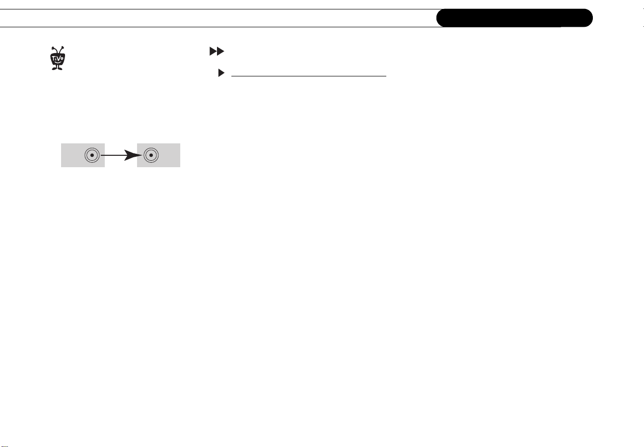
emember, always connect cables
from the OUT connector of one
®
device to the IN connector of the next.
Never connect an IN to an IN or an OUT to
an OUT.
OUT IN
Using This Guide
Step 1: Understanding the basics
TVs used to be so simple: no color, no digital video, no stereo sound, no choices. All you
needed was an antenna and a TV. The antenna captured audio and video signals. A wire,
connected from the antenna to the TV, brought these signals to your TV as sounds and
pictures.
As TVs have acquired more features, and new devices have been created to work with
your TV, it may seem that everything has become more complex. You may have a VCR,
an A/V receiver, and a game system connected to your TV, in addition to your Pioneer
DVD Recorder with TiVo
has remained the same: you still need to get the sounds and pictures from their source
(your antenna, or your cable or satellite service) to your TV.
You get the sounds and pictures to your TV by using cables. These make a path over
which the pictures and sounds travel to your TV. The choice of cables may seem
overwhelming, but they all perform the same function: they transfer sounds and pictures to
your TV at varying levels of quality.
All of your equipment has connectors, or places where cables can be connected. Some
connectors are labeled “In” and some are labeled “Out.” The pictures and sounds enter a
piece of equipment through an IN connector and leave through an OUT connector.
®
(referred to in this guide as the Recorder). However, one thing
When you connect your Recorder to your TV and other audio/video (A/V) equipment, you
are simply creating a path that starts at the wall, or your cable or satellite box, and goes in
(through IN connectors) and out (through OUT connectors) of your equipment until it
reaches your TV.
4
Page 10
Using This Guide
The R
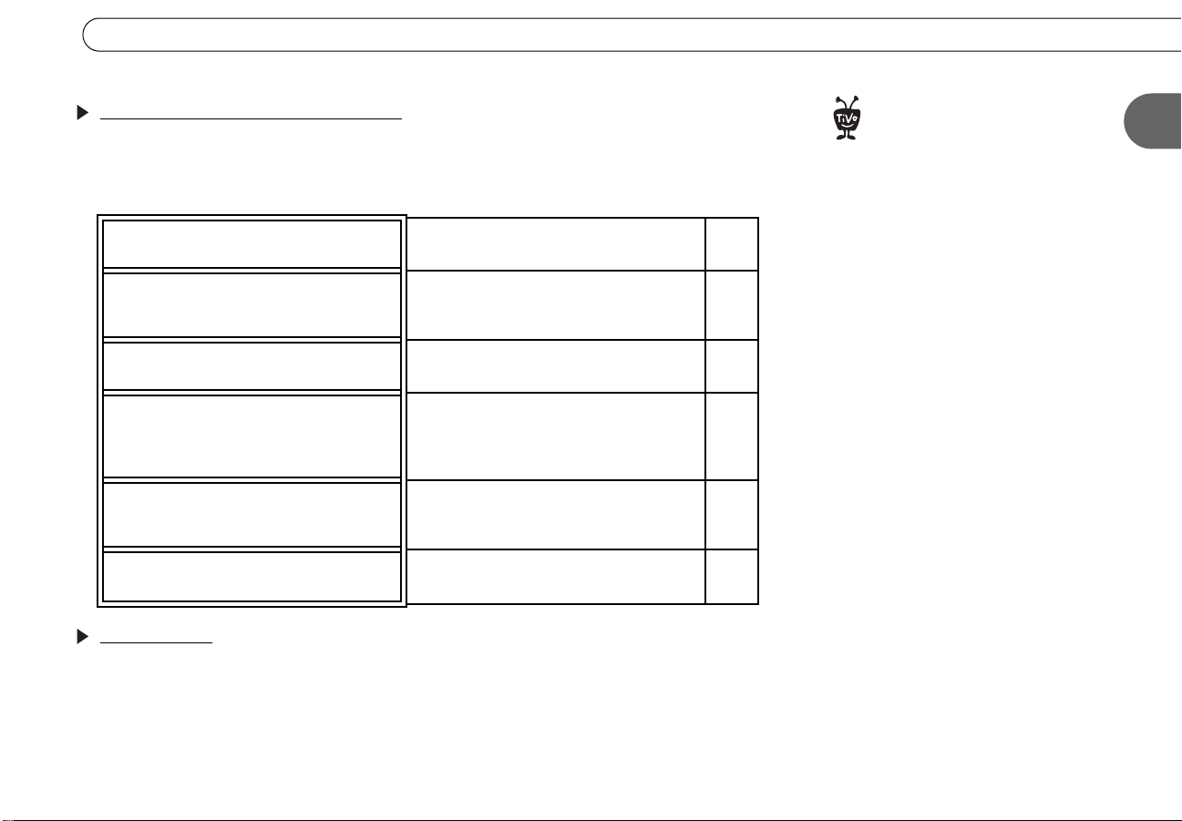
Step 2: Finding your setup example
This guide provides specific examples of connecting the Recorder to an existing antenna,
cable, or satellite system and other A/V equipment. Choose your setup example from the
ones below:
Setup 1: Antenna or Cable (No Cable
Box)
Setup 2: Cable Box or Satellite
Receiver
Setup 3: Watching One Channel
While Recording Another
Setup 4: Both a Satellite Box and an
RF Program Source
Setup 5: Both a Cable Box and a
Satellite Receiver
Setup 6: Cable or Satellite Box, A/V
Receiver, and Game Console
You use either antenna or cable without a
cable box. You may also have a VCR.
You have either a cable box or satellite
receiver (if you have both, see Setup 6
instead). You may also have a VCR.
You use either antenna or cable and want to
watch one channel while recording another.
You have both a satellite box and antenna,
or both a satellite box and cable without a
cable box. (Upgrade to TiVo Plus service
required.)
You have both a cable box and a satellite
receiver. (Upgrade to TiVo Plus service
required.)
You have an advanced home entertainment
system with several components.
p. 14
p. 16
p. 20
p. 22
p. 24
p. 26
ecorder is not designed to
support a heavy load, such as a TV.
®
Your Recorder is only capable of
supporting the weight of one or two
common A/V components such as VCRs,
DVD players, or A/V receivers (provided
they have four good, broad, padded feet
that distribute the weight near the
corners of the Recorder).
Also, avoid stacking your Recorder on top
of other electronic components—such as
DVD players, A/V receivers—or the vents
of your TV.
1
What’s next?
Connect a VCR or video camera, so you can turn your home videos into DVDs! See page
29 for instructions.
After connecting your Recorder, the last step is to complete Guided Setup; see Chapter 1
in the User’s Guide for details. You must complete Guided Setup before you can play and
record DVDs.
5
Page 11
Chapter 1
Getting Started
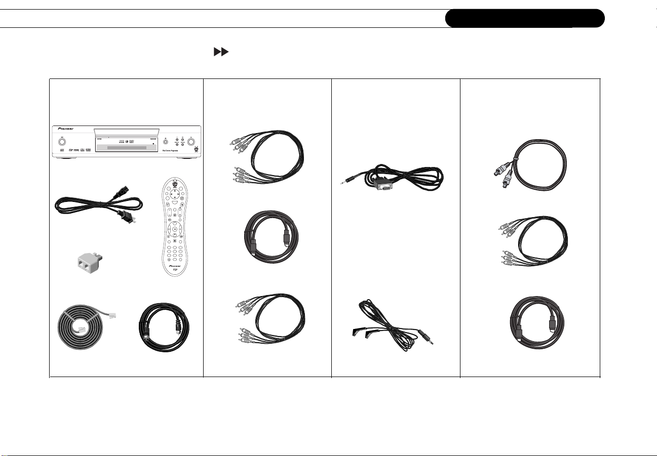
Cables and Accessories
1. These are the basics:
Recorder
Power Cord
Phone Line Splitter
25’ Phone Cord
Remote Control
RF Coaxial cable
2. See page 7 to choose
audio and video cables:
3. If you have a DIRECTV
satellite receiver with a
9-pin Data connector, or a
4. You may want to purchase
these additional cables for
some setups:
Motorola/GI DCT2000 series
cable box, use this cable:
v
e
i
L
T
V
D
G
D
e
V
u
d
i
T
u
o
n
p
I
e
n
o
M
f
W
M
w
u
e
i
o
n
n
d
S
t
e
c
l
e
M
Chan
e
u
t
Vol
Page
R
d
e
r
c
o
V
+
R
C
n
s
e
r
R
t
u
u
l
P
P
y
l
a
S
w
l
o
Stop
E
C
r
r
n
l
e
e
a
t
3
102
465
798
T
T
r
t
V
V
e
u
P
I
w
p
n
o
Composite A/V cables
S-Video cable (not supplied)
Serial (Data) Control cable*
If you can’t use the Serial
Control cable above with
your satellite receiver or
cable box, use this cable
Optical Digital Audio cable
Component Video cable
instead:
Component Video cable
(not supplied)
IR Control cable*
*See page 9 for more information and tips about Serial and IR Control.
S-Video cable
6
Page 12
Cables and Accessories
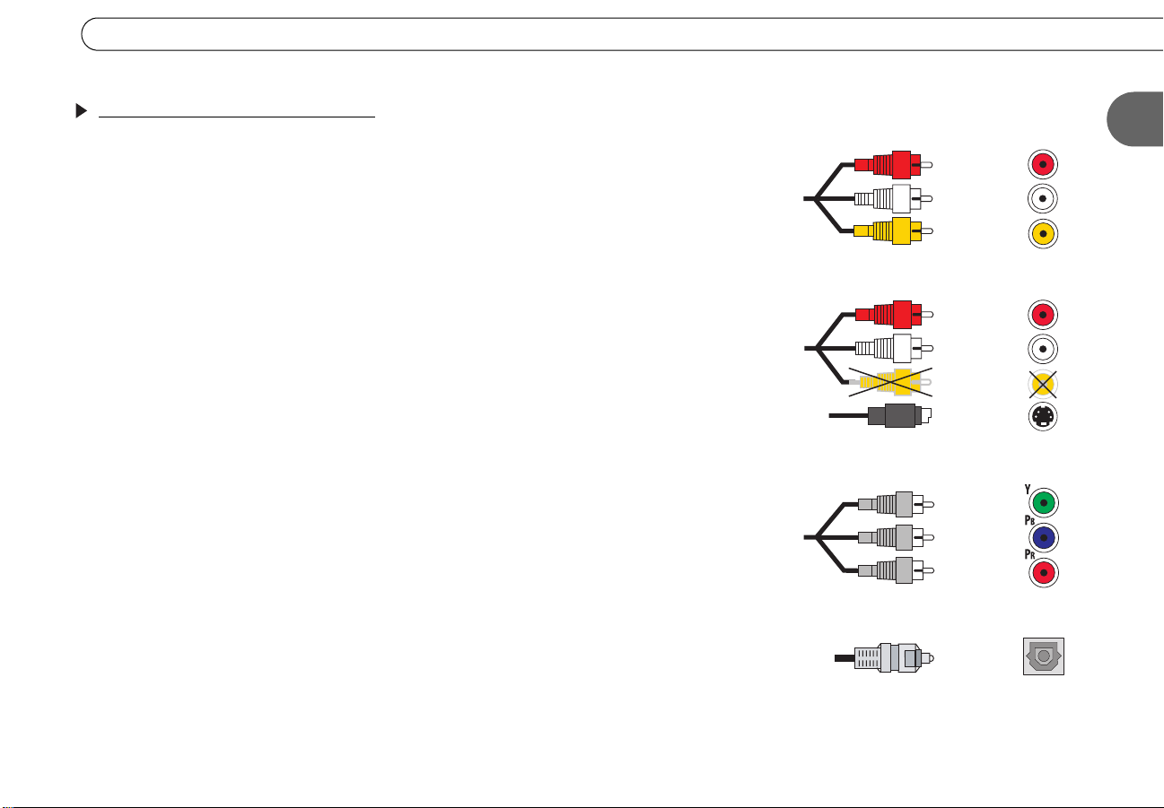
Choosing audio and video cables
The Recorder comes with a Composite A/V cable (). Composite A/V cables have three
ends, two (white and red) for L/R audio, and one (yellow) for video. Composite A/V
cables provide excellent audio and video, and you can connect the Recorder to a TV or
A/V receiver using only this cable. All of the setup diagrams in this book and the Start
Here booklet show connections using a Composite A/V cable.
The Recorder’s back panel also includes premium connectors for S-Video () and
Component Video cables (), and for a Digital Audio cable (). If you want the best
quality audio and video available and you have high end equipment that supports these
connections, you may want to purchase these additional cables to use instead of the
Composite A/V cables shown in the setup diagrams.
Premium Video. The Recorder’s premium video connectors are S-Video input and output,
and component video output. S-Video provides a higher quality signal than composite,
and component video is better still, providing the highest quality video signal generally
available in consumer electronics.
Premium Audio. The Recorder’s premium audio connector is an optical digital audio
output. Using digital audio can make a difference if you are watching DVDs with DTS
(Digital Theater Systems
you are watching DVDs with Dolby Digital
it and you want the best DVD audio signal available. See the User’s Guide for instructions
on selecting the appropriate audio settings when using this cable.
TM
) audio and you have an A/V receiver with a DTS decoder, or
TM
audio. Use it if your A/V receiver supports
Composite A/V Cable and Jacks
(red)
(white)
(yellow)
Composite L/R Audio with S-Video cable
(red)
(white)
(yellow)
(S-Video)
Component Video Cable and Jacks
(green)
(blue)
(red)
Optical Digital Audio Cable and Jack
1
You can use any combination of audio and video connectors (for example, composite
audio with S-Video, as in figure , or digital audio with component video).
7
Page 13
Chapter 1
Getting Started
Connecting to the Phone Line
You don’t need to install a new phone jack or phone number—simply use the phone line
you already have. The following information applies to all setups described in this guide:
• Phone line. Almost every household phone line is a standard analog line, which is
what the Recorder requires to complete Guided Setup. Do not connect the Recorder to
a digital PBX phone system (these allow many phones to share a single telephone
number and are usually used in hotels and office buildings). Doing so may
permanently damage your Recorder’s modem and will void your warranty.
• Phone jack. If the phone jack isn’t close to the Recorder, you can use the 25-foot
phone cord that comes with the Recorder to connect it to a phone jack. Phone cords
longer than 25 feet are readily available at most hardware or electronics stores.
Your cable or satellite box may require a connection to your phone line, too. To
connect both the Recorder and your cable or satellite box to the same phone jack, plug
the provided phone line splitter into the phone jack.
After you complete Guided Setup, you will be able to connect your Recorder to a home
network and use a shared broadband Internet connection instead of a phone line to make
connections to the TiVo service. See Chapter 8, “Connecting to a Home Network,” in the
User’s Guide.
If you don’t have a home network with a shared broadband Internet connection, the
Recorder must use a standard phone line to connect to the TiVo service. We recommend
leaving the phone cord plugged in continuously in order to keep your Recorder’s program
information up to date.
8
Page 14
Using Your Recorder with a Cable or Satellite Box
Using Your Recorder with a Cable or Satellite Box
Your Recorder needs to be able to change channels in order to record programs and
display live TV. If you are using a cable or satellite box, the Recorder sends it signals to
change the channel using either an IR (infrared) or a Serial (data) Control cable. (If you
use antenna or cable without a cable box, the Recorder does not need a Control cable to
change channels.)
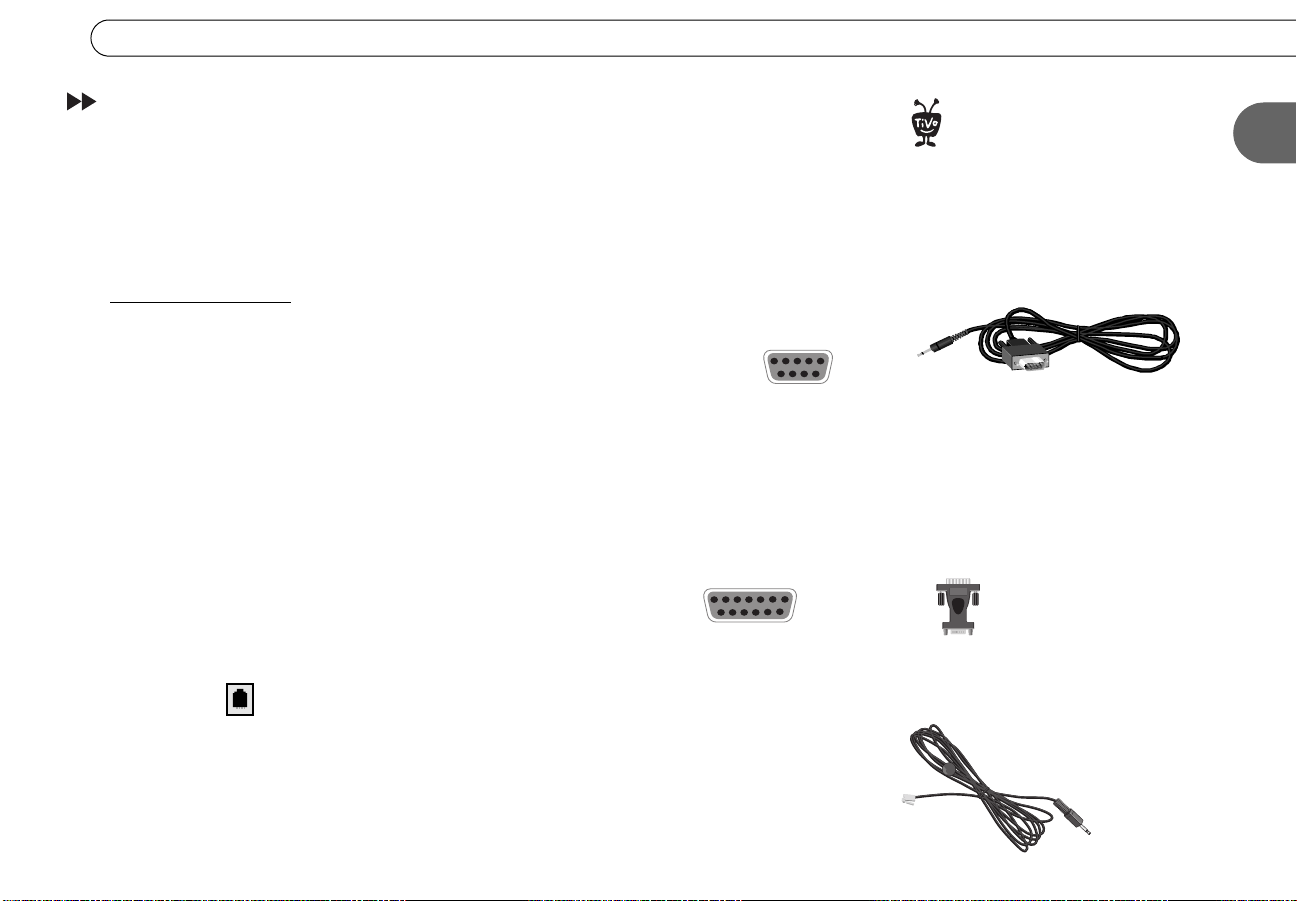
Serial/Data Control
You can use the Serial Control cable for channel changing if:
• You have a DIRECTV satellite receiver with a 9-pin data connector like this:
• You have a Motorola/General Instruments DCT2000 series cable box, and your cable
provider has enabled it for serial control.
Otherwise, use the IR Control cable (described on the next page).
Some DIRECTV satellite receivers have alternative connections that you may be able to
try. You will need to purchase an additional cable or accessory (available from
www.tivo.com/store) for these types of connections:
• If your DIRECTV satellite receiver has a 15-pin connector like this:
you can connect the Serial Control cable by using a 15-pin adapter.
• Some satellite receivers for the DIRECTV service have a Home Control connector
like this:
Home Control is the fastest and most reliable form of Control cable connection. To
connect the Home Control cable, plug one end of the cable into the Home Control jack
on your DIRECTV satellite receiver. This connector is sometimes labeled “Low Speed
Data.” (Don’t try to connect a Home Control cable to the satellite receiver’s phone
jack.) Plug the other end into the Channel Change/Serial jack on the Recorder.
(similar to a phone jack, but slightly smaller).
After setting up your Recorder,
including the Control cable
®
connection, change channels with your
Recorder’s remote control only.
Serial Control Cable
15-pin adapter
(not included)
Home Control cable
(not included)
1
9
Page 15
Chapter 1
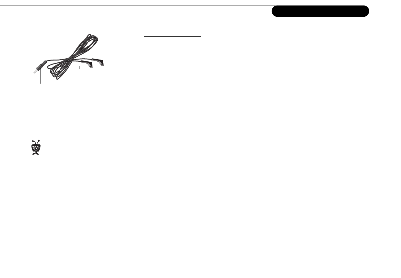
Th
IR Control cable
This purple end
plugs into your
Recorder.
e small “bulbs” on the IR
emitters do not visibly light up
®
when they send an IR signal. If you find
that channels are not changing, see
page 44 for troubleshooting help. If
channels change unreliably or
inconsistently, try the tips on optimizing
the IR Control connection (to the right).
These IR emitters
send signals to the
IR sensor on your
cable or satellite
box.
Getting Started
IR (Infrared) Control
Finding the IR sensor. To correctly position the IR Control cable, you need to find your
cable box or satellite box’s IR sensor (the connection is fully described in the examples in
Chapters 2 and 3). To locate the IR sensor, look for a tiny round bulb behind the dark,
translucent plastic “window”—the IR window—on the front of your cable or satellite box.
A flashlight might help you see it. Position the IR emitters so they are centered on the IR
sensor and stick out about 1.5 inches.
Choosing an IR code in Guided Setup. After setting up your Recorder, you’ll complete
Guided Setup (see the User’s Guide for more information). During Guided Setup, you’ll
be asked to test and select an IR code. Each IR code signals a particular cable or satellite
box model to change channels. If none of the codes changes the channel on your particular
cable or satellite box, see page 44 for troubleshooting tips. If you find a code or codes that
work, but none of the codes is reliable or consistent, try optimizing the IR Control
connection (see below).
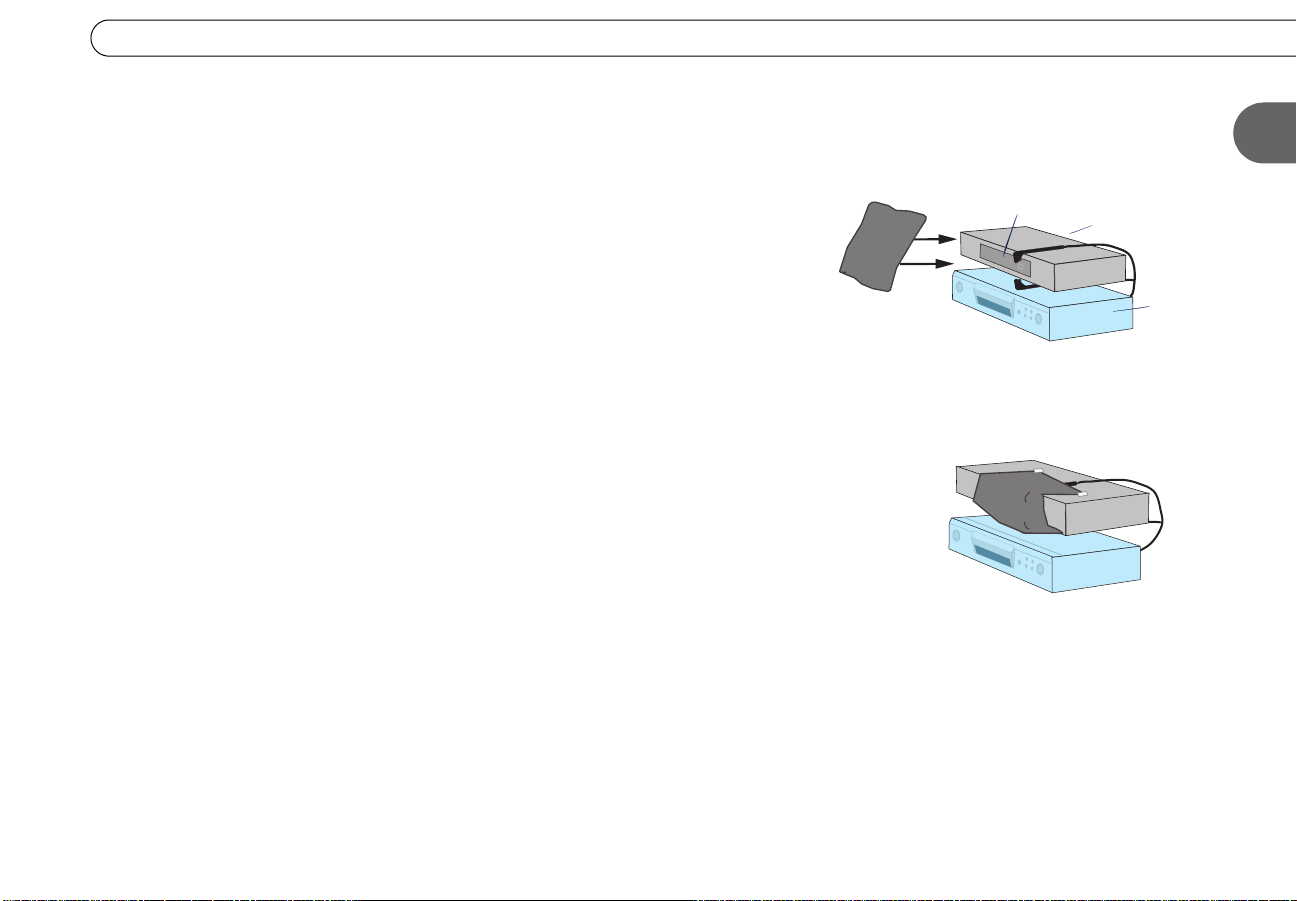
Optimizing the IR Control connection. The IR Control cable works better if its emitters
and the IR window on the cable or satellite box are shaded from other infrared signals.
You can create an IR cover to decrease the interference from other signals. This solution
may help if changing channels with an IR Control cable is unreliable or inconsistent, but
not if channels don’t change at all.
Test whether an IR cover might be effective simply by draping a magazine, a towel, or a
dark cloth over the front of cable or satellite box, including the IR emitters. (See the
diagram on page 11.) Do not block the Recorder’s IR window. Try changing channels
several times with the remote control. If channels change more reliably this way, you may
want to make an IR cover.
10
Page 16
Using Your Recorder with a Cable or Satellite Box
r
The exact methods and materials you use to build the IR cover will depend on the shape of
your cable or satellite box’s IR window and the materials you have available. However,
the general procedure described below will guide you.
1. Cover the area around the IR emitters and the cable or satellite box’s IR window with
a piece of thick fabric, such as black flannel. You could create a cover using cardboard
or opaque tape instead. The important point is that the material you use fits snugly over
the area around the translucent IR window and the IR Control cable’s emitters.
If possible, cover the entire IR window on the cable or satellite box, because signal
interference can enter from anywhere in the window. For some cable and satellite
boxes, covering the entire IR window will include covering the controls on the front.
In that case, you won’t be able to use the controls, nor will you be able to control the
cable or satellite box with its remote. However, we recommend using only your
Recorder remote control to change the channel. If you still need to access your cable or
satellite box, use materials that are relatively easy to remove.
2. Secure the cloth, tape, or other material (with tape or by another method), making sure
that it fits closely around the IR window and the IR Control cable’s emitters.
1. Place a piece of opaque material—for example,
cloth or tape—over the IR emitters (shown on
opposite page) and the IR window of the cable or
satellite box.
IR window
2. Secure the material, making sure that it fits
snugly.
cable or
satellite box
Recorde
1
11
Page 17

Chapter 1
Getting Started
12
Page 18

2
CHAPTER
2
Common Setup Examples
Setup 1: Antenna or Cable (No Cable Box) 14
Setup 2: Cable Box or Satellite Receiver 16
Page 19
Chapter 2
Before you begin:
®
• Be sure to refer to the information in
Chapter 1 of this guide.
Common Setup Examples
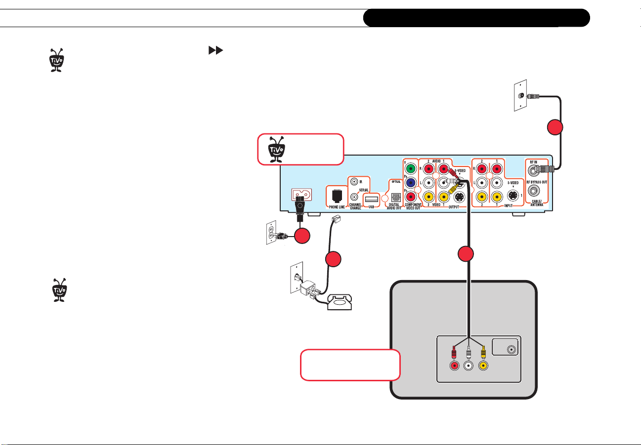
Setup 1: Antenna or Cable (No Cable Box)
• Make sure that all your equipment is
turned off and that the Recorder is
unplugged.
• The audio/video cables shown here are
for example only. For the best video
signal, you may want to use Component
Video cables instead. See page 7.
To add a VCR, see page 29. To add a
game console, use the audio/video
®
cable that came with your game console to
connect from the audio/video output on the
game console to an audio/video input on
the TV. You do not need to connect your
game console to your Recorder.
Recorder
®
AC IN
4
3
Television
INPUT
1
2
Antenna
In
R
VIDEO
L
14
Page 20

Setup 1: Antenna or Cable (No Cable Box)
1. Connect the RF Coaxial cable currently coming from the wall to the connector labeled
RF In on the Pioneer DVD Recorder with TiVo.
2. Connect the Composite A/V cable from the Audio/Video Output 1 connectors on the
Recorder to the Audio/Video Input connectors on the TV.
3. Connect a phone line (see page 8 for help). After you complete Guided Setup (see step
6 below), you’ll be able to connect your Recorder to a home network and use a shared
broadband Internet connection instead of a phone line to connect to the TiVo service.
See Chapter 8, “Connecting to a Home Network,” in the User’s Guide.
4. Plug in all power cords.
5. Turn on your TV. If you do not see the Welcome screen displayed, use the Input,
Source, or TV/Video button on your TV to select the correct audio/video source. Press
the button until the Welcome screen is displayed. (For more help, see page 42.)
6. Once you see the Welcome screen, the last step is to complete Guided Setup (see the
User’s Guide for details). You must complete Guided Setup before you can play and
record DVDs.
2
15
Page 21

Chapter 2
Before you begin:
®
• Be sure to refer to the information in
Chapter 1 of this guide.
• Make sure that all your equipment is
turned off and that the Recorder is
unplugged.
Common Setup Examples
Setup 2: Cable Box or Satellite Receiver
Cable Box or
Satellite Receiver
RF OutRF In
1
6
Audio/Video OutSerial
2
8
• The audio/video cables shown here are
for example only. For the best video
signal, you may want to use Component
Video cables instead. See page 7.
To add a VCR, see page 29. To add a
game console, use the audio/video
®
cable that came with your game console to
connect from the audio/video output on the
game console to an audio/video input on
the TV. You do not need to connect your
game console to your Recorder.
16
Recorder
®
AC IN
8
4
Television
INPUT
3
Antenna
In
R
VIDEO
L
Page 22

Setup 2: Cable Box or Satellite Receiver
1. Check that the cable from the wall is connected to the cable or satellite box.
2. Connect the Composite A/V cable from the Audio/Video Output connectors on the
cable or satellite box to the Audio/Video Input 1 connectors on the Recorder.
3. Connect the Composite A/V cable from the Audio/Video Output 1 connectors on the
Recorder to the Audio/Video Input connectors on the TV.
4. Connect a phone line (see page 8 for help). After you complete Guided Setup (see step
10 below), you’ll be able to connect your Recorder to a home network and use a shared
broadband Internet connection instead of a phone line to connect to the TiVo service.
See Chapter 8, “Connecting to a Home Network,” in the User’s Guide.
5. Select a channel changing Control cable (see page 9 for help). You can use the Serial
Control cable if you have a DIRECTV satellite receiver with a 9-pin data connector, or
a Motorola/General Instruments DCT2000 series cable box. If you choose the Serial
Control cable, continue with step 6. For any other satellite receiver or cable box,
choose the IR Control cable and skip to step 7.
6. Connect the Serial Control cable. Plug one end of the Serial Control cable into the
Data connector on the satellite receiver or cable box. Plug the other end into the
Channel Change/Serial connector (the lower mini-jack) on the Recorder. Then skip
to step 10.
7. Connect the IR Control cable. (Skip this step if you completed step 6 above.)
(a) Plug the purple end of the IR Control cable into the Channel Change/IR connector
(the upper mini-jack) on the Recorder. (b) Locate the IR sensor (see page 9 for help).
(c) Mount the IR emitters. Place one emitter on top of the cable box and the other
underneath it. Be sure both emitters stick out about 1.5 inches directly in front of the
IR sensor. (Use the provided adhesive strips to hold the emitters in place.)
For tips on the IR Control cable
connection, see page 10.
®
IR Control cable connection
7
extends 1½ "
Cable Box or
Satellite Receiver
b
Recorder
®
c
2
a
17
Page 23

Chapter 2
Common Setup Examples
8. Plug in all power cords.
9. Turn on your TV. If you do not see the Welcome screen displayed, use the Input,
Source, or TV/Video button on your TV to select the correct audio/video source. Press
the button until the Welcome screen is displayed. (For more help, see page 42).
10. Once you see the Welcome screen, the last step is to complete Guided Setup (see the
User’s Guide for details). You must complete Guided Setup before you can play and
record DVDs.
18
Page 24

3
CHAPTER
3
Additional Setup Examples
Setup 3: Watching One Channel While Recording Another 20
Setup 4: Both a Satellite Box and an RF Program Source 22
Setup 5: Both a Cable Box and a Satellite Receiver 24
Setup 6: Cable or Satellite Box, A/V Receiver, and Game Console 26
Connecting a VCR or a Video Camera 29
Page 25

Chapter 3
Before you begin:
®
• Be sure to refer to the information in
Chapter 1 of this guide.
• Make sure that all your equipment is
turned off and that the Recorder is
unplugged.
• The audio/video cables shown here
are for example only. For the best
video signal, you may want to use
Component Video cables instead. See
page 7.
Additional Setup Examples
Setup 3: Watching One Channel While Recording Another
1
Recorder
®
AC IN
5
4
Television
3
2
To add a VCR or a video camera,
see page 29.
®
20
R
VIDEO
L
Use this setup if you have antenna or cable without a cable box.
Antenna
In
INPUT
Page 26

Setup 3: Watching One Channel While Recording Another
1. Connect the RF Coaxial cable coming out of the wall to the RF In connector on the
Pioneer DVD Recorder with TiVo.
2. Connect an RF Coaxial cable from the RF Bypass Out connector on the Recorder to
the Antenna/RF In connector on the TV.
3. Connect a Composite A/V cable from the Audio/Video Output 1 connectors on the
Recorder to the Audio/Video Input connectors on the TV.
4. Connect a phone line (see page 8 for help).
5. Plug in all power cords.
6. Turn on your TV. If you see the Welcome screen, you’re ready for the next step,
below. If not, you need to find the correct input settings by pressing the Input, Source,
or TV/Video button on your TV’s remote control until you see the Welcome screen.
For more help, see page 42.
7. Once you see the Welcome screen, the last step is to complete Guided Setup (see the
User’s Guide for details). You must complete Guided Setup before you can play and
record DVDs.
To watch one channel while the Recorder records another, press the Input, Source, or TV/
Video button on your TV to select the Antenna/RF In input. You should see live TV
instead of TiVo screens. Use your TV’s remote to change the channel. Keep in mind that
there is no TiVo service functionality on any video signal coming from the Recorder’s
RF Bypass Out jack, so you will not be able to pause or rewind live TV while you are
watching one channel and recording another.
You can also watch one channel
while recording another if you have
®
a cable box. In step 1, connect an RF
Coaxial cable from your cable box to the
RF In connector on the Recorder. Then,
continue with step 2.
Keep in mind that the RF Coaxial cable
that connects from the Recorder’s
RF Bypass Out to your TV carries only your
basic cable channels. Also, you will not
have TiVo service functionality on those
channels.
3
To watch video from your Recorder again: First, press the TiVo button so that the
Recorder displays TiVo Central
®
. Then press the Input, Source, or TV/Video button on
your TV until you see TiVo Central.
21
Page 27

Chapter 3
Before you begin:
®
• Upgrade to TiVo Plus service is
required.
program source like this one are only
available after upgrading to TiVo Plus
service. To upgrade, visit
www.tivo.com/upgrade.
• Be sure to refer to the information in
Chapter 1 of this guide.
• Make sure that all your equipment
is turned off and that the Recorder is
unplugged.
• The audio/video cables shown here
are for example only. For the best
video signal, you may want to use
Component Video cables instead. See
page 7.
Set ups with more t han one
Additional Setup Examples
Setup 4: Both a Satellite Box and an RF Program Source
Satellite Receiver
INPUT
Audio/Video OutSerial
8
2
3
4
Antenna
In
Recorder
®
AC IN
RF OutRF In
1
6
8
5
To add a VCR or a video camera,
see page 29.
®
22
Television
R
VIDEO
L
Page 28

Setup 4: Both a Satellite Box and an RF Program Source
1. Make sure the satellite cable from the wall is connected to the satellite box.
2. Connect a Composite A/V cable from the Audio/Video Output connectors on the
satellite box to the Audio/Video Input 1 connectors on the Recorder.
3. Connect the RF Coaxial cable from the antenna or cable source to the RF In connector
on the Recorder.
4. Connect Composite A/V cables from the Audio/Video Output 1connectors on the
Recorder to the Audio/Video Input connectors on the TV.
5. Connect a phone line (see also page 8).
6. Connect the Serial Control cable. If your DIRECTV satellite receiver
has a 9-pin Data connector, plug one end of the Serial Control cable
into the Data connector,
and other end into the Channel Change/Serial
connector on the Recorder. Then skip to step 8.
Data
Connector
3
IR Control cable connection
7
If you don’t have a Data connector, see page 9 for Serial control alternatives. If you
still can’t use a Serial connection or if you don’t have DIRECTV service, go to step 7.
7. Connect the IR Control cable. (Skip this step if you completed step 6 above.)
(a) Plug the purple end of the IR Control cable into the Channel Change/IR connector
(the upper mini-jack) on the Recorder. (b) Locate the IR sensor (see page 9). (c) Mount
the IR emitters. Place one emitter on top of the satellite box and the other underneath
it. Be sure both emitters stick out about 1.5 inches directly in front of the IR sensor.
(Use the provided adhesive strips to hold the emitters in place.)
8. Plug in all power cords and turn on your TV. If you don’t see the Welcome screen, you
need to find the correct TV input setting. Press the Input, Source, or TV/Video button
on your TV until you see the Welcome screen. For more help, see page 42.
9. Once you see the Welcome screen, the last step is to complete Guided Setup (see the
User’s Guide for details).You must complete Guided Setup before you can play and
record DVDs.
Cable Box or
Satellite Receiver
b
extends 1½ "
c
Recorder
®
For tips on the IR Control cable
connection, see page 10.
®
a
23
Page 29

Chapter 3
.
Before you begin:
®
Additional Setup Examples
Setup 5: Both a Cable Box and a Satellite Receiver
• Upgrade to TiVo Plus
service is required.
Setups
with more than one program source
like this one are only available after
upgrading to TiVo Plus service. To
upgrade, visit
upgrade
www.tivo.com/
.
• Be sure to refer to the information in
Chapter 1 of this guide.
• Make sure that all your equipment
is turned off and that the Recorder is
unplugged.
• The audio/video cables shown here
are for example only. For the best
video signal, you may want to use
Component Video cables. See page 7
Satellite Receiver
RF OutRF In
1
®
Recorder
Cable Box
Audio/Video OutSerial
RF OutRF In
1
6
AC IN
2
3
8
INPUT
4
Antenna
In
R
VIDEO
L
5
Television
Audio/Video OutSerial
To add a VCR or a video camera,
see page 29.
®
24
Page 30

Setup 5: Both a Cable Box and a Satellite Receiver
1. Make sure the cables from the wall are connected to your cable and satellite boxes.
2. Connect a Composite A/V cable from the Audio/Video Output connectors on the
satellite box to the Audio/Video Input 1 connectors on the Recorder.
3. Connect an RF Coaxial cable from the RF Out connector on the cable box to the RF IN
connector on the Recorder.
4. Connect Composite A/V cables from the Audio/Video Output 1 connectors on the
Recorder to the Audio/Video Input connectors on the TV.
5. Connect a phone line (page 8).
6. Connect the Serial Control cable. If your DIRECTV satellite receiver
has a 9-pin Data connector, plug one end of the Serial Control cable
into the Data connector,
and other end into the Channel Change/Serial
connector on the Recorder. Then skip to step 8.
If you don’t have a Data connector, see page 9 for Serial control alternatives. If you
still can’t use a Serial connection or if you don’t have DIRECTV service, go to step 7.
7. Connect the IR Control cable. (a) Plug the purple end of the IR Control cable into the
Channel Change/IR connector (the upper mini-jack) on the Recorder. (b) Locate your
satellite and cable box’s IR sensors (see page 9). (c) Mount the IR emitters. Place one
emitter on top of the cable box. If you connected the Serial Control cable in step 6,
mount the other IR emitter underneath the cable box. If you didn’t connect the Serial
Control cable in step 6, mount the other IR emitter on top of the satellite box. Be sure
both emitters stick out about 1.5 inches directly in front of the IR sensors. (Use the
provided adhesive strips to hold the emitters in place.)
8. Plug in all power cords and turn on your TV. If you don’t see the Welcome screen, you
need to find the correct TV input setting. Press the Input, Source, or TV/Video button
on your TV until you see the Welcome screen. For more help, see page 42.
9. Once you see the Welcome screen, the last step is to complete Guided Setup (see the
User’s Guide for details). You must complete Guided Setup before you can play and
record DVDs.
Data
Connector
IR Control cable connection
7
Satellite Box
b
Cable Box
b
Recorder
®
®
IR cable connection. For tips on the IR
Control cable connection, see page 10.
c
c
The illustration above shows both
the cable and satellite box using an
3
a
25
Page 31

Chapter 3
Before you begin:
®
Additional Setup Examples
Setup 6: Cable or Satellite Box, A/V Receiver, and Game Console
• Be sure to refer to the
information in Chapter 1
of this guide.
• Make sure that all your
equipment is turned off and
that the Recorder is
unplugged.
• The audio/video cables shown
here are for example only. For
the best video signal, you may
want to use Component Video
cables instead. See page 7.
To add a VCR or a video camera,
see page 29.
®
Cable or
Satellite Box
Recorder
®
AC IN
8
Television
RF OutRF In
1
6
Audio/Video OutSerial
1
8
2
5
MAIN OUTPUT
Audio Video
RL
Audio Video
RL
INPUT
Audio Video
RL
3
INPUT
R
Antenna
In
VIDEO
L
A/V Receiver
Audio Video
RL
4
Audio Video
RL
Game Console
OUTPUT
26
Page 32

Setup 6: Cable or Satellite Box, A/V Receiver, and Game
1. Cable or Satellite Box to Recorder
Make sure the cable from the wall is connected to your cable or satellite box. Connect
a Composite Video and Left/Right Audio cable from the Audio/Video Out connectors
on the cable or satellite box to the Audio/Video Input 1 connectors on the Recorder.
(If you have cable, but don’t have a cable or satellite box, connect the RF Coaxial
cable currently coming from the wall to the connector labeled RF IN on the Recorder.)
2. Recorder to A/V Receiver
Connect Composite A/V cables from the Audio/Video Output 1 connectors on the
Recorder to the Audio/Video Input connectors on the A/V receiver. If the A/V
Receiver has a Digital Audio Input, you can connect a digital audio cable (not
supplied) from the Recorder’s Digital Audio Out to the A/V receiver.
3. A/V Receiver to TV
Connect Composite A/V cables from the Audio/Video Output connectors on the A/V
receiver to the Audio/Video Input connectors on the TV.
4. Game Console to A/V Receiver
Connect Composite A/V cables from the Audio/Video Output connectors on the
Game Console to the Audio/Video Input connectors on the A/V receiver.
5. Connect a phone line (see page 8).
6. Connect the Serial Control cable. If your DIRECTV satellite receiver
has a 9-pin Data connector, plug one end of the Serial Control cable
into the Data connector, and other end into the Channel Change/Serial
connector on the Recorder. Then skip to step 8.
If you don’t have a Data connector, see page 9 for Serial control alternatives. If you
still can’t use a Serial connection or if you don’t have DIRECTV service, go to step 7.
Data Connector
3
27
Page 33

Chapter 3
Additional Setup Examples
IR Control cable connection
7
extends 1½ "
Cable Box or
Satellite Receiver
b
For tips on the IR Control cable
connection and for alternatives to
®
the Serial Control cable, see page 9.
Recorder
®
c
7. Connect the IR Control cable. (Skip this step if you completed step 8 above.)
(a) Plug the purple end of the IR Control cable into the Channel Change/IR connector
(the upper mini-jack) on the Recorder. (b) Locate the IR sensor (see page 9). (c) Mount
the IR emitters. Place one emitter on top of the cable box and the other on top of the
satellite box. Be sure both emitters stick out about 1.5 inches directly in front of the IR
sensor. (Use the provided adhesive strips to hold the emitters in place.)
8. Plug in all power cords, and turn on your TV and your A/V receiver. Select the input
for the Recorder. If you do not currently see the Welcome screen, you’ll need to select
a
the input for your Recorder on your A/V receiver. (See the manual that came with your
A/V receiver for instructions on how to choose an input. Some A/V receivers have one
Input button that cycles through the inputs. Others have multiple input buttons, one for
each input.) If you still don’t see the Welcome screen, press the TV/Video, Source, or
Input button on your TV until you see the Welcome screen. For more help, see page
42.
9. Once you see the Welcome screen, the last step is to complete Guided Setup (see the
User’s Guide for details). You must complete Guided Setup before you can play and
record DVDs
28
Page 34

Connecting a VCR or a Video Camera
Connecting a VCR or a Video Camera
For detailed instructions on how to record from a VCR or a video camera, see Chapter 3,
“Playing and Recording Programs” in the User’s Guide. You must use Audio/Video
Input 2 on the Recorder to connect a VCR or a video camera.
To conne c t a V C R:
1. Connect a Composite A/V cable
from the Audio/Video Output 2
connector on the Recorder to the
Audio/Video Input connector on
the VCR. This will allow you to
copy recorded programs to video
tapes.
Recorder
®
AC IN
1
2
Before you begin:
®
• Be sure to refer to the information in
Chapter 1 of this guide.
• This diagram only shows connections
to the VCR. You must first complete
one of Setups shown in this Guide
before connecting a VCR or video
camera.
3
2. Connect another Composite A/V
VCR
cable from the Audio/Video
Output connector on the VCR to
the Audio/Video Input 2
connector on the Recorder. This
will allow you to transfer
recordings from video tapes to
Television
INPUT
VIDEORL
Antenna
In
the Recorder (so you can turn
your home videos into DVDs).
3. To watch video tapes on your VCR, connect an RF Coaxial cable from the RF Out
connector on the VCR to the Antenna/RF In connector on the TV. Then press the
Input, Source, or TV/Video button on your TV until you see channel numbers
3
To connect a video camera instead
of a VCR, see page 30.
®
29
Page 35

Chapter 3
Additional Setup Examples
displayed. Tune your TV to channel 3 or 4, depending on how you set the channel 3/4
switch on your VCR.
To connect a video camera (not shown):
1. If you don’t have any device connected to the Recorder’s Audio/Video Input 2, skip
to the next step. If you normally have a VCR connected to the Audio/Video Input 2
connector, you will have to disconnect it temporarily. Remove the Composite A/V
cable from the VCR’s Audio/Video Output. You can use this same cable to connect
your video camera, since it is already connected to the Recorder’s Audio/Video
Input 2.
2. Connect a Composite A/V cable from the Audio/Video Output connector on the video
camera to the Audio/Video Input 2 connector on the Recorder. This will allow you to
transfer recordings from a video camera to the Recorder (so you can turn your home
videos into DVDs). See Chapter 3, “Playing and Recording Programs” in the User’s
Guide for details.
30
Page 36

CHAPTER
4
Setting Up the Remote Control
Introduction 32
Instructions: Power, Volume, Mute, TV Input 33
Managing Multiple Recorders and Remotes 37
Resetting the Programmable Buttons 38
Page 37

Chapter 4
V
D
T
o
p
e
M
M
e
n
R
C
T
V
The TV INPUT button can control
the video signal—or “input”—your
®
TV displays. Changing the input changes
the source of the video displayed on your
TV. TV inputs can include video from a
CR, Recorder, or a video camera.
D
V
u
n
u
Vol
e
r
t
u
r
l
e
a
102
465
798
e
P
w
o
v
e
i
L
T
V
G
e
u
d
i
I
n
o
f
W
w
i
o
n
d
S
t
e
c
l
e
M
Chan
e
u
t
Page
R
d
e
r
c
o
V
+
C
n
s
R
u
l
P
P
y
l
a
S
w
l
o
Stop
E
r
n
e
t
3
T
r
t
V
u
I
p
n
Setting Up the Remote Control
Introduction
Before programming the remote control, you must first:
1. Insert batteries. See the inside front cover of the User’s Guide for instructions.
2. Complete Guided Setup. See the User’s Guide for instructions.
Using the Remote with a TV and A/V Stereo System
The remote control will already work with your Pioneer DVD Recorder with TiVo. You
can also set it up to control your TV and A/V stereo system. For example:
• Control TV power, volume, mute, and input settings: Complete the instructions on
pages 33–35 using the first column in each of the tables (TV power, volume, mute, and
TV input). To control just the TV input, follow the instructions using the second
column (TV input).
• Control TV and A/V receiver power; A/V stereo system volume and mute: Complete
the instructions on pages 33–35 using the first column in each of the tables. Then
repeat the instructions using the third column (A/V receiver power, volume, and
mute). In this case, the TV POWER button turns on/off the TV and the A/V receiver at
the same time. The VOLUME and MUTE buttons control only the A/V receiver.
• Control TV power and A/V stereo system volume and mute: Complete the
instructions on pages 33–35 using the first column in each of the tables. Then repeat
the instructions using the fourth column (A/V receiver volume and mute). The
VOLUME and MUTE buttons control only the A/V receiver.
32
Page 38

Instructions: Power, Volume, Mute, TV Input
Instructions: Power, Volume, Mute, TV Input
1. Go to the Remote Control Setup screen. Press the TiVo button; then highlight and
select Messages & Setup, then Settings, then Remote Control. Choose which device/
functions you want to control:
To Co nt rol:
Choose:
TV power, volume,
mute, and TV
Input
Remote Control - TV
(power, volume, mute)
TV input only A/V system
power
Remote Control TV (TV Input)
Remote Control A/V Stereo Receiver
A/V system
volume and
mute
Remote Control A/V Stereo Receiver
2. Select the brand of your device. Using the UP/DOWN arrows, highlight the brand of
the device you wish to control, then press SELECT. (If you have been using a
universal TV remote control, select your TV or A/V receiver’s brand, not the brand of
the universal remote.) Next you’ll see a screen with four-digit codes.
3. Prepare the remote control. Point the remote away from your Recorder and cover the
front end with your hand. Refer to the table below and determine which two buttons to
press to prepare the remote. Press and hold the buttons simultaneously for about five
seconds (until the red light at the end of the remote control lights up and stays on when
you release the buttons).
To Control:
TV power, volume,
mute, and TV
Input
Press the:
TV PWR and TiVo
buttons
TV input only A/V system
power
A/V system
volume and
mute
TV INPUT and
TiVo buttons
TV PWR and TiVo
buttons
MUTE and TiVo
buttons
4
33
Page 39

Chapter 4
Setting Up the Remote Control
4. Enter a code. Use the number buttons on the remote control to enter a four-digit code
(starting with the first code in the list on the screen). After you press the fourth digit of
the code, the red light on the end of the remote control should flash. If it doesn’t, try
the next code.
5. Test the code. Point the remote towards the TV and test the button (refer to the table):
To Test the:
Press the:
If pressing the button works (e.g., turns the TV or A/V stereo system off, or changes
the TV input), the code is correct. If it does not work, repeat steps 3 and 4 using the
next code on the list. If none of the codes work, perform a code search (see below).
TV power, volume,
mute, and TV
Input
TV PWR button TV INPUT button TV PWR button MUTE button
TV input only A/V system
power
A/V system
volume and
mute
Performing a Code Search
If none of the codes listed allow you to control your device, a code search may detect the
correct code. Performing a code search can take up to 20 minutes.
1. Prepare the remote control. Point the remote away from your Recorder and cover the
front end with your hand. Refer to the table below and determine which two buttons to
press to prepare the remote. Press and hold the buttons simultaneously for about five
34
Page 40

Instructions: Power, Volume, Mute, TV Input
seconds (until the red light at the end of the remote lights up and stays on when you
release the buttons).
To Control:
Press the:
TV power, volume,
mute, and TV
Input
TV PWR and TiVo
buttons
TV input only A/V system
power
TV INPUT and
TiVo buttons
TV PWR and TiVo
buttons
A/V system
volume and
mute
MUTE and TiVo
buttons
2. Enter the search code. Refer to the table below and use the number keys on your
remote control to enter the appropriate code.
To Test:
TV power, volume,
TV input only A/V system
mute, and TV Input
Enter:
0999 0999 1999 1999
A/V system
power
volume and mute
After you press the fourth digit of the code, the red light on the end of the remote
control will flash twice, then remain on.
3. Test the remote control. Point the remote control at the TV or A/V receiver. Press
CHAN UP to test the first code. The test is successful if the TV or A/V receiver
responds (by powering off, changing input, or muting, depending on the function you
are trying to program). If there is no response, wait two or three seconds, then press
CHAN UP again. Continue doing this until the TV or A/V receiver responds.
When the TV or A/V receiver responds, press ENTER to select the current code. The
red light at the end of the remote control will flash three times to indicate that the
remote control is properly coded to control your device.
4
35
Page 41

Chapter 4
Setting Up the Remote Control
When the red light on the end of the remote control turns off, you have reached the end
of the available codes.
Unfortunately, due to the great variety of TVs and A/V stereo systems, some makes
and models are not compatible with your Recorder’s remote control. If you reach the
end of the available codes without finding a code that works with your device, you will
need to use your TV or A/V stereo system’s remote to turn it on and off, and control
the volume.
36
Page 42

Managing Multiple Recorders and Remotes
Managing Multiple Recorders and Remotes
If you have more than one Recorder in your home, or if you have another model of TiVo
DVR in addition to your Pioneer DVD Recorder with TiVo, you can match a particular
Recorder with a particular remote so that each Recorder will only respond to its own
remote. You can do this by setting the Remote Address.
1. If both Recorders are in the same room, start
by covering the IR sensor window on one
Recorder using a cloth or thick piece of paper.
This will prevent setting the Remote Address
on both Recorders simultaneously.
2. Go to the System Information screen. First, press the TiVo button, then highlight and
select Messages & Setup, then System Information. On the System Information
screen, scroll down until you see Remote Address
3. Hold down the PAUSE and TiVo buttons simultaneously for about five seconds (until
the red light at the end of the remote control lights up and stays on when you release
the buttons).
4. Use the number keys to enter any digit from 1 to 9. Press the number you have chosen
several times until you see the Remote Address change on the screen.
The IR sensor is located in this area.
.
The default Remote Address is “0”
(zero). A remote control set to
®
Remote Address “0” will control any
Recorder, and a Recorder with a Remote
Address of “0” will respond to any
remote, including some Pioneer A/V
Receiver remote controls. When you
program the remote with a new Remote
Address, it will control any Recorder with
that Remote Address, or with an address
of “0”. To ensure that your Recorder only
responds to the Recorder’s remote, set
the Remote Address to any value other
than “0” (zero).
4
5. Press the TiVo button to go to TiVo Central.
6. Repeat these steps using your second Recorder and remote control. Be sure to choose a
different number (in Step 4) for the remote address of the second Recorder.
Once you complete this process, each remote will control only the Recorder to which it is
assigned.
Remote Address
37
Page 43

Chapter 4
Setting Up the Remote Control
Resetting the Programmable Buttons
If you make a mistake, or are having difficulty, you can reset the programmable buttons.
All the remote’s buttons will return to the unprogrammed state of a new remote.
1. Prepare the remote control. Point the remote away from your Recorder and cover the
front end with your hand.
Press and hold the TV PWR button and TiVo button simultaneously until the red light
at the end of the remote control comes on, remains steady, then stays on when you
release the buttons.
2. Press THUMBS DOWN™ three times, then press ENTER. (To cancel, press CLEAR
before you press ENTER.)
38
Page 44

5
CHAPTER
5
Troubleshooting
Customer Support 40
Troubleshooting 41
Page 45

Chapter 5
Troubleshooting
Customer Support
We are dedicated to providing you with quality support and customer service. When you have a question about your
Pioneer DVD Recorder with TiVo:
1. Use this chapter.
2. Use the troubleshooting in the User’s Guide. It contains troubleshooting on the following topics:
• The Recorder’s Connections
• Channels
•Live TV
• The TiVo Service
3. Use online support. Check online customer support at www.pioneerelectronics.com. You’ll find Frequently Asked Questions, step-
by-step troubleshooting, and the ability to get interactive help from expert users.
4. Call Customer Support. After checking Troubleshooting and online Customer Support, call Pioneer Customer Support at
1-800-421-1404 if you need help with connecting your Recorder to other equipment, Guided Setup or connections to the TiVo
service, a Recorder that does not function properly, or other questions regarding the Recorder, TiVo Basic
control.
For questions about TiVo PlusTM service, or to upgrade to TiVo Plus service, call 1-877-367-8486.
40
• Recording Programs
• Parental Controls
• Audio/Video
•Networking
TM
service, or the remote
Page 46

Troubleshooting
Troubleshooting
Why does the Recorder have to be connected to a phone line?
• The Recorder needs to be connected to a phone line or to broadband Internet access to make its regular connection to the TiVo
service. This connection downloads program information, which tells the Recorder when programs are scheduled to air and on what
channel. It also downloads additional information from the TiVo service, such as service updates.
Do I need to connect the Recorder to a phone line to get TiVo Basic service?
• The Recorder comes with TiVo Basic service, which includes up to three days of program guide information. The Recorder needs to
be connected to a phone line or to broadband Internet access to make its regular connection to the TiVo service and download
updated program information, and additional information from the TiVo service.
My phone jack isn’t near the Recorder.
• The Recorder comes with a 25 foot phone cord. Phone cords longer than 25 feet are readily available at most hardware or electronics
stores.
• After Guided Setup, the Recorder can use a home network’s shared broadband Internet connection to make its regular connections to
the TiVo service. For more information, see Chapter 8, “Connecting to a Home Network,” in the User’s Guide.
Do I need to keep the phone connected all the time?
• We recommend that you leave the phone line connected all the time. It will not interfere with your other needs for the phone line, and
the Recorder’s regular connection to the TiVo service will keep its program information fully up to date.
• After Guided Setup, the Recorder can use a home network’s shared broadband Internet connection to make its regular connections to
the TiVo service. For more information, see Chapter 8, “Connecting to a Home Network,” in the User’s Guide.
41
5
Page 47

Chapter 5
What if I need to use the phone while the Recorder is connecting to the TiVo service?
• It’s unlikely that you’ll notice the Recorder’s phone calls, because its connection to the TiVo service typically lasts only about 10
minutes and will occur during evening hours. However, if you do need to use the phone while a connection is in progress, simply
pick up the phone. You will hear a sound like that of a modem dialing. Wait a few seconds, then hang up. Wait about forty-five
seconds. When you pick up the phone again, the line should be free. If it is not, just pick up and hang up again. The Recorder will
attempt another connection later.
I don’t see the Welcome Screen when I turn on my Recorder for the first time.
• Make sure cables are connected from the OUT jack of one device to the IN jack of another. Cables should never be connected from
OUT to OUT or IN to IN.
• Do not connect the Recorder to your TV using an RF Coaxial cable from the Recorder’s RF BYPASS OUT jack to the TV’s
ANTENNA/RF IN jack. You must use either a Composite A/V cable, S-Video cable, or Component Video cable to connect your
Recorder to your TV in order to see the Welcome Screen and all other Recorder screens.
• Make sure your TV is displaying the appropriate video source. You may need to use the “Input,” “Source,” “Select,” or “TV/Video”
button on your TV’s remote to change video sources. If you are having trouble changing the video source, refer to the instructions
that came with your TV.
Troubleshooting
• If your Recorder is connected to an A/V receiver or switch box, and you are having trouble finding the correct input, try connecting
it directly to the TV instead.
• The cables you are using to connect your Recorder to your TV or other equipment may be damaged or defective. Try exchanging the
cables connected to the Recorder with other cables that you know are working properly.
42
Page 48

Troubleshooting
My Recorder remote control doesn’t control my TV’s power, volume, etc.
• You must first program the Recorder’s remote control to turn your TV on and off and control its volume and mute functions. You
can also program it to control volume and mute on an A/V receiver or stereo. For more information, see “Setting Up the Remote
Control” on page 31.
My Recorder responds to my Pioneer A/V Receiver remote control.
• Some Pioneer A/V Receiver remote controls have a “DVR/VCR” button or a “VCR” button which, when pressed, may send a signal
that your Recorder responds to (for example, your Recorder may go to TiVo Central). You can program your Recorder to respond
only to the Recorder’s remote control if you wish by setting the Remote Address. See page 37 for instructions.
My Recorder remote control doesn’t work with my Recorder.
• Be sure you are using the Recorder’s remote and that you hold it so that the TiVo button points toward the Recorder.
• Press any button on the remote. Does the red light at the end of the remote flash? If not, make sure that the batteries are positioned
correctly in the remote. If they are correctly positioned, try a new set of batteries.
• You may not have the correct input selected on your TV. Use the “Input,” “Source,” “Select,” or “TV/Video” button on your TV’s
remote to change the input. If you are using an A/V receiver, you may need to select the correct input on the A/V receiver as well.
I accidentally changed channels with my cable or satellite box’s remote control.
• After you have connected the Recorder, you should use its remote control to change channels. If you use your cable or satellite box’s
remote to change the channel, the TiVo service won’t register that the channel has changed. If you accidentally change channels with
another remote, press CHAN UP or CHAN DOWN on the Recorder’s remote once. The Recorder will then be able to register the
channel.
43
5
Page 49

Chapter 5
I accidentally changed channels with my TV or VCR’s remote control.
• If you use your TV’s or VCR’s remote to change the channel, the TV will no longer display the video signal from the Recorder. To
return to viewing video from the Recorder, return to the channel that your TV or VCR was tuned to. You may also need to press the
“Input,” “Source,” “Select,” or “TV/Video” button on your TV’s remote to change the input (i.e., the video signal your TV is
displaying).
I can’t get the channel to change.
If you have cable without a cable box:
• Be sure that you are using the Recorder’s remote and that you hold it so that the TiVo button points toward the Recorder.
• Press any button on the remote. Does the red light above the TiVo button flash?
If not, make sure that the batteries are positioned correctly in the remote. If they are correctly positioned, try a new set of batteries.
• You may not have the correct input selected on your TV. Use the “Input,” “Source,” “Select,” or “TV/Video” button on your TV’s
remote to change the input. If you are using an A/V receiver, you may need to select the correct input on the A/V receiver as well.
If you have a cable or satellite box and used the IR Control cable:
• Make sure the cable or satellite box is turned on.
Troubleshooting
• Make sure you are using the Recorder’s remote control, and that you hold it so that the TiVo button points toward the Recorder, not
at the cable or satellite box.
• Refer to page 10 to verify that the IR Control cable is positioned correctly in front of the IR sensor. Also, make sure that the purple
end of the cable is plugged into the Channel Change/IR connector on the back of the Recorder.
• You may consider optimizing the IR Control connection as described on page 10.
44
Page 50

Troubleshooting
• Press the TiVo button to go to TiVo Central, then select Messages & Setup, then Settings, then Channels, then Channel Changing,
and select “Cable Box” or “Satellite Box.” Verify the IR code you chose during Guided Setup. See page 10 for more on choosing an
IR code.
• Try using the cable or satellite box’s remote to change the channel. If it doesn’t work, contact the manufacturer or service provider
for assistance.
If you have a Motorola/General Instruments DCT2000 series cable box or a DIRECTV satellite box and used the Serial Control
cable:
• Make sure the cable or satellite box is turned on.
• Verify that the Serial Control cable is plugged into the data connector on the cable or satellite box and into the Channel Change/
Serial connector on the back of the Recorder.
• Unplug the cable or satellite box from the wall, then plug it back in. Then try changing channels with the Recorder’s remote control
again.
• Try using the cable or satellite box’s remote to change the channel. If it doesn’t work, contact the manufacturer or service provider
for assistance.
• Satellite Box Only: You may have incorrectly specified the type of program guide for your DIRECTV satellite receiver during
Guided Setup. There are two types of program guides: MPG (Master Program Guide) and APG (Advanced Program Guide). During
Guided Setup, you select either Serial-MPG or Serial-APG to determine how your channels are changed.
To change this option: First, unplug the power cord for the satellite receiver and plug it back in. Next, go to TiVo Central, then
select Messages & Setup, then Settings, then Channels, then Channel Changing, and select “Serial cable.” If you originally selected
Serial-MPG, change your selection to Serial-APG. (If you originally selected Serial-APG, change it to Serial-MPG.) You can also
check the manual for your satellite receiver (as well as the satellite receiver’s system setup screen) for information on the type of
DIRECTV program guide it uses.
5
45
Page 51

Chapter 5
Troubleshooting
46
Page 52

APPENDIX
A
Front and Back Panel Reference
Front Panel Reference 48
Back Panel Reference 51
Page 53

Appendix
Appendix A
Front Panel Reference
1
2
1 — DVD Button: Press this to go to the DVD screen.
2 — Light Strip: There are three lights (LEDs) under this clear plastic strip.
• The orange “copy” light on the left comes on when the Recorder is copying a
program to a DVD.
• The blue “play” light in the middle comes on when the Recorder is playing a
recording from Now Playing or a DVD, or CD.
• The red “record” light on the right comes on when the Recorder is recording a
program to Now Playing.
35 64
48
Page 54

Front Panel Reference
3 — Status Display: The following illustration shows the placement of lights in the status
display.
For example, when you first turn on power for the Recorder, you see a “Power On”
message in the center of the display; and when the Recorder is displaying a TiVo screen,
such as TiVo Central, you see the word “TiVo.” In addition, this area reflects input from
the remote control when you use features such as searching for a title or a chapter of a
DVD.
Other useful messages:
• When playing a CD, an “S” appears for shuffle mode, an “R” for repeat. In repeat
• While copying a program from Now Playing to a DVD, the percent complete displays.
The display in this area changes to reflect the current state of the Recorder.
mode “DSC” or “TRK” also appear, depending on whether the whole disc will repeat
or only a single track.
• While watching a recording from Now Playing, the display shows how far into the
recording you are. (E.g., “1 07 00” means you have watched one hour and seven
minutes of the recording.)
• While watching live TV, the channel number appears on the right side, near the
symbol “CH.”
• When progressive mode is on, a “P” appears at the top of the display area.
A
49
Page 55

Appendix
Appendix A
• While recording a program to Now Playing, the recording’s video quality shows on
the right side of the display: “Extreme (Fine)”; SP for “High (SP)”; LP for
“Medium (LP)”; EP for “Basic (EP).”
• If a disc is in the tray, a symbol for the kind of disc appears at the top of the
display: RW for DVD-RW; R for DVD-R; V for a video DVD; CD for a CD.
4 — Disc Tray: Opens and closes when you press the EJECT button on the front panel of
the Recorder.
5 — EJECT Button ( ): Press to open or close the disc tray.
6 — Control Buttons: These buttons work just like the buttons on the Recorder’s remote
control (see the inside front cover for more information). They include:
•STOP ()
• PAUSE ( )
•PLAY ()
•SKIP FWD ( )
• SKIP BACK ( )
50
Page 56

Back Panel Reference
R
Back Panel Reference
This section provides general information about the connections on the back panel of the
Pioneer DVD Recorder with TiVo.
emember, always connect cables
from the OUT connector of one
®
device to the IN connector of the next.
Never connect an IN to an IN or an OUT to
an OUT.
2 3 5 6 7 8 10 11 13 15 1614
RF IN
AC IN
RF BYPASS OUT
CABLE/
ANTENNA
9
12
14
17
A
51
Page 57

Appendix
Appendix A
1 — AC ~ In: (Connects to A/C power.) The Recorder does not use a separate on and off
switch; plugging it into the wall socket switches it on.
2 — Phone Line: (Connects to phone line.) The Recorder uses the phone line to get
program listings and to communicate with the TiVo service. If you already have a phone
line connected to your cable box, use the provided splitter.
3 — Channel Change/Serial: (Connects to cable or satellite box; a Serial/Data connector
is not available on all cable or satellite boxes.) This connection enables the Recorder to
change channels on a cable or satellite box.
4 — Channel Change/IR: (Connects to cable or satellite box; IR stands for infrared.) This
connection enables the Recorder to change channels on your cable or satellite box. The
purple end of the IR Control cable plugs into the Recorder. The two emitters on the other
end of the cable are placed in front of the IR sensor on the cable and/or satellite box.
5 — USB: (Universal Serial Bus.) Use with a USB network adapter (not included) to
connect to a home network, then use a network’s shared Internet connection to connect to
the TiVo service. Use the connection to a home network to take advantage of the TiVo
Home Media Option premium feature package (sold separately). For more information on
using a broadband Internet connection, see Chapter 8, “Connecting to a Home Network,”
in the User’s Guide; for more information on Home Media Option, see Chapter 7, “Home
Media Option,” in the User’s Guide.
52
6 — Optical Digital Audio Output: (Connects to A/V receiver.) Use the optical digital
audio output jack to connect the Recorder to an A/V receiver with optical digital audio
input. To do so, you need an Optical Digital Audio cable (not supplied). The Recorder
supports the Dolby Digital and DTS (Digital Theater Systems) digital audio formats.
Ordinarily, the Recorder produces tones to indicate when certain buttons on the remote
Page 58

control are pressed. If you use optical digital audio output, you may not hear these tones.
You must also establish a video connection using either an S-Video cable, the yellow plug
on a Composite A/V cable, or a Component Video cable.
7 — Component Video Output: (Connects to TV.) Component video provides the highest
picture quality. You must also establish an audio connection using either the white and red
plugs on a Composite A/V cable, or an Optical Digital Audio cable.
8 — Composite Audio Outputs: (Connects to TV.) For composite audio out, connect the
white and red plugs on a Composite A/V cable to either the red and white outputs labeled
“1” or the red and white outputs labeled “2.” You must also establish a video connection
using either an S-Video cable, the yellow plug on a Composite A/V cable, or a Component
Video cable.
9— Composite Video Outputs: (Connects to TV.) Composite video provides a picture
with very good quality. You must also establish an audio connection using either the white
and red plugs on a Composite A/V cable, or an Optical Digital Audio cable.
10—S-Video Outputs: (Connects to TV.) S-Video provides a higher quality picture than
composite. You must also establish an audio connection using either the white and red
plugs on a Composite A/V cable, or an Optical Digital Audio cable.
Back Panel Reference
11 — Composite Audio Input 2: (Connects to VCR or video camera.) Plug in the red and
white ends of a Composite A/V cable to make an audio connection. You must also
establish a video connection using the yellow end on a Composite A/V cable.
12 — Composite Video Input 2: (Connects to VCR or video camera.) Plug in the yellow
end of a Composite A/V cable to make a video connection. You must also establish an
audio connection using the red and white ends of a Composite A/V cable.
A
53
Page 59

Appendix
Appendix A
13 — Composite Audio Input 1: (Connects to satellite or cable box.) Plug in the red and
white ends of a Composite A/V cable to make an audio connection. You must also
establish a video connection using either an S-Video cable or the yellow end of a
Composite A/V cable.
14 — Composite Video Input 1: (Connects to satellite or cable box.) Plug in the yellow
end of a Composite A/V cable to make a composite video connection. You must also
establish an audio connection using the red and white ends of a Composite A/V cable.
15 — S-Video Input: (Connects to satellite or cable box. An S-Video connector is not
available on all satellite or cable boxes.) You must also establish an audio connection
using the red and white ends of a Composite A/V cable.
16 — RF In: (Connects to a satellite or cable box, to cable without a box, or to antenna.)
Use this connector if you are using an RF Coaxial cable to connect the cable box (or cable
from the wall) to the Recorder.
17 — RF Bypass Out: (Connects to TV.) Any audio/video signal passed to the Recorder
through the RF In connector passes out of the Recorder through this connector. Features of
the TiVo service such as recording and control of live TV are not available on a signal
from this connector.
54
Page 60

Index
Page 61

Index
A
A/V components, stacking on Recorder 5
A/V receiver
including in setup 26
programming remote to control 32
AC In connector 52
accessories
carton contents 6
not included 6
APG 45
C
cable box
including in setup 9
why to connect 9
cables
carton contents 6
choosing a video cable 7
not included 6
cables and connectors, the basics 4
changing channels
accidentally using the wrong remote to 43, 44
watching one program while recording another 21
channel change/IR connector 52
channel change/serial connector 52
code search, performing 34
component video cable, when to choose 7
component video output connectors 53
composite A/V cables, when to choose 7
composite video output connectors 53
control buttons, front panel 50
D
digital audio cable, when to choose. 7
digital audio output connector 52
disc tray 50
DVD button 48
E
EJECT button 50
G
game console
including in setup with A/V receiver 26
Guided Setup
choosing IR code and 10
IR Test screen and 10
when to complete 5, 21, 23, 28
I
IR code
what it does 10
L
LEDs, front panel 48
left/right composite audio input connectors 53, 54
left/right composite audio output connectors 53
M
MPG 45
MUTE button, programming 33
P
performing a code search 34
phone jack
what if it’s not close by 8
56
Page 62

phone line
analog 8
connecting the 8
digital PBX 8
not convenient to leave plugged in 8
what if cable box uses, too 8
why Recorder must be connected to 41
phone line connector 52
Pioneer DVD Recorder with TiVo
back panel reference 51
front panel reference 48
R
Recorder
stacking things on top 5
remote control
incompatibility with some makes and models 36
not working with TV 43
performing a code search 34
programmable buttons, resetting 38
responding to Pioneer A/V Receiver remotes 37, 43
setting the Remote Address 37
using with both TV and A/V equipment 32
RF Bypass Out connector 21, 54
RF In connector 54
RF splitter 20
S
satellite box
setting up 22
satellite receiver, with serial control 45
serial control cable 45
setup example
both a cable box and a satellite box 22
cable or satellite box, A/V receiver, and game console 26
finding yours 5
watching one channel while recording another 20
splitting the signal 20
stacking objects on Recorder 5
status display, front panel 49
S-Video cable, when to choose 7
S-Video input connector 54
S-Video output connectors 53
T
TiVo service
functionality on signal from RF Bypass Out jack 21
TV INPUT button, programming 33
TV PWR button, programming 33
U
USB connector 52
V
VCR, connecting a 29
video camera, connecting a 29
VOLUME button, programming 33
W
weight, supporting of on Recorder 5
57
Page 63

Index
58
Page 64

Specifications
Video In: S-Video 4-pin mini DIN
Composite Video RCA (2 pairs)
Video Out: S-Video 4-pin mini DIN (2 pairs)
Composite Video RCA (2 pairs)
Component Video RCA
Audio Line In: Stereo L/R RCA (2 pairs)
Audio Line Out: Stereo L/R RCA (2 pairs)
Digital Audio (Optical)
RF In: F-Connector Female
RF Bypass Out: F-Connector Female
Expansion Port: USB
Telephone: RJ-11 female, 2-wire
Control Change: 3.5mm mini jack sockets (2 pairs)
Power: AC 120V 60Hz
Power consumption: 49 Watts
Ambient (external) Operating Temperature: 5C to 35C
Operating Humidity: 85% or less
Dimensions: 420mm W x 94mm H x 391mm D
Actual recording capacity depends
on signal quality and the type of
®
programming being recorded.
Remote Control: 39 Buttons
Storage: ATA/IDE Hard Drive
Page 65

We are dedicated to providing you with quality support and customer service. If
you have questions or difficulties, we would like to hear from you.
TROUBLESHOOTING
Check the Troubleshooting section of this document and of the User's Guide that came with
your Recorder.
CONTACT CUSTOMER SUPPORT
Should this Recorder require service in the U.S.A. and you wish to locate the nearest Pioneer
Authorized Independent Service Company, or if you wish to purchase replacement parts, operating
instructions, service manuals, or accessories, please call the number shown below.
1-800-421-1404
Please do not ship your Recorder to Pioneer without first calling the Customer Support Division at the
above listed number for assistance.
Pioneer Electronics (USA) Inc.
Customer Support Division
P.O. BOX 1760, Long Beach
CA 90810-1760, U.S.A.
To upgrade to TiVo Plus™ service, visit www.tivo.com/upgrade. For questions about TiVo Plus service,
visit www.tivo.com/support.
PIONEER CORPORATION
4-1, Meguro 1-Chome, Meguro-ku, Tokyo 153-8654, Japan
PIONEER ELECTRONICS (USA) INC.
P.O. BOX 1540, Long Beach, California 90810-1540, U.S.A. TEL: (800) 421-1404
VRM1113-A
 Loading...