

查询PC33889供应商
MOTOROLA
Semiconductor Technical Data
Freescale Semiconductor, Inc.
Order this document by APD Marketing
Rev 5.6, 23th July 02
Product Preview
System Basis Chip Lite with Low
Speed Fault Tolerant CAN Interface
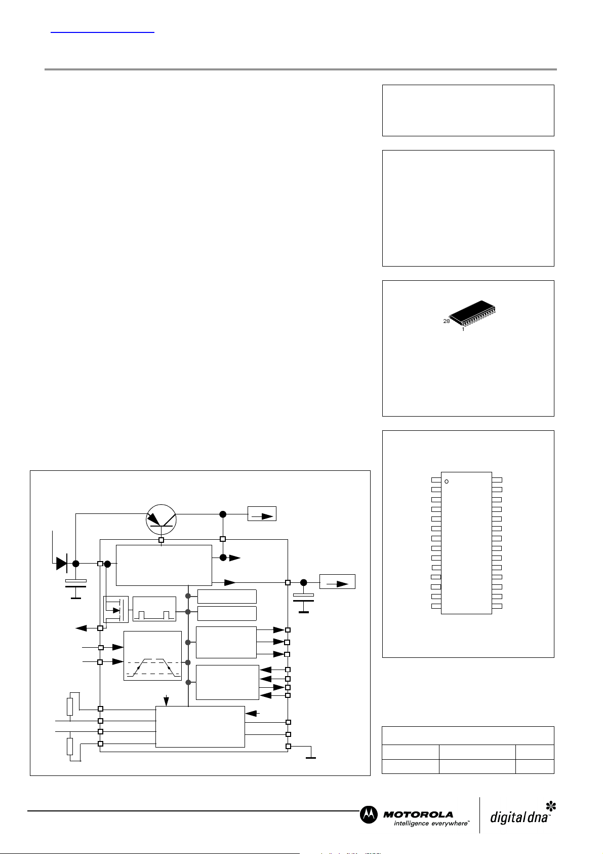
The MC33889 is a monolithic integrated circuit combining many functions
frequently used by au tomot ive ECU s. It i ncorpo rates a low sp eed fa ult toleran t
CAN physical interface.
Main features:
• Vdd1: 5V Low drop voltage regulator, current limitation, over temperature
detection, monitoring and reset function. Total current capability 200mA.
• V2: Tracking function of Vdd1 regulator. C ontrol circuitry for external bipolar
ballast transistor for high flexibility in choice of peripheral voltage and current
supply.
• Four operational m odes: norma l, stand-b y , stop and sleep modes.
• Low stand-by c urrent consum ption in s top and sle ep modes
• Built in Low speed 125KBaud fault tolerant CAN physical interface,
compatible wit h Motorol a MC33388.
nc...
I
• External high vol tage wake-u p input, as sociated with HS1 Vbat s witch
• 150mA output current cap ability for HS1 Vbat switch all owing drive of external
switches pull up resistors o r relays
• Vsup monitoring and failure detection
• DC Operating vol tage from 5 to 27V
• 40V maximum transient voltag e
• Programmable softwa re time out and window watchdog
• Separate output s for W atchdog time out sign al (WDOGB) and Reset (Res et).
• Wake up capabilities: wake up input, programmable cyclic sense, forced
wake up, CAN interface , SPI (CSB pin) and stop m ode over cur rent.
• Interface with MCU through 4 Mhz SPI.
• SO28WB package w ith thermal en hanced lea d frame.
Simplified Block Diagram
Q1
cale Semiconductor,
Vbat
Vsup
V2CTRL
Vsup monitor
Dual Voltage Regulator
Vdd1 Monitor
V2
5V/200mA
5V
CAN
supply
Frees
Mode control
Oscillator
Interrupt
Watchdog
Reset
SPI Interface
V2
Rrth
Rrtl
HS1
L0
L1
Rth
CAN H
CAN L
Rtl
HS1 control
Programmable
wake-up input
Vsup
Low Speed 125Kbit/s
Fault Tolerant CAN
Physical Interface
Vdd1
INTB
WDOGB
Reset
MOSI
SCLK
MISO
CSB
Txd
Rxd
Gnd
5V/200mA
PC33889
PASS3
System Basis
Chip Lite
SILICON MONOLITHIC
INTEGRATED CIRCUIT
DW SUFFIX
PLASTIC PACKAGE
CASE 751F
SO-28
PIN CONNECTIONS
1
RX
2
TX
3
Vdd1
4
Reset
5
INTB
6
GND
7
GND
8
GND
9
GND
10
V2ctrl
11
Vsup
12
HS1
13
L0
14
L1
ORDERING INFORMATION
Device
Operating
Temperature Range
TA = -40 to 125°CPC33889DW
28
27
26
25
24
23
22
21
20
19
18
17
16
15
WDOGB
CSB
MOSI
MISO
SCLK
GND
GND
GND
GND
CANL
CANH
Rtl
Rth
V2
Package
SO-28
This document contains information on a product under development. Motorola reserves the right
to change or discontinue this product without notice.
For More Information On This Product,
Go to: www.freescale.com
© Motorola, Inc., 2002. All rights reserved.
Freescale Semiconductor, Inc.
PC33889
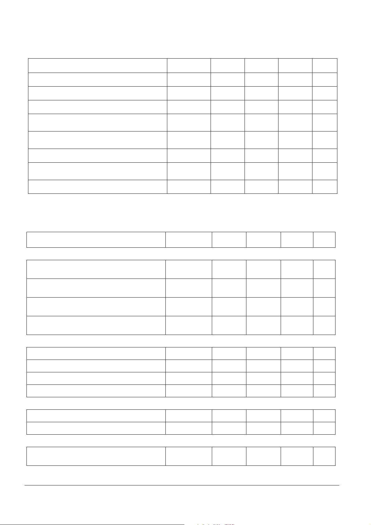
1 MAXIMUM RATINGS
Ratings Symbol Min Typ Max Unit
ELECTRICAL RATINGS
Supply Voltage at Vsup
- Continuous voltage
- Transient voltage (Load dump)
Logic Inputs (Rx, Tx, MOSI, MISO, CSB, SCLK, Reset,
WDOGB, INTB)
Output current Vdd1 I Internally limited A
HS1
- voltage
- output current
ESD voltage (HBM 100pF, 1.5k)
- CANL, CANH, Rtl, Rth, HS1, L0, L1
- All other pins
ESD voltage (Machine Model) All pins Vesdm -200 200 V
Vsup
Vsup
Vlog - 0.3 Vdd1+0.3 V
V
I
Vesdh
-0.3 27
-0.2
Internally limited
-4
-2
Vsup+0.3 V
40
4
2
V
A
kV
nc...
I
cale Semiconductor,
Frees
L0, L1
- DC Input voltage
- DC Input current
- Transient input current (according to ISO7637 specification) and with external component tbd.
CAN related pins: CANH, CANL, RTL, RTH, Tx, Rx
(refer to CAN section)
THERMAL RATINGS
Junction Temperature T
Storage Temperature T
Ambient Temperature (for info only) T
Thermal resistance junction to gnd pin (note 1) Rthj/p 20 °C/W
Note 1: gnd pins 6,7,8,9,20, 21, 22, 23.
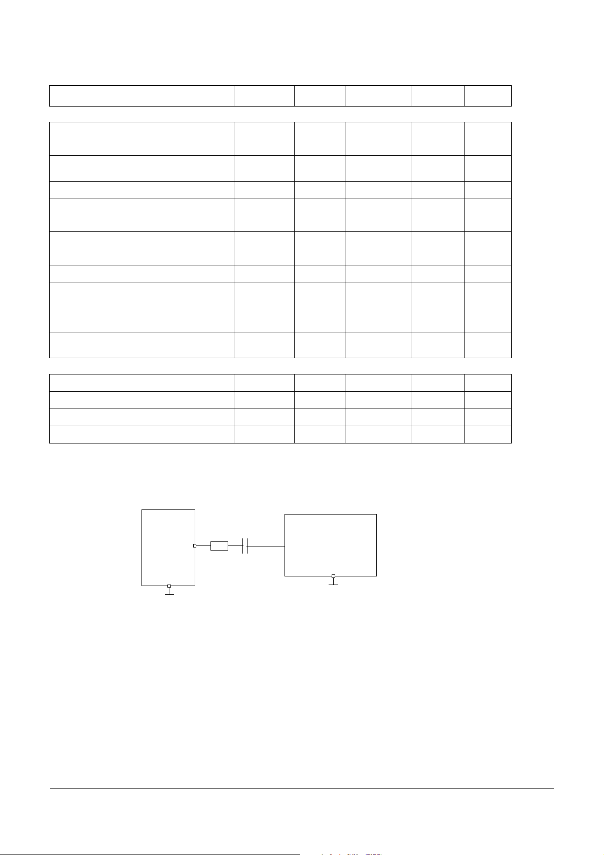
Figure 1. T ransient test pul se for L0 and L1 inputs
Lx
10 k
Gnd
1nF
Vwu DC
j
s
a
-0.3
-2
tbd
- 40 +150 °C
- 55 +165 °C
- 40 +125 °C
Transient Pulse
Generator
(note)
Gnd
40
tbd
2
mA
mA
V
note: Waveform in accordance to ISO7637 part1, test pulses 1, 2, 3a and 3b.
PC33889 2
For More Information On This Product,
Go to: www.freescale.com

Freescale Semiconductor, Inc.
2 ELECTRICAL CHARACTERISTICS
(V
From 5.5V to 18V and Tj from -40°C to 125°C) unless otherwise noted. For all pins except can related pins
sup
PC33889
nc...
I
cale Semiconductor,
Frees
Description Symbol
Vsup pin (Device power supply)
Nominal DC Voltage range
Extended DC Voltage range 1 Vsup-ex1 4.5 5.5 V Reduced functionality
Extended DC Voltage range 2 Vsup-ex2 18 27 V (note 3)
Input Voltage during Load Dump
Input Voltage during jump start
Supply Current in Sleep Mode (note 2,4)
Supply Current in Sleep Mode (note 2,4)
Supply current in sleep mode (note 2,4)
Supply Current in Stand-by Mode
(note 2,4)
Supply Current in Normal Mode (note 2)
Supply Current in Stop mode (note 2,4)
I out Vdd1 <2mA
Supply Current in Stop mode (note 2,4)
Iout Vdd1 < 2mA
Supply Current in Stop mode (note 2,4)
Iout Vdd1 < 2mA
Supply Fail Flag internal threshold Vthresh 1.5 3 4 V
Supply Fail Flag hysteresis Vdet hyst 1 V guaranteed b y design
Battery fall early warning threshold BFew 5.9 6.1 6.3 V In normal & standby mode
Battery fall early warning hysteresis BFewh 0.1 0.2 0.3 V In normal & standby mode,
note 1: Vdd1>4V, reset high, logic pin high level reduced, device is functional.
note 2: current measured at Vsup pin.
note 3: Device is fully functional. All modes available and operating, Watchdog, HS1 turn ON turn OFF, CAN cell operating, L0 and L1 inputs
operating, SPI read write operation. Over temperature may occur.
note 4: Excluding the CAN cell current. An additional 30uA typical must be added to specified value.
note 5: Oscillator running means “Forced Wake Up” or “Cyclic Sense” or “Software Watchdog” timer activated.
note 6: Vdd is ON with2mA typical output current capability.
Vsup
VsupLD
VsupJS
Isup
(sleep1)
Isup
(sleep2)
Isup
(sleep3)
Isup(stdby)
Isup(norm)
Isup
(stop1)
Isup
(stop2)
Isup
(stop3)
Characteristics
Unit Conditions
Min Typ Max
5.5 18 V
(note 1)
40 V Load dump situation
27 V Jump start situation
75 tbd uA Vdd1 & V2 off, Vsup<12V,
oscillator running (note 5)
excluding CAN current
60 tdb uA Vdd1 & V2 off, Vsup<12V
oscillator not running (note5)
excluding CAN current,
150 tbd uA Vdd1 & V2 off, Vsup>12V
oscillator running (note 5)
excluding CAN current
15 mA Iout at Vdd1 =10mA, CAN
recessive state or disabled
15 mA Iout at Vdd1 =10mA, CAN
recessive state or disabled
120 tbd uA Vdd1 on (note 6), Vsup<12V
oscillator running (note 5)
excluding CAN current,
110 tbd uA Vdd1 on (note 6), Vsup<12V
oscillator not running (note 5)
excluding CAN current
180 tbd uA Vdd1 on (note6), Vsup>12
oscillator running (note 5)
excluding CAN current
guaranteed by design
Vdd1 (external 5V output for MCU supply). Idd1 is the total regulator output current. Vdd specification with external capacitor
C>=22uF and ESR<1O ohm.
Vdd1 Output Voltage Vdd1out 4,9 5 5,1 V Idd1 from 2 to 200mA
Vdd1 Output Voltage Vdd1out 4 V Idd1 from 2 to 200mA
Drop Voltage Vsup>Vddout Vdd1drop 0.2 0,5 V Idd1 = 200mA
Drop Voltage Vsup>Vddout, limited out-
put current
Idd1 Output Current Idd1 200 270 350 mA Internally limited
Vdd1 Output Voltage in stop mode Vddstop 4,75 5,00 5,25 V Iout < 2mA
Vdd1dp2 0,1 0,25 V Idd1 = 50mA
5.5V< Vsup <27V
4.5V< Vsup <5.5V
4.5V< Vsup <27V
PC33889 3
For More Information On This Product,
Go to: www.freescale.com
(V
From 5.5V to 18V and Tj from -40°C to 125°C) unless otherwise noted. For all pins except can related pins
sup
Freescale Semiconductor, Inc.
PC33889
Description Symbol
Idd1 stop output current to wake up SBC Idd1s-wu1 2 3.5 5 mA Selectable by SPI. Default
Idd1 stop output current to wake up SBC Idd1s-wu2 10 14 18 mA Selectable by SPI
Idd1 over current wake deglitcher (with
Idd1s-wu1 selected)
Idd1 over current wake deglitcher (with
Idd1s-wu2 selected)
Thermal Shutdown Tsd 160 190
Over temperature pre warning Tpw 130 160
Temperature Threshold difference Tsd-Tpw 20 40
Reset threshold 1 Rst-th1 4.5 4.6 4.7 Selectable by SPI. Default
Reset threshold 2 Rst-th2 4.1 4.2 4.3 Selectable by SPI
Reset duration reset-dur 0.85 1 2 ms
Vdd1 range for Reset Active Vdd
nc...
I
Reset Delay Time t
Line Regulation LR1 5 25 mV 9V<V
Line Regulation LR2 10 25 mV 5.5V<V
Load Regulation LD 20 50 mV 1mA<I
Thermal stability ThermS 5 mV Vsup=13.5V, I=100mA
Idd1-dglt1 40 75 55 us Guarant eed by design
Idd1-dglt2 150 us Guarant eed by design
r
d
Characteristics
Min Typ Max
1V
520us
Unit Conditions
value after reset.
°C Normal or standby mode
°C VDDTEMP bit set
°C
value after reset.
measured at 50% of reset sig-
nal. Guaranteed by design
<18, Idd=10mA
sup
<27V, Idd=10mA
sup
<200mA
Idd
cale Semiconductor,
Frees
V2 tracking voltage regulator
note 7: V2 specification with external capacitor
- option 1: C>=22uF and ESR<1O ohm
- option2: 1uF<C<22uF and ESR<10 ohm. In this case depending upon ballast transistor gain an additional resistor and capacitor netwo rk
between emitter and base of PNP ballast transistor might be required.
V2 Output Voltage V2 0.99 1 1.01 Vdd1 I2 from 2 to 200mA
I2 output current (for information only) I2 200 mA Depending upon external bal-
V2 ctrl drive current I2ctrl tbd 10 tbd mA
Logic outpu t pi ns (MISO)
Low Level Output Voltage Vol 1.0 V I out = 1.5mA
High Level Output Voltage Voh Vdd1-0.9 V I out = -250uA
Tristated MISO Leakage Current -2 +2 uA 0V<V
Logic input pins (MOSI, SCLK, CSB)
High Level Input Voltage Vih 0.7Vdd1
Low Level Input Voltage Vil -0.3 0.3Vdd1 V
High Level Input Current on CSB Iih -100 -20 uA V
Low Level Input Current CSB Iil -100 -20 uA V
MOSI, SCLK Input Current Iin -10 10 uA 0<V
Reset Pin (output pin only)
High Level Output current Ioh -250 uA 0<V
Low Level Output Voltage (I
Low Level Output Voltage (I
Reset pull down current Ipdw 2.4 5 mA
Reset Duration after Vdd High reset-dur 1 2 ms
Wdogb output pin
=1.5mA) Vol 0 0.9 V 5.5v<V
0
=tb d mA) Vol 0 0.9 V 1v<V
0
Vdd1+0.3
V
5.5V< Vsup <27V
last transistor
<Vdd
miso
=4V
i
=1V
i
<Vdd
IN
<0.7Vdd
out
<27V
sup
dd1
PC33889 4
For More Information On This Product,
Go to: www.freescale.com

(V
From 5.5V to 18V and Tj from -40°C to 125°C) unless otherwise noted. For all pins except can related pins
sup
Freescale Semiconductor, Inc.
PC33889
nc...
I
cale Semiconductor,
Frees
Description Symbol
Low Level Output Voltage (I0=1.5mA) Vol 0 0.9 V 5.5v<V
High Level Output Voltage (I
INT Pin
Low Level Output Voltage (I
High Level Output Voltage (I
HS1: 150mA High side output pin
Rdson at Tj=25°C, and Iout -150mA Rdson25 2.5 Ohms Vsup>9V
Rdson at Tj=125°C, and Iout -150mA Rdson125 5 Ohms Vs up>9V
Rdson at Tj=125°C, and Iout -120mA Ron125-2 4 5.5 Ohms 5.5 V<Vs up<9V
Output current limitation Ilim 200 500 mA
Over temperature Shutdown Ovt 155 190
Leakage current Ileak 10 uA
Output Clamp Voltage at Iout= -1mA Vcl -1.5 -0.3 V no inductive load drive capa-
Cyclic sense period (refer to SPI) T1 ms in sleep and stop modes
Cyclic sense On time (refer to SPI) T2 100 us in sleep and stop modes
Timing accuracy (cyclic sense period and
on time)
L0 and L1 inputs
L0 Negative Switching Threshold Vth0n 1.7
L0 Positive Switching Threshold Vth0p 2.2
L1 Negative Switching Threshold Vth1n 2
L1 Positive Switching Threshold Vth1p 2.7
Hysteresis Vhyst 0.6
Input current Iin -10 10 uA -0.2V < Vin < 40V
Wake up Filter Time (enable/disable
option on L0 input)
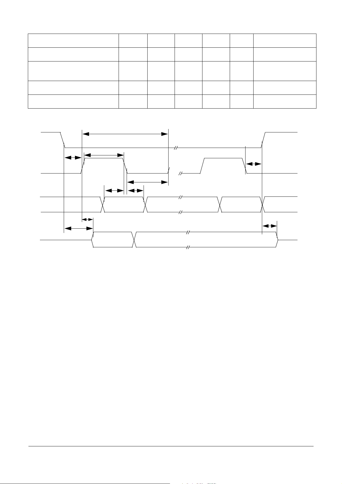
DIGITAL INTERFACE TIMING
SPI operation frequency Freq 4 MHz
SCLK Clock Period t
SCLK Clock High Time t
SCLK Clock Low Time t
Falling Edge of CS to Rising
Edge of SCLK
Falling Edge of SCLK to Rising Edge of
CS
MOSI to Falling Edge of SCLK t
Falling Edge of SCLK to MOSI t
MISO Rise Time (CL = 220pF) t
MISO Fall Time (CL = 220pF) t
=-250uA) Voh Vdd1-0.9 Vdd1
0
=1.5mA) Vol 0 0.9 V
0
=-250uA) Voh Vdd1-0.9 Vdd1
0
Tacc -30 +30 % in sleep and stop mode
pCLK
wSCLKH
wSCLKL
t
lead
t
lag
SISU
SIH
rSO
fSO
Characteristics
Min Typ Max
2
2
2.5
2.5
2.5
2.7
3
3.5
82038
250 ns
125 ns
125 ns
100 50 ns
100 50 ns
40 25 ns
40 25 ns
tbd
tbd
tbd
tbd
2.5
3
3.2
3.3
4
4.2
tbd
25 50 ns
25 50 ns
3
3
3.1
4
4
4.1
3
3.6
3.7
3.8
4.6
4.7
1.3 V 5.5V<Vsup<18V
Unit Conditions
<27V
sup
°C
bility
V 5.5V<Vsup<6V
V 5.5V<Vsup<6V
V 5.5V<Vsup<6V
V 5.5V<Vsup<6V
us
6V<Vsup<18V
18V<Vsup<27V
6V<Vsup<18V
18V<Vsup<27V
6V<Vsup<18V
18V<Vsup<27V
6V<Vsup<18V
18V<Vsup<27V
18V<Vsup<27V
(If filter enable)
PC33889 5
For More Information On This Product,
Go to: www.freescale.com

(V
From 5.5V to 18V and Tj from -40°C to 125°C) unless otherwise noted. For all pins except can related pins
sup
Freescale Semiconductor, Inc.
PC33889
nc...
I
cale Semiconductor,
Frees
Description Symbol
Time from Falling o r R isi ng Edge s of CS t o:
- MISO Low Impedance
- MISO High Impedance
Time from Rising Edge of SCLK to MISO
Data Valid
STATE MACHINE TIMING
note 1: delay starts at rising edge of CSB (end of SPI command) and start of Turn on or Turn off of HS1 or V2.
Delay between CSB low to high transition
(at end of SPI stop command) and Stop
or sleep mode activation
Interrupt low level duration Tint 7 10 13 us SBC in stop mode
Internal oscillator frequency Osc-f1 100 kHz
Internal low power oscillator frequency Osc-f2 100 kHz
Watchdog period 1 Wd1 8.58 9.75 10.92 ms Normal and standby modes
Watchdog period 2 Wd2 39.6 45 50.4 ms Normal and standby modes
Watchdog period 3 Wd3 88 100 112 ms Normal and standby modes
Watchdog period 4 Wd4 308 350 392 ms Normal and standby modes
Watchdog period accuracy F1acc -12 12 % Normal and standby modes
Normal request mode timeout NRtout 308 350 392 ms Normal request mode
Watchdog period 1 - stop Wd1stop 6.82 9.75 12.7 ms Stop mode
Watchdog period 2- stop Wd2stop 31.5 45 58.5 ms Stop mode
Watchdog period 3 - stop Wd3stop 70 100 130 ms Stop mode
Watchdog period 4 - stop Wd4stop 245 350 455 ms Stop mode
Stop mode watchdog period accuracy F2acc -30 30 % Stop mode
Cyclic sense/FWU timing 1 CSFWU1 3.22 4.6 5.98 ms Sleep and stop modes
Cyclic sense/FWU timing 2 CSFWU2 6.47 9.25 12 ms Sleep and stop modes
Cyclic sense/FWU timing 3 CSFWU3 12.9 18.5 24 ms Sleep and stop modes
Cyclic sense/FWU timing 4 CSFWU4 25.9 37 48.1 ms Sleep and stop modes
Cyclic sense/FWU timing 5 CSFWU5 51.8 74 96.2 ms Sleep and stop modes
Cyclic sense/FWU timing 6 CSFWU6 66.8 95.5 124 ms Sleep and stop modes
Cyclic sense/FWU timing 7 CSFWU7 134 191 248 ms Sleep and stop modes
Cyclic sense/FWU timing 8 CSFWU8 271 388 504 ms Sleep and stop modes
Cyclic sense On time Ton 200 350 500 us in sleep and stop modes
Cyclic sense/FWU timing accuracy Tacc -30 +30 % in sleep and stop mode
Delay between SPI command and HS1
turn on (note 1)
Delay between SPI command and HS1
turn off (note 1)
Delay between SPI and V2 turn on
(note 1)
Delay between SPI and V2 turn off
(note 1)
Delay between Normal Request and Nor-
mal mode, after W/D trigger command
t
SOEN
t
SODIS
t
valid
Tcsb-stop 18 34 us
Ts-HSon 22 us
Ts-HSoff 22 us
Ts-V2on 9 22 us St andby mode
Ts-V2off 9 22 us Normal modes
Ts-NR2N 15 35 70 us Normal request mode
Characteristics
Min Typ Max
50
50
50 ns
Unit Conditions
ns
0.2 V1≤SO≥ 0.8V1,
C
=200pF
L
Guaranteed by design
detected by V2 off
All modes except Sleep
and Stop, guaranteed by
Sleep and Stop modes,
threshold and condition to
Normal or standby mode
Normal or standby mode
design
guaranteed by design
be added
Vsup>9V
Vsup>9V
PC33889 6
For More Information On This Product,
Go to: www.freescale.com
Freescale Semiconductor, Inc.
Delay between SPI and “CAN normal
mode”
Delay between SPI and “CAN sleep
mode”
Delay between CSB wake up (CSB low
to high) and SBC normal request mode
(Vdd1 on & reset high)
Delay between CSB wake up (CSB low
to high) and first accepted SPI command
Delay between INT pulse and 1st SPI
command accepted
CSB
Ts-CANn 10 us
Ts-CANs 10 us
Tw-csb 15 40 90 us SBC in stop mode
Tw-spi 90 N/A us SBC in stop mode
Ts-1stspi 20 N/A us In stop mode after wake up
Figure 2. Timing Characteristics
Tpclk
PC33889
SBC Normal mode
guaranteed by design
SBC Normal mode
guaranteed by design
Tvalid
Twclkh
D0
Tsi s u
D0
Tsi h
Twclkl
Don’t Care
Don’t Care
Tlag
D8 Don’t Care
Tsodis
D8
Tlead
SCLK
nc...
I
MOSI
MISO
Undefined
Tsoen
cale Semiconductor,
Frees
PC33889 7
For More Information On This Product,
Go to: www.freescale.com
PC33889
Freescale Semiconductor, Inc.
3 CAN MODULE SPECIFICATION (COMPATIBLE WITH MC33388)
ELECTRICAL RA TINGS
Ratings Symbol Min Typ Max Unit
nc...
I
cale Semiconductor,
Frees
DC Voltage On Pins Tx, Rx
DC voltage at V2 (V2int)
DC Voltage On Pins CANH, CANL
Transient V oltage At Pins CANH, CANL
0 < V
Transient V oltage On Pins CANH, CANL (Coupled Through
1nF Capacitor)
DC Voltage On Pins R th, R tl
Transient V oltage At Pins R tH, R tL
0 < V
RTH, RTL Termination Resistance
Supply current described below are the CAN module internal supply current from internal V2 (V2-int) and Vsup
Internal V2 Supply Current (CAN and SBC in Normal
Mode). TX= 5V, CAN in Recessive State
Internal V2 Supply Current (CAN and SBC in Normal
Mode). TX = 0V, No Load, CAN in Dominant State
Total supply Current (CAN in Receive Only Mode, SBC in
Normal mode). Internal V2 = 5V; V
Internal V2 Supply Current (CAN in Bus TermVbat mode)
V
TX Pin
High Level Input Voltage V
Low Level Input Voltage V
< 5.5V; V
2-int
< 5.5V; V
2-int
≥ 0; T < 500ms
sup
≥ 0; T < 500ms
sup
ELECTRICAL CHARAC TERISTICS (V
Conditions Symbol Min Typ Max Unit
= 12V
sup
= 12V
sup
From 5.5V to 18V, V2int from 4.75 to 5.25V and Tj from -40°C to 150°C unless otherwise noted).
sup
Vlogic -0.3 V
V2int 0 5.25 V
V
BUS
V
CANH/VCANL
V
tr
, V
V
rtl
V
RtH/VRtL
R
I
V2-int
I
V2-int
I
+ I
V2-int
I
V2-int
ih
il
rth
t
SUP-int
-20 +27 V
-40 40 V
-150 100 V
-0.3 +27 V
-0.3 40 V
500 16000 ohm
45.66.5mA
4.2 5.8 6.7 mA
11.4mA
36 tbd uA
0.7*V
2-int
-0.3 0.3 * V
DD1
V
+ 0.3 V
+0.3V V
2-int
2-int
V
TX High Level Input Current (V
TX Low Level Input Current (V
RX Pin
High Level Output Voltage RX (I
Low Level Output Voltage (I
CANH, CANL Pins
Differential Receiver, Recessive To Dominant Threshold
(By Definition, V
diff=VCANH-VCANL
= 4V) I
i
= 1V) I
i
= -250µA) V
0
= 1.5mA) V
0
)
TX
TX
oh
ol
V
diff1
-100 -50 -25 uA
-100 -50 -25 uA
V
- 0.9 V
2-int
00.9V
-3.2 -2.5 V
2-int
V
PC33889 8
For More Information On This Product,
Go to: www.freescale.com

Freescale Semiconductor, Inc.
PC33889
Conditions Symbol Min Typ Max Unit
nc...
I
cale Semiconductor,
Frees
Differential Receiver, Dominant To Recessive Threshold
(Bus Failures 1, 2, 5)
CANH Recessive Output Volt age
TX = 5V; R
CANL Recessive Output Volt age
TX =5V; R
CANH Output Voltage, Dominant
TX = 0V; I
CANL Output Voltage, Dominant
TX = 0V; I
CANH Output Current (V
CANL Output Current (V
Detection Threshold For Short-circuit T o Battery Volt age
(Normal Mode)
Detection Threshold For Short-circuit T o Battery Volt age
(T erm Vbat Mode)
CANH Output Current (T erm Vbat Mode; V
Failure3)
CANL Output Current (T erm Vbat Mode; V
= 12V , Failure 4)
V
BAT
CANL Wake Up V oltage Threshold V
CANH Wake Up Vol tage Threshold V
Wake Up Threshold Difference (Hysteresis) V
CANH Single Ended Receiver Threshold (Failures 4, 6, 7) V
CANL Single Ended Receiver Threshold (Failures 3, 8) V
CANL Pull Up Current (Normal Mode) I
CANH Pull Down Current (Normal Mode) I
Receiver Differential Input Impedance CANH / CANL R
Differential Receiver Common Mode Volt age Range V
CANH T o Ground Capacit ance C
< 4k
(RTH)
< 4k
(RTL)
= -40mA; Normal Operating Mode
CANH
= 40mA; Normal Operating Mode
CANL
= 0 ; TX = 0) I
CANH
= 14V; TX = 0) I
CANL
CANH
CANL
= 12V ,
= 0V;
V
V
V
V
V
CANH
V
I
wakeL-VwakeH
SE, CANH
SE, CANL
CANL,pu
CANH,pd
V
diff2
CANH
CANL
CANH
CANL
CANH
CANL
, V
CANH
CANL
wake,L
wake,H
diff
com
CANH
CANL
-3.2 -2.5 V
0.2 V
V
- 0.2 V
2-int
V
- 1.4 V
2-int
1.4 V
50 75 100 mA
50 90 130 mA
7.3 7.9 8.9 V
V
/2 +3 V
BAT
510uA
02uA
2.5 3 3.9 V
1.2 2 2.7 V
0.2 V
1.5 1.85 2.15 V
2.8 3.05 3.4 V
45 75 90 uA
45 75 90 uA
100 300 kohm
-10 10 V
/2+5 V
BAT
50 pF
CANL T o Ground Capacit ance C
to C
C
CANL
RTH, RTL Pins
RTL to V2-int Switch On Resistance (I
Operating Mode)
RTL to BA T Switch Series Resistance (term Vbat Mode) R
RTH To Ground Switch On Resistance (I
Operating Mode)
Thermal Shutdown
Capacitor Difference (Absolute V alue) DC
CANH
< -10mA; Normal
out
<10mA; Normal
out
CANL
can
R
rtl
rtl
R
rth
10 30 90 ohms
8 12.5 20 kohm
10 30 90 ohm
50 pF
10 pF
PC33889 9
For More Information On This Product,
Go to: www.freescale.com

Freescale Semiconductor, Inc.
Conditions Symbol Min Typ Max Unit
PC33889
DEVICE DESCRIPTION
nc...
I
cale Semiconductor,
Frees
CAN Module Thermal Shutdown T
AC CHARACTERISTICS
CANL and CANH Slew Rates (10% to 90%). Rising or Falling
Edges. Note 1.Recessive to Dominant state.
CANL and CANH Slew Rates (10% to 90%). Rising or Falling
Edges. Note 1.Dominant to Recessive. Note 1.
Propagation Delay TX to RX Low. Note 2. T
Propagation Delay TX to RX High. Note 2. T
Min. Dominant Time For Wake-up On CANL or CANH
(T erm Vbat; V
Failure 3 Detection Time (Normal Mode) T
Failure 6 Detection Time (Normal Mode) T
Failure 3 Recovery Time (Normal Mode) T
Failure 6 Recovery Time (Normal Mode) T
Failure 4, 7, 8 Detection Time (Normal Mode) T
Failure 4, 7, 8 Recovery Time (Normal Mode) T
Failure 4, 7,8 Detection Time, (Term Vbat; V
Failure 3 Detection Time (T erm Vbat; V
Failure 3a Detection Time (T erm Vbat; V
Failure 4, 7,8 Recovery Time (T erm Vbat; V
Failure 3 Recovery Time (T erm Vbat; V
Failure 3a Recovery Time (T erm Vbat; V
Edge Count Difference Between CANH and CANL for
Failures 1, 2, 5 Detection (Failure bit set, Normal Mode)
Edge Count Difference Between CANH And CANL For
Failures 1, 2, 5 Recovery (Normal Mode)
TX Permanent Dominant Timer Disable Time
(Normal Mode And Failure Mode)
= 12V) Guaranteed by design.
SUP
(V
From 5.5V to 18V and Tj from -40°C to 150°C unless otherwise noted)
sup
= 12V) T
SUP
= 12V) T
SUP
= 12V) T
SUP
= 12V) T
SUP
= 12V) T
SUP
= 12V) T
SUP
T
T
onRX
offRX
T
wake
df478
dr478
E
E
t
TX,d
sd
sldr
slrd
df3
df6
dr3
dr6
dr47
dr3
dr3a
dr47
dr3
dr3a
cdf
cdr
165 °C
28V/us
29V/us
11.6us
11.6us
81630us
10 30 80 us
50 200 500 us
160 us
150 200 1000 us
0.75 1.5 4 ms
10 30 60 us
0.8 1.2 8 ms
3.84 ms
2.3 ms
1.92 ms
1.2 ms
1.92 ms
3
3
0.75 4 ms
TX Permanent Dominant Timer Enable Time
(Normal Mode And Failure Mode)
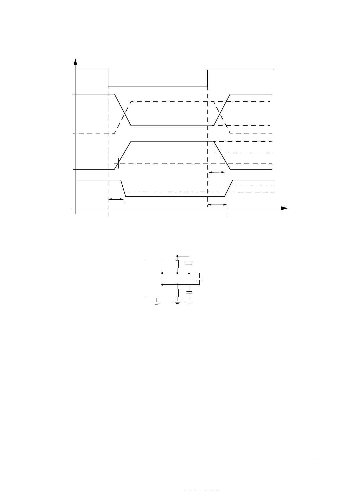
NOTE 1: Dominant to recessive slew rate is dependant upon the bus load characteristics.
NOTE 2: AC Characteristics measured according to schematic figure 3.
t
TX,e
10 60 us
PC33889 10
For More Information On This Product,
Go to: www.freescale.com
Freescale Semiconductor, Inc.
Figure 3. Device Signal W aveforms
PC33889
DEVICE DESCRIPTION
Tx high: RECESSIVE Bit
V
TX
Tx low: DOMINANT Bit
CANL
CANH
V
diff
nc...
I
V
RX
t
onRX
V
th(rd)
Tx high: RECESSIVE Bit
V
th(dr)
t
offTX
t
offRX
5V
3.6V
1.4V
0V
2.2V
0.7V
-2.9V
-5V
0.7V
0.3V
CC
CC
t
DOMINANT Bit RECESSIVE BitRECESSIVE Bit
cale Semiconductor,
Frees
Figure 4. T est Circuit for AC Characteri stics
VDD
R
C
CANL
C
CANH
R
C
R = 100ohms
C = 1nF
PC33889 11
For More Information On This Product,
Go to: www.freescale.com

Freescale Semiconductor, Inc.
PC33889
DEVICE DESCRIPTION
4 DEVICE DESCRIPTION
Introduction:
The MC33889 is a n integrated circuit dedi cated to au tomotive ap plications. It includes th e followin g functions :
- One full protected voltage reg ulator with 200mA tot al output current capa bility .
- Driver for external path tran sistor for V2 regulator func tion.
- Reset, programmable watchdog function
- Four operational modes
- Wake up capabi lities: Force d wake up , cyclic sen se and wa ke up inpu ts, CAN an d SPI
- Can low speed fault toleran t physical in terface, com patible w ith Motorol a MC33388D .
4.1 Device Supply
The device is supplie d fro m th e ba ttery li ne th roug h th e Vsu p pi n. An exte rna l di ode is re quired to protect against negative
transients and rev erse battery . It can operate from 4.5V and under the j ump start condi tion at 27V DC. This pin s ustains sta ndard
automotive volt age conditions s uch as load dump at 40V . When Vsu p falls below 3V ty pical the MC33889 d etects it and sto re the
information into the SPI registe r , in a bit c alled “BATFAIL”. Thi s detection is available in all oper ation modes .
4.2 Vdd1 Voltage Regulator
Vdd1 Regulator is a 5V output voltage with total current capability of 200mA. It includes a voltage monitoring circuitry
associated with a reset function. The Vdd1 regulator is fully protected against over current, short-circuit and has over
temperature detection warning flags and shut down with hysteresis .
nc...
I
cale Semiconductor,
Frees
4.3 V2 regulator
V2 Regulator circuitry i s designe d to dr ive an external p ath tra nsis tor in orde r to incre ase ou tput cur rent f lexib ility. Two pins
are used: V2 and V2 ctrl. Outpu t voltage is 5V and is real ized by a tracking function of the Vdd1 regulator . Recommended bal last
transistor is MJD32C. Other transistor might be used, however depending upon PNP gain an external resistor capacitor network
might be connected between emitter and base of PNP. The use of external ballast is optional (refer to simplified typical
application). S t ate of V2 is reported into IOR register (if V2 is bel ow 4.5V typ ical in ca se of over load or short circuit).
4.4 HS1 Vbat Switch Output
HS1 output is a 2 ohms typic al switch from Vsup pin. It allows th e supply of exter nal switches an d their associated pull up or
pull down circuitry, in conjunction with the wake up input pins for example. Output current is limited to 200mA and HS1 is
protected against short-c ircuit and has an over te mperat ure shut do wn (reporte d in IOR reg ister). H S1 out put is con trolled from
the internal register and SPI. It can be activated at regular intervals in sleep mode thanks to internal timer. It can also be
permanently turned on in no rmal or st and-by modes to driv e external lo ads such as rel ays or suppl y periphera l compone nts. In
case of inducti ve load drive external cl amp circuitry must be added.
4.5 Functional Modes
The device has fou r mo des of o pera tio n, s tand-by, normal, st op a nd s le ep m od es. All m od es are c on trol led by the SPI. An
additional tempora ry mode cal led “normal requ est mode” is automati cally acces sed by the d evice (refer to st ate mac hine) after
wake up event s. Special m ode and co nfiguration a re possible fo r software a pplication debug and fl ash memory p rogramming.
4.5.1 Normal mode:
In this mode both regul ators are ON and thi s correspo nds to the normal applic ation o peratio n. All func tions are avai lable in
this mode (watchdog, wake up input reading through SPI, HS1 activation, CAN communication). The software watchdog is
running and must be periodical ly cleared thro ugh SPI.
4.5.2 Standby mode:
Only the regulator 1 is ON. Regulato r 2 is turned OFF by disabli ng the V2 ctrl pin. The CAN ce ll is not available, as powered
from V2, other functio ns are avai lable: wake u p input read ing through SPI , HS1 activati on. The watch dog is runni ng.
4.5.3 Sleep mode:
Regulators 1 and 2 are O FF. In this mode, the M CU is not powered. In this mode, th e device can be aw akened in ternally by
cyclic sense via the wake up inputs pins and HS1 output, from the forced wake function, the CAN physical interface, and SPI
(CSB pin).
4.5.4 Stop mode
Regulator 2 is turned OFF by disabling the V2 ctrl pin. The regulator 1 is activated in a special low power mode which allow to
deliver 2 mA. The obj ectiv e is to maint ain the MC U of the appl icati on sup plied wh ile it i s turne d into p ower s avin g cond ition (i.e
stop or wait mode ).
Stop mo de is ente red through SPI. S top mode is d edicated to power the M icrocon troller wh en it is in lo w power mode (sto p,
pseudo stop, wa it etc .). In th ese mode the MCU supply current is less than 1m A. T he MCU c an res t art its software application
very quickly, without the complete po wer up and reset sequenc e.
When the application is in stop mode (both MCU and SBC), the applicati on can wake up from the SBC side (ex cyclic se nse,
forced wake up, CAN message, wake up inputs) or the MCU side (key wake up etc.).
When St op mode is selected by SPI, stop mode beco mes act ive 20us after end of S PI message. The “go to s top” instruc tion
must be the last i nstruction e xecuted by the MCU before going to lo w power mod e.
PC33889 12
For More Information On This Product,
Go to: www.freescale.com

Freescale Semiconductor, Inc.
In stop mode the Software watchdog can be “running” or “not running” depending upon selection by SPI. Refer to SPI
description, RCR register bit WDSTOP. If W/D is enabled the SBC must be wake up before W/D time expired, otherwise a reset
is generated. In stop mode, SBC wake up cap ability are identica l as in sleep mode.
4.5.4.1 Stop mode: wake up from SBC side, INT pin activation:
When application is in stop mode, it ca n wake up from the SB C side. When a wake up is detected by t he SBC (ex CAN, W ake
up input, forced wak e up etc.) th e SBC turns i tse lf into Norma l request m ode and activ ated the Vdd1 ma in regul ator. When the
main regulator is fully active, then the wake up is signalled to the MCU through the INT pin. INT pin is pulled low for 10us and
then returns high. Wake up event ca n be read thr ough the SPI registers.
4.5.4.2 Stop mode: wake up from MCU side:
When application is in stop mode, the wake up event may com e to the MCU. In thi s case the MCU has to signa l to the SBC
that it has to go into Normal mod e in order for the Vdd1 regulat or to be able to deliver full cu rrent capabili ty . This is done by a low
to high transition of the CSB pin. CSB pin low to high activation has to be done as soon as possible after the MCU. The SBC
generates a puls e at INTB pi n. Alternative ly the L0 a nd L1 input s can al so be used as wake up from stop m ode.
4.5.4.3 Stop mode current monitoring
If the current in stop mode exceed the Idd1s-wu threshold, the SBC jumps into Normal request mode, activated the Vdd1
main regulator and g enerate and interrupt to th e MCU. This interrupt is no t maskable an d not bit are set into th e INT register.
4.5.4.4 Software watchdog in stop mode:
nc...
I
If watchdog is ena bled (regi ster MCR, b it WDST OP set ), the MCU has to wake up i ndepende ntly of th e SBC be fore the en d
of the SBC watchdog t ime. In o rder to do thi s the MCU has to signal the wake to the SBC through the SP I wake up (CSB pi n low
to high transition to activated SPI wake up). Then the SBC wakes up and jump into the normal request mode. MCU has to
configure the SBC to go to ei ther normal or standby m ode. The MC U can then decide to g o back again to stop mod e.
If no MCU wakes up occurs wit hin the wa tchdog ti ming, the SBC will act ivate the reset pi n and j ump into the normal request
mode. The MCU can then be initialized .
PC33889
DEVICE DESCRIPTION
cale Semiconductor,
Frees
4.5.5 Normal request mode:
This is a temporary mode automatically accessed by the device after a wake up event from sleep or stop mode or after
device power up. In this mode th e Vdd1 re gulator is ON, V2 is of f, the reset p in is high . As soo n as the device e nters the normal
request mode an intern al 350ms timer is st arted. During these 3 50ms the micro cont roller of the applica tion must address ed the
SBC via SPI and configure the watc hdog regis ter (TIM1 registe r). This is the c ondition for t he SBC to leave the Normal reques t
Mode and enter the Normal mode and to set the watchdog timer according to configuration done during the Normal Request
mode.
“BATFAIL flag” is a bit which is triggered when Vsup is below 3V. This bit is set into the MCR register. It is reset by MCR
register read.
4.6 Internal Clock
The device has an internal clock use d to generate all timing s (reset, wa tchdog, cy clic wake u p, filtering time etc....).
4.7 Reset pin
A reset output is av ailable in o rder to reset the microcontro ller . The reset cause a re:
- Vdd1 falling out of range: if Vdd1 fall b elow the re set thresh old (p arameter
to nominal volt age.
- Power on reset: at device power on or at device wake up from slee p mode, the res et is mainta ined low un til Vdd1 is withi n
its operation range.
- Watchdog time out: if the watchdog is not cleared the SBC will pull the reset pin low for the duration of the reset duration
(parameter: reset-dur).
time
For debug purposes at 25°C, reset pin can be shorted to 5V.
4.8 Software watchdog (selectable window or time out watchdog)
Software watchdog is used in the SBC normal and stand-by modes for the MCU monitoring. The watchdog can be either
window or time out. This is select able by SPI (register TIM, bit WDW). Default is window watchdog. The period for the watchdog
is selectab le b y SPI from 5 to 350ms (regi ster TIM, bit s W DT0 and W DT1). When the wind ow wa tchdo g is select ed, the close d
window is the first half o f the selec ted peri od, and the open wind ow is the se cond ha lf of the period. The wa tchdog can on ly be
cleared within the op en window tim e. An attem pt to clear th e watchdog in the clo sed window w ill gene rate a reset. W atchdog is
cleared through SPI by addressing the TIM regi ster .
Refer to” table fo r reset pin operations operation in mode 2.
Rst-th), the reset pin is pu ll low unti l Vdd1 retu rn
4.9 Wake Up capabilities
Several wake-up c apabilities are available for the devic e when it is in sleep or s top mode. Whe n a wake up has occurred , the
wake up event i s stored in to the WUR or CAN regis ters. The M CU can then access to the wake up source. Th e wake u p options
are selectable tro ugh SPI while the device is in normal or st andby mo de and prio r to go to enter low powe r mode (slee p or stop
mode).
PC33889 13
For More Information On This Product,
Go to: www.freescale.com

PC33889
4.9.1 Wake up from wake up inputs (L0, L1) without cyclic sense:
The wake up lines are dedi cated to sense e xternal s witches s tate and if ch anges o ccur to w ake up the MCU (In sleep or stop
modes). The wake u p pins are able t o handle 40V DC. T he interna l thresho ld is 3V typical and thes e input s can be used as inpu t
port expander. The wake up inputs state can be read through SPI (register WUR). L0 has a lower threshold than L1 in order to
allow connection and wake up from a digit al outp ut such as a CAN phys ical interfa ce for inst ance.
4.9.2 Cyclic sense wake up (Cyclic sense timer and wake up inputs L0, L1)
The SBC can wake up upon state change of one of the wake up input lines (L0, L1) while the external pull up or pull down
resistor of the switches associated to the wake up input lines are biased with HS1 Vsup switch. The HS1 switch is activated in
sleep or stop mode from an internal ti mer. Cyclic sense and Forced wake up are exclusi ve. If Cycli c Sense is ena bled the for ced
wake up can not be enabled.
4.9.3 Forced wake up
The SBC can wake up automati ca lly after a p re deter mined time spent in sl eep or sto p mode. F orced wake up is enab led by
setting bit FWU in LPC re gister. Cyclic sense and Forc ed w ake up are excl usive. I f Fo rced wa ke up is e nab led th e Cycl ic Se nse
can not be enabled.
4.9.4 CAN wake up
The device can w ake up fro m a CAN mes sage. CAN w ake up ca nnot be dis abled.
4.9.5 SPI wake up
The device can wake up by the CSB pin in sleep or stop mode. Wake up is detected by CSB pin transition from low to high
level. In stop mode this corres pond to the con dition wh ere MCU and SBC are bot h in S top m ode and whe n the applicat ion wake
up events come through the MCU.
nc...
I
4.9.6 System power up
At power up the device automatical ly wakes up.
Freescale Semiconductor, Inc.
4.10 SPI
The complete devic e control as w ell as the st atus repo rt is done th rough a 8 bi ts SPI interfac e. Refer to SPI paragrap h.
4.11 CAN
The device incorporates a low speed fault tolerant CAN physical interface. Speed rate is up to 125kBauds. Its electrical
parameters for th e CANL, CANH , R tl, R th R x and Tx pins are compat ible with t he MC3338 8D.
The state of the C AN interface i s programmable th rough SPI.
4.12 Device power up, SBC wake up
After device or system power up or a wak e up fr om sleep m ode, the SBC ent ers into “reset mod e” then int o “norma l reques t
mode”.
4.13 Battery fall early warning:
This function provides an I nterrupt when the Vsup voltage is belo w 6.1V typical. This interrupt is maskable. An hy st eres is is
included. Operation is only in Normal and S tandby modes. Vbat low st ate reported i n IOR registe r .
4.14 Package and thermal consideration
cale Semiconductor,
Frees
The device is proposed in a standard surface mount SO28 package. In order to improve the thermal performances of the
SO28 package, 8 pins are in ternally connec ted to the l ead frame an d are used for heat transfer t o the prin ted circuit boa rd.
4.15 Table 1: Reset and Wdogb operation
Figure below shows the reset and watchdog output operation. Reset is active at device power up and wake up. Reset is
activated in case of Vdd1 fa ll or w atchdog no t tri ggered. Wdogb o utput is activ e low as soon a s rese t goes l ow an d st ays l ow as
long as the watchd og is not pr operly re-act ivated by SPI .
PC33889 14
For More Information On This Product,
Go to: www.freescale.com

Vdd1
Reset
PC33889
Freescale Semiconductor, Inc.
Figure 5. Reset and Wdogb function dia gram
Watchdog time out
WDOGB
SPI
W/D clear
SPI CSB
The Wdogb output pin is a push pull structure than can drive external component of the application in order for instance to signal MCU wrong operation. Even if it is internally turned on (low sate) the reset pins can be forced to 5V at 25°C only, thanks to
its internal limited current drive capability. Wdogb stays low until the Watchdog register is properly addressed through SPI.
4.16 Debug mode Application hardware and software debug with the SBC.
nc...
I
cale Semiconductor,
When the SBC is mo unted on the sam e printed circuit b oard as the mic ro control ler it supplie s, bo th applicat ion soft ware and
SBC dedicated routine m ust be debug ged. Fol lowing features allo w the u ser to d ebug t he soft ware by a llow ing the possibi lity t o
disable the SBC inte rnal software wa tchdog time r .
4.16.1 Device power up, reset pin connected to Vdd1
At SBC power up, the Vdd1 voltage is provided, but if no SPI communication occurs to configure the device, a reset occurs
every 350ms. In order to allow software debug and avoi d MCU reset the Reset pin can be connected directly to Vdd1 by a jumper .
4.16.2 Debug modes with software watchdog disabled though SPI (Normal Debug, Standby Debug and Stop Debug)
The software watchdog can be disabled through SPI. In order to avoid unwanted watchdog disable and to limit the risk of
disabling the watc hdog during SBC normal ope ration the w atchdog disab le has to b e done with th e followin g sequence :
Step 1) Power down the SBC
Step 2) Po wer up the SBC (The BA TFAIL bit is set, and the SBC enters nor mal request mode)
Step 3) Write to TIM1 register to allow SBC to enter Normal mode
Step 4) W rite to MCR register wi th data 0 000 (this en ables the debu g mode). (Com plete SPI byte : 000 1 0000 )
Step 5) W rite to MCR register n ormal debug (0001 x101 ), standby d ebug (0001 x 1 10) or Stop debug (0001 x111)
While in debug mode, the SBC can be used without having to clear the W/D on a regular basis to facilitate software and
hardware debug.
Step 6) To leave the debug mode, write 000 0 to MCR reg ister .
T o av oid entering de bug mode af ter a power up, first read BATFAIL b it (MCR read) an d write 0000 i nto MCR.
The graph below ill ustrates t he debug mo de entering.
VSup
Watchdog
period
Watchdog register addressed
Figure 6. Debug mode enter
Frees
Vdd1
Batfail
TIM1(step 3)
SPI
MCR(step4)
debug mode
4.16.3 MCU flash programming configuration
In order to allow the p ossi bil ity to download software into the application memory (MCU EEPROM or F las h) t he SBC al lows
the following capabilities: The Vdd1 can be forced by an external power supply to 5V and the reset and Wdogb outputs by
MCR (step5)
MCR (step6)
SPI: read batfail
SBC in debug Mode, no W/D
SBC not in debug Mode and W/D on
PC33889 15
For More Information On This Product,
Go to: www.freescale.com

PC33889
external signal sour ces to zero or 5V and this with out damage. This allow fo r instance to suppl y the complete appli cation board by
external power supp ly and to a pply the co rrect signal to reset pin s.
4.17 Gnd Shift Detection
4.17.1 General
When normally working in two-wire operating mode, the CAN transmission can afford some ground shift between different
nodes without trouble. Nevertheless, in case of bus failure, the transceiver switches to single-wire operation, therefore working
with less noise m argin. The a ffordable ground shif t is decreas ed in this case.
The SBC provides a ground shift de tection for diagn osis purpose. Four gr ound shift le vels are select able and the detec tion is
stored in the IOR re gister whi ch is acces sible via the SPI.
4.17.2 Detection Principle
The gnd shift to detect is s elected via the SPI out of 4 dif ferent v alues (-0.5V, -1V, -1.5V , -2V). At each TX falling edg e (end of
recessive state) CANH voltage is sensed. If it is detected to be below the selected gnd shift threshold, the bit SHIFT is set at 1 in
IOR register . No filter is implemented . Required filtering for reliab le detection should be do ne by software (e.g. several tria ls).
nc...
I
Freescale Semiconductor, Inc.
cale Semiconductor,
Frees
PC33889 16
For More Information On This Product,
Go to: www.freescale.com

Freescale Semiconductor, Inc.
5 TABLE OF OPER ATION
The table below describe the SBC operation modes.
PC33889
Voltage
mode
Normal
Request
Normal
Standby
nc...
I
Stop
Sleep
Regulator
HS1 switch
Vdd1: ON
V2: OFF
HS1: OFF
Vdd1: ON
V2: ON
HS1
controllable
Vdd1: ON
V2: OFF
HS1
controllable
Vdd1: ON
(limited current
capability)
V2: OFF
HS1: OFF or
cyclic
Vdd1: OFF
V2: OFF
HS1 OFF or
cyclic
cale Semiconductor,
Wake up
capabilities
(if enabled)
CAN (always
enable)
SPI and L0,L1
Cyclic sense or
Forced Wake up
CAN (always
enable
SPI and L0,L1
Cyclic sense
Forced Wake up
Tableau 1 : table of operation
Reset pin INT
Low for 1ms, then high term Vbat
If enabled,
Normally high. Active
low if W/D or Vdd1
under voltage occur
Normally high. Active
low if W/D or Vdd1
under voltage occur
Normally high. Active
low if W/D or Vdd1
under voltage occur
Low Not active No Running
signal failure
(Vdd pre
warning temp,
CAN, HS1)
If enabled,
signal failure
(Vdd temp,
HS1)
Signal SBC
wake up
(not maskable)
Software
Watchdog
Running
Running
- Running if
enabled
- Not
Running if
disabled
CAN cell
Term Vbat
Tx/Rx
Rec only
Term Vbat
Tx/Rx
Rec only
Term
Vbat.
Term
Vbat.
Frees
PC33889 17
For More Information On This Product,
Go to: www.freescale.com

PC33889
Freescale Semiconductor, Inc.
SIMPLIFIED ST ATE MACHINE
W/D: timeout OR Vdd1 low
W/D: timeout & Nostop & !BATFAIL
SBC power up
Power
Down
Reset
Reset counter
(1ms) expired
W
/
D
:
t
i
m
e
o
u
t
Vdd1 low OR W/D: time
out 350ms & !Nostop
O
R
V
d
d
1
lo
1
w
(
n
o
t
e
2
)
1
Normal Request
2
Wake up
2
Stop
W/D: timeout OR Vdd1 low
nc...
I
Wake up
(Vdd1 high temperature OR (Vdd1 low > 100ms & Vsup >BFew)) & Nostop & !BATFAIL
SPI: standby &
W/D trigger
(note1)
3
4
op
t
S
:
I
P
S
to high transition
SPI: Stop & CSB
low to high
transition
& C
low
B
S
W/D: Tri gger
Standby
SPI: standby
Normal
1
1
SPI: normal
Nostop & SPI: sleep &
CSB low to high transition
Nostop & SPI:
sleep & CSB low
to high transition
Sleep
cale Semiconductor,
Frees
1 2 3 4
State machine description:
“Nostop” means N osto p bit = 1
“! Nostop” means Nostop bit = 0
“BA TF AI L” mean s Ba tfail bit = 1
“! BATFAIL” means Batfail bit = 0
“Vdd1 over temperature” means Vdd1 thermal shutdown occurs
“Vdd1 low” means Vdd1 below reset threshold
“Vdd1 low > 100ms” m eans Vdd1 below re set threshold for m ore than
100ms
“W/D: T rigg er” me ans TIM 1 regi ster w rite o perat ion.
Vsup>BFew means Vsup > Battery Fall Early W arning (6.1V typ ical)
denotes priority
Behavior at SBC power up
“W/D: time out” means TIM 1 register not written before W/D time out
period expired, or W/D written in incorrect time window if window W/D selected
(except stop mode). In norma l reques t mode ti me out i s 355ms p2.2 (350m s
p3)ms.
“SPI: Sleep” means SPI write command to MCR register, data sleep
“SPI: S top ” mean s SPI w rite c omman d to M CR regi ster, data stop
“SPI: Normal” means SPI write command to MCR register, data normal
“SPI: Standby” means SPI write command to MCR register, data standby
Note 1: these 2 SPI commands mu st be send in this sequence and
consecutively.
Note 2: if W/D activated
PC33889 18
For More Information On This Product,
Go to: www.freescale.com

PC33889
Normal Request
r
e
g
g
i
r
T
:
D
/
W
Normal
Freescale Semiconductor, Inc.
W/D: time out 350 ms
Transitions to enter debug modes
Reset counter
(1ms) expired
SPI: MCR (0000) & Normal Debug
SPI: MCR (0000) & Standby Debug
Reset
Power
Down
Normal Debug
Standby Debug
nc...
I
cale Semiconductor,
Frees
Stop (1)
R
Stop debug
SPI: Stop
Simplified State machine in debug modes
W/D: time out 35 0ms
R
Wake up
R
Sleep
& !BATFA ILNOSTOP
& SPI: Sleep
Wake up
Normal Request
R
p
u
Wake
SPI: standby &
W/D: Trigger
Standby
SPI: standby debug
Standby Debug
SPI: Stop debug &CSB low to
high transition
Reset counter
(1ms) expired
R
R
S
P
I
:
n
o
r
m
a
l
d
E
SPI: Standby debug
SPI: Normal debug
R
Reset
W
/D
:
T
r
i
g
g
e
r
Normal
ug
eb
e
b
u
dby D
an
g
St
:
SPI
E
SPI: Normal Debug
Normal Debug
R
(1) If stop mode entered, it is entered without watchdog, no matter the WDSTOP bit.
(E) debug mode entry point (step 5 of the debug mode entering sequence).
(R) represents transitions to reset mode due to Vdd1 low.
PC33889 19
For More Information On This Product,
Go to: www.freescale.com

Freescale Semiconductor, Inc.
6 TYPICAL APPLICATIONS
PC33889
nc...
I
cale Semiconductor,
Frees
5V
CAN
supply
V2
Vdd1
INTB
WDOGB
Reset
MOSI
SCLK
MISO
CSB
Txd
Rxd
Gnd
5V/200mA
Vbat
Rrth
Rrtl
Vsup
HS1
L0
L1
Rth
CAN H
CAN L
Rtl
Q1
V2CTRL
Vsup monitor
Dual Volt age Regulator
Vdd1 Monitor
HS1 control
Programmable
wake-up input
Low Speed 125Kbit/s
Fault Tolerant CAN
Physical Interface
V2
5V/200mA
Mode control
Oscillator
Interrupt
Watchdog
Reset
SPI Interface
Fig 1: Simplified typical application with ballast transistor
5V/100mA
Vbat
Rrth
Rrtl
Vsup
HS1
L0
L1
Rth
CAN H
CAN L
Rtl
V2CTRL (open)
Vsup monitor
Dual Voltage Regulator
Vdd1 Monitor
HS1 control
Programmable
wake-up input
Low Speed 125Kbit/s
Fault Tolerant CAN
Physical Interface
V2
5V/200mA
Mode control
Oscillator
Interrupt
Watchdog
Reset
SPI Interface
CAN
supply
V2
Vdd1
INTB
WDOGB
Reset
MOSI
SCLK
MISO
CSB
Txd
Rxd
Gnd
5V/100mA
Fig 2: Simplified typical application without ballast transistor
PC33889 20
For More Information On This Product,
Go to: www.freescale.com
Freescale Semiconductor, Inc.
PC33889
7 SPI INTERFACE
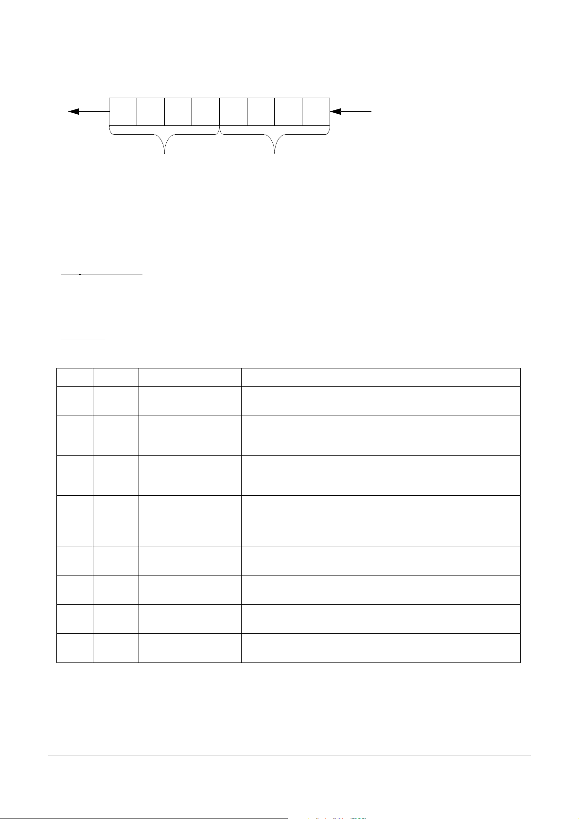
7.1 Data format description
Bit1Bit2Bit3Bit4Bit5Bit6Bit7
Bit0
MISO
The SPI is a 8 bit SPI. Fi rst 3 bits are used to identify the intern al SBC register address , bit 4 is a read/write bit. The last 4 bits
are data send from MCU to SBC or read ba ck from SBC to M CU.
During write opera tion sta te of MISO h as no sign ification.
During read operati on only the last 4 bit s at MISO have a meani ng (content of the acces sed registe r)
Following tabl es describ e the SPI regis ter list, and register bi t meaning.
Registers “reset val ue” is also de scribed, as w ell as the “rese t condition”. re set conditio n is the condi tion which cau se the bit
to be set at the “res et value”.
Possible reset con dition ar e:
Power On Reset: POR
mode transition: NR2R - Normal Request to Reset mode
SBC
NR2N - Normal Requ est to Normal mode
nc...
I
N2R - Normal to Reset mode
STB2R - S tandby to R eset mode
STO2R - Stop to Reset mode
D1D2D3R/WA0A1A2
D0
dataaddress
MOSI
Read operation: R/W bit = 0
Write operation: R/W bit = 1
cale Semiconductor,
Frees
SBC mode:
List of Registers
Name Adress Description Comment and usage
MCR $ 0 0 0 Mode control register
RCR $ 0 0 1 Reset control register
CAN $ 0 1 0 CAN control register
IOR $ 0 1 1 I/O contro l register
WUR $ 1 0 0 Wake up input register
TIM $ 1 0 1 Timing register
LPC $ 1 1 0
RESET - SBC in Reset mode
Low power mode
control register
Write: Control of normal, standby, sleep, and stop modes
Read: BATFAIL flag and other status bits and flags
Write: Configuration of reset voltage level, WD in stop mode, low
power mode selection
Read: CAN wake up event, Tx permanent dominant
Write: CAN module control: Tx/Rx, Rec only, term Vbat, Normal and
extended modes, filter at L0 input.
Read: CAN failure status bits
Write: HS1 (high side switch) control in normal and standby mode.
Gnd shift register level selection
Read: HS1 over temp b it, SHIFT bit (gnd shift above selectio n), Vsu p
below 6.1V, V2 below 4V
Write: Control of wake up input polarity
Read: Wake up input, and real time Lx input state
Write: TIM1, Watchdog timing control, window or Timeout mode.
Write: TIM2, Cyclic sense and force wake up timing selection
Write: HS1 periodic activation in sleep and stop modes
Force wake up control
INTR $ 1 1 1 Interrupt register
Table 7-1.
Write: Interrupt source configuration
Read: INT source
PC33889 21
For More Information On This Product,
Go to: www.freescale.com

7.2 Register description
7.2.1 MCR Register
MCR D3D2D1D0
PC33889
Freescale Semiconductor, Inc.
$000b
Reset 0000
Reset condition
Table 7-2.
Control bits
MCTR2 MCTR1 MCTR0 SBC mode Description
0 0 0 Enter/leave debug mode
nc...
I
001 Normal
0 1 0 Standby
0 1 1 Stop, watchdog off
0 1 1 Stop, watchdog on
100 Sleep
101 Normal
111 Stop
(1): Bit BA TF AIL cannot be set by SPI. BA TF AIL is set when Vsup falls be low 3V .
(2): Watchd og ON or OFF depends up on RCR regis ter bit D3.
(3): Before entering sleep mode, bit NOSTOP in RCR register must be previously set to 1.
W MCTR2 MCTR1 MCTR0
R BATFAIL VDDTEMP GFAIL WDRST
POR, RESET POR, RESET POR, RESET
(2)
(2)
(3)
cale Semiconductor,
Status bit s
Status bit Description
Frees
GFAIL Logic OR of CAN failure, HS1 failure, V2LOW
To enter debug mode, SBC must be
in Normal or Standby mode and
BATFAIL
leave debug mode, BATFAIL must
be at 0.
No watchdog running, debug mode1 1 0 Standby
(1)
must be still at 1. To
BATFAIL Battery fail flag (Vsup<3V)
VDDTEMP Temperature pre-warning on VDD (latched)
WDRST Watchdog reset occurred
PC33889 22
For More Information On This Product,
Go to: www.freescale.com

7.2.2 RCR register
RCR D3 D2 D1 D0
Freescale Semiconductor, Inc.
PC33889
nc...
I
cale Semiconductor,
Frees
$001b
Reset 1 0 0
Reset condition POR, RESET POR, NR2N
Table 7-3.
Control bits
7.2.3 CAN register
Some descriptio n.
CAN D3D2D1D0
$010b
Reset 0000
Reset condition POR, CAN POR, CAN POR, CAN POR, CAN
Table 7-4.
Fault tolerant CAN transceiver st andard modes
The CAN transceiver st andard mod e can be progra mmed by se tting CEXT to 0. The tran sceiver c ell will then be behave as
known from MC3 3388.
WWDSTOP NOSTOP RSTTH
R
Status bit Bit value Description
0 No watchdog in stop mode
WDSTOP
1 Watchdog runs in stop mode
0 Stop mode is default low power mode
NOSTOP
1 Sleep mode is default low power mode
0 Reset threshold 1 selected (typ 4.6V)
RSTTH
1 Reset threshold 2 selected (typ 4.2V)
CANWU 1 Wake from CAN
TXFAILURE 1 Tx permanent dominant (CAN)
W FDIS CEXT CCTR1 CCTR0
R CS3 CS2 CS1 CS0
TXFAILURE CANWU
POR
CEXT CCTR1 CCTR0 Mode
0 0 0 TermVBAT
001
010 RxOnly
011 RxTx
Table 7-5.
Fault tolerant CAN tr ansceiver exten ded modes
PC33889 23
For More Information On This Product,
Go to: www.freescale.com

PC33889
Freescale Semiconductor, Inc.
By setting CEXT to 1 the transceiver cell su pports sub bus com munication.
CEXT CCTR1 CCTR0 Mode
1 0 0 TermVBAT
101 TermVDD
110 RxOnly
111 RxTx
Table 7-6.
FDIS L0 wake input filter (20us typical)
0 Enable (LO wake threshold selectable by WUR register)
1 Disable (L0 wake up threshold is low level only, no matter D0 and D1 bits set in WUR register).
note: if DFIS bit is set to 1, WUR register mus t be read before going into sleep or st op mode in order to clea r the wake up flag.
During read out L 0 must be at high leve l and shoul d stay h igh when ente ring sleep or stop.
nc...
I
Status bit s
CS3 CS2 CS1 CS0 Bus failure # Description
0 0 0 0 no failure
0 0 0 1 1 CANH open wire
0101 5
0110 8, 3a VDD
0 1 1 1 3 VBAT
1 0 0 1 2 CANL open wire
1101 4, 7
1110 9 VDD
cale Semiconductor,
Frees
1 1 1 1 6 VBAT
comments:
CS2 bit at 0 = open failure. CS2 bit at 1 = s hort failure.
(CS3 bit at 0 and (CS1 = 1 or CS2 =1)) = CANH failure. CS3 bit at 1 = CANL failure.
CS1 and CS0 bits : short type fa ilure coding (gnd, Vdd or Vbat).
In case of multi ple failures, th e last failu re is reported .
7.2.4 IOR r egister
Some description.
CANH short circuit to
CANL short circuit to
ground
ground / CANL
IOR D3D2D1D0
$011b
W
R SHIFT HS1OT V2LOW VSUPLOW
Reset
Reset condition
Table 7-7.
HS1ON GSLR1 GSLR0
000
POR, RESET POR, RESET POR, RESET
PC33889 24
For More Information On This Product,
Go to: www.freescale.com

PC33889
Freescale Semiconductor, Inc.
Control bits
GSLR1 GSLR0 typical gnd shift comparator level
0 0 -0.5 V
01 -1 V
1 0 -1.5 V
11 -2 V
T able 7-9. gnd shift selection
nc...
I
HS1ON HS1
0 HS1 switch turn OFF
1 HS1 switch turn ON
Table 7-8.
cale Semiconductor,
Frees
SHIFT state
0 Gnd shift value is lower GSLR1 and GSLR2 selection
1 Gnd shift value is higher GSLR1 and GSLR2 selection
Status bits
Status bit Description
HS1OT (*) High side 1 over temperature
SHIFT gnd shift level selected by GSLR1 and GSLR2 bits is reached
V2LOW V2 below 4V typical
VSUPLOW Vsup below 6.1V typical
(*) Once the HS1 switch has been turne d off because of over temp erature, it can be turned on again by setting the appropriate
control bit to “1”.
7.2.5 WUR register
The local wake-up input s L0 and L1 ca n be us ed in bo th norm al and standby mode as port expander and for waking up the
SBC in sleep o r stop mo de.
WUR D3D2D1D0
$100b
Reset 1 1 1 1
Reset condition POR, NR2R, N2R, STB2R, STO2R
Table 7-10.
W LCTR3 LCTR2 LCTR1 LCTR0
R L1WUb L1WUa L0WUb L0WUa
PC33889 25
For More Information On This Product,
Go to: www.freescale.com

PC33889
Control bits:.
LCTR3 LCTR2 LCTR1 LCTR0 L0 configuration L1 configuration
X X 0 0 inputs disabled
X X 0 1 high level sensitive
X X 1 0 low level sensitive
X X 1 1 both level sensitive
Freescale Semiconductor, Inc.
00XX
0 1 X X high level sensitive
1 0 X X low level sensitive
1 1 X X both level sensitive
Table 7-11.
Status bits:
nc...
I
L0WUb L0WUa
00 0
11 0
01 1
L1WUb L1WUa Description
00
cale Semiconductor,
11
FDIS bit in
CAN register
Description
No wake up occurred at L0 (sleep or stop mode).
Low level state on L0 (standby or normal mode)
Wake up occurred at L0 (sleep or stop mode).
High level state on L0 (standby or normal mode)
Wake up occurred at L0 (sle ep or stop mod e with L0 filter disab le). WUR
must be set to xx00 before sleep or stop mode.
No wake up occurred at L1 (sleep or stop mode).
Low level state on L1 (standby or normal mode)
Wake up occurred at L1 (sleep or stop mode).
High level state on L1 (standby or normal mode)
inputs disabled
Frees
7.2.6 TIM registers
Description: This re gister is s plitted into 2 sub registe rs, TIM1 and TIM2.
TIM1 controls the w atchdog tim ing selecti on as well a s the window or time o ut option. TIM 1 is sele cted when bit D3 is 0.
TIM2 is used to define the timing for the cycl ic sense and forced wake up fun ction. TIM2 is selected wh en bit D3 is 1.
No read operation is allowed for re gisters TIM 1 and TIM2
7.2.7 TIM register
Description.
TIM1 D3 D2 D1 D0
$101b
Table 7-12.
PC33889 26
W 0 WDW WDT1 WDT0
R
For More Information On This Product,
Go to: www.freescale.com

PC33889
Freescale Semiconductor, Inc.
TIM1 D3 D2 D1 D0
Reset
Reset condition POR, RESET POR, RESET POR, RESET
Table 7-12.
Description
WDW WDT1 WDT0 Watc hdo g timi ng [ms]
000 10
001 50
010 100
011 350
100 10
101 50
110 100
nc...
I
jWatchdog ope ration (window and time out)
window closed window open
no watchdog clear allowed
111 350
Table 7-13.
for watchdog clear
000
no window watchdog
window watchdog enabled
(window lenght is half the
watchdog timing)
window open
for watchdog clear
WD timing * 50%
(WD timing selected by TIM 2 bit WDW=1)
7.2.8 TIM2 register
The purpose of TIM2 register is to select an appropriate timing for sensing the wake-up circuitry or cyclically supplying
devices by switching on or off HS1
cale Semiconductor,
TIM2 D3 D2 D1 D0
$101b
Frees
Reset 000
Reset con-
dition
Table 7-14.
WD timing * 50%
Watchdog period
(WD timing selected by TIM 2, bit WDW=0)
Window watchdog
W 1 CSP2 CSP1 CSP0
R
POR, RESET POR, RESET POR, RESET
CSP2 CSP1 CSP0 Cyclic sense timing [ms]
Watchdog period
Time out watchdog
000 5
001 10
010 20
Table 7-15.
PC33889 27
For More Information On This Product,
Go to: www.freescale.com

PC33889
Freescale Semiconductor, Inc.
CSP2 CSP1 CSP0 Cyclic sense timing [ms]
011 40
100 75
1 0 1 100
1 1 0 200
1 1 1 400
Table 7-15.
Cyclic sense timing
nc...
I
HS1
Cyclic sense on time
10µs to 20us
7.2.9 LPC register
Description: This re gister contr ols:
- The state of HS1 in stop and sleep mod e (HS1 permane ntly off or HS1 cycli c)
- Enable or Disable the forced wake up func tion (SBC automat ic wake up after ti me spend in sl eep or stop mode, tim e defined
by TIM2 register)
- Enable or disable the sense of the wake up i nputs (Lx ) at sampl ing point of the cyclic sen se period (LX2 HS1 bit).
cale Semiconductor,
Frees
Reset condition
Table 7-16.
LX2HS
1
sample
t
LPC D3 D2 D1 D0
$110b
Reset 0 0 0 0
HS1AUTO Wake-up inputs supplied by HS1 Autotiming HS1
W LX2HS1 FWU IDDS HS1AUTO
R
POR, NR2R, N2R,
STB2R, STO2R
POR, NR2R, N2R,
STB2R, STO2R
POR, NR2R, N2R,
STB2R, STO2R
POR, NR2R, N2R,
STB2R, STO2R
X0
X 1 on, HS1 cyclic, period defined in TIM2 register
0X no
1 X yes, Lx inputs sens ed at sampling point
Table 7-17.
off
PC33889 28
For More Information On This Product,
Go to: www.freescale.com

PC33889
Freescale Semiconductor, Inc.
Bit Description
7.2.10 INTR register
Reset condition POR, RESET POR, RESET POR, RESET POR, RESET
Table 7-18.
nc...
I
Control bits:
When the mask bit has be en set, INTB pin g oes low if the appropriate condi tion occurs.
Status bits:
cale Semiconductor,
FWU
IDDS
INTR D3 D2 D1 D0
W VSUPLOW HS1OT-V2LOW VDDTEMP CANF
$111b
R VSUPLOW HS1OT VDDTEMP CANF
Reset 0 0 0 0
Control bit Description
CANF Mask bit for CAN failures (OR of any CAN failure)
VDDTEMP Mask bit for VDD medium temperature
HS1OT-V2LOW Mask bit for HS1 over temperature OR V2 below 4V
VSUPLOW Mask bit for sup below 6.1V
Status bit Description
VDDTEMP VDD medium temperature
If this bit is set, and the SBC is turned into sleep or stop mode,
the SBC wakes up after the time selected in the TIM2 register
Bit = 0: Idds-wu1 selected (lowest value, typ 3.5mA)
Bit = 1: Idds-wu2 selected (highest value, typ 14mA)
CANF CAN failure
HS1OT HS1 over temperature
Frees
Notes:
If HS1OT-V2LOW interrupt is only selected (only bit D2 set in INTR register), reading INTR register bit D2 leads to two
possibilities:
Bit D2 = 1: INT source is HS1OT
Bit D2 = 0: INT source is V2LOW .
Upon a wake up condition fro m stop mode due to over curren t detection (Idd1s-wu1 or Id d1s-wu2), an INT pulse is ge nerated,
however INTR registe r contain remains a t 0000 (not bi t set into t he INTR register ).
VSUPLOW Vsup below 6.1V typical
PC33889 29
For More Information On This Product,
Go to: www.freescale.com

Freescale Semiconductor, Inc.
PC33889
CASE OUTLINE
nc...
I
cale Semiconductor,
Frees
A
28
E
1
B
D
PIN 1 IDENT
e
B
M
0.025 B
A
C
15
M
M
H
0.25 B
14
A
0.10
A1
SEATING
C
S
S
PLANE
C
NOTES:
1. DIMENSIONS ARE IN MILLIMETERS.
2. INTERPRET DIMENSIONS AND TOLERANCES
PER ASME Y14.5M, 1994.
3. DIMENSIONS D AND E DO NOT INCLUDE MOLD
PROTRUSIONS.
4. MAXIMUM MOLD PROTRUSION 0.015 PER SIDE.
5. DIMENSION B DOES NOT INCLUDE DAMBAR
PROTRUSION. ALLOWABLE DAMBAR
PROTRUSION SHALL BE 0.13 TOTAL IN EXCESS
OF B DIMENSION AT MAXIMUM MATERIAL
CONDITION.
MILLIMETERS
DIM MIN MAX
A 2.35 2.65
A1 0.13 0.29
B 0.35 0.49
C 0.23 0.32
D 17.80 18.05
L
E 7.40 7.60
e 1.27 BSC
H 10.05 10.55
L 0.41 0.90
q
0 8
q
__
CASE 751F–05
ISSUE F
Motorola reserves the right to make chan ges without furth er notice to any product s herein. Mot orola makes no warranty, representation or guarantee regarding the su itability
of its products for any particular purpose, nor does Motoro la assume any liability arising out of the app lication or use of any pr oduct or circuit, and spec ifically disclai ms any and all
liability, including without limitation consequential or incidental damages. “Typical” parameters which m ay be provided in Motorola data sheets and/or specifications can and do
vary in different applications and actual performance may vary over time. All operating parameters, including “Typical” must be validated for each customer application by
customer’s technical experts. Motor ola does not convey any l icense under it s patent rig hts nor the righ ts of others. Mo torola pro ducts are n ot desi gned, intend ed, or autho rized for
use as components in systems intended for surg ical implant into the body, or other applications intended to support or sustain life, or for any applicati on in which th e failure of the
Motorola product could create a situation where personal injury or death may occur. Should Buyer purchase or use Motorola products for any such unintended or unauthorized
application, Buyer shall indemnify and hold Mo torola and its officers, employees, subsidiaries, affiliates, and distributors harmless against all claims, costs, damages, and
expenses, and reasonable attorney fees arising out of, directly or indirectly, any claim of personal injury or death associated with such unintended or un authorized use, even if
such claim alleges that Motoro la w as neglig ent r egar di ng th e desig n or m anuf actur e of the pa rts. Motorola and are registered trademarks of Motor ola, In c. Mot orola , Inc. is
an Equal Employment Oppor tunity/A ffirm ative Actio n Emplo yer .
How to reach us:
USA / EUROPE / Locations Not Listed
P.O. Box 5405, Denver, Colorado 80217. 1-303-675-2140 or 1-800-441-2447 Minami-Azabu, Minato-ku, Tokyo 106-8573 Japan. 81-3-344-3569
Technical Information Center: 1-800-521-6274 ASIA / PACIFIC
2, Dai King Street, Tai Po Industrial Estate, Tai Po, N.T., Hong Kong.
HOME PAGE
: http://www.motorola.com/semiconductors
: Motorola Literature Distribution;
: Motorola Japan Ltd.; SPS, Technical Information Center, 3-20-1,
JAPAN
: Motorola Semiconductors H.K. Ltd.; Silicon Harbour Centre,
852-26668334
For More Information On This Product,
Go to: www.freescale.com
 Loading...