

Page 1
TM
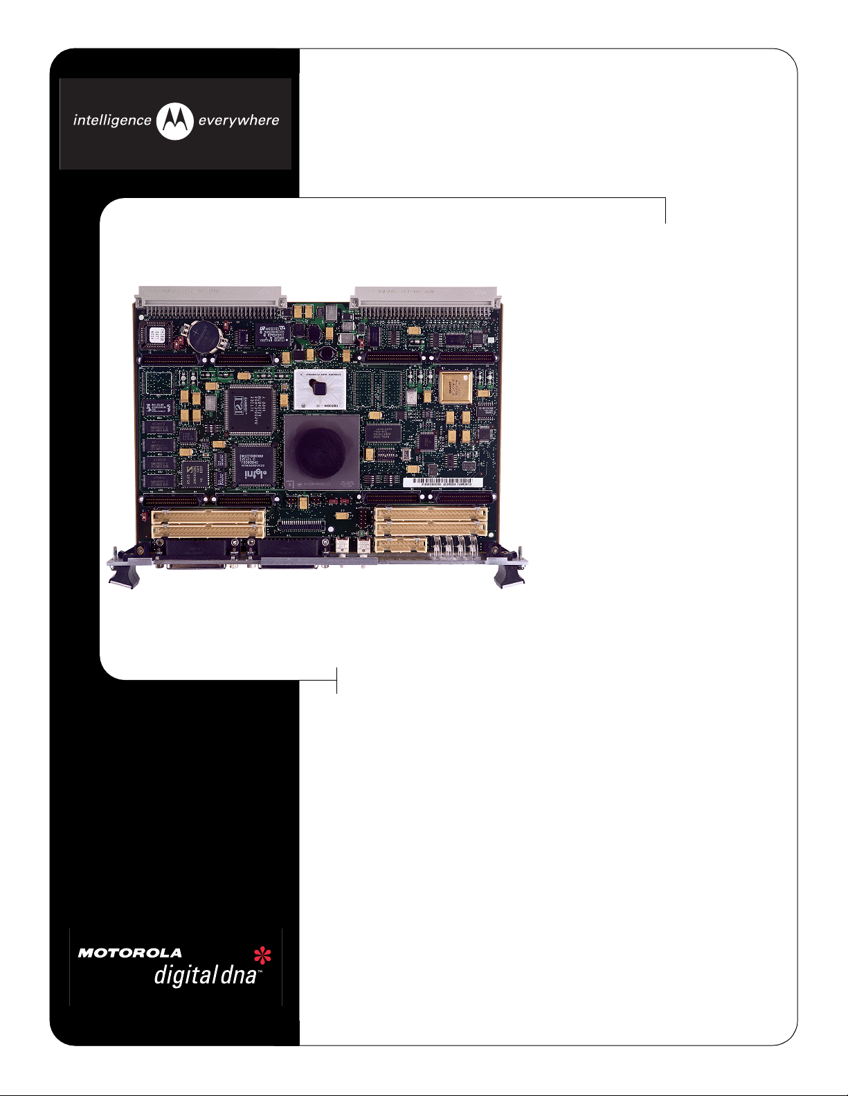
MVME172P4
VME Embedded Controller with 4 IP Slots
♦ Choice of processors: 60 MHz MC68060
enhanced 32-bit microprocessor with
16KB of cache, and MMU and FPU; or 64
MHz MC68LC060 enhanced 32-bit
microprocessor with 16KB of cache and
MMU
♦ A32/D64 VMEbus master/slave interface
with system controller function
♦ 16MB of configurable SDRAM
♦ 512KB of SRAM with battery backup
♦ 2MB Flash memory for on-board monitor/
debugger or user-installed firmware
♦ 8K x 8 NVRAM a nd time-of-day cloc k with
battery backup
♦ Two serial communica tion ports, console
port as EIA-232-D DCE and second port
user configurable for EIA-232-D/EIA-422
(V.36) DTE/DCE
®
♦ Four 16- or two 32-bit IndustryPack
ports with one DMA channel per port
♦ Six 32-bit timers, one watchdog timer
♦ Optional SCSI and Ethernet interfaces
♦ One 32-pin JED EC socket for EPROM
Four-slot IndustryPack logic interface for embedded monitoring and
control applications
The MVME172P4 allows VME embedded controller users to achieve the
price-performance value of RISC architectures while maintaining MC68000
object code compatibilit y. By combining the MC68060 superscalar performance with a wide rang e of optional features an d th e In dus try P ac k in terf ace ,
OEMs can select the exact prod uct for thei r applic ation rather th an payi ng for
unwanted features.
The inclusion of the n ew “Petra” ap plicat ion-spec ific i ntegrate d circuit (ASIC),
which replaces functions formerly implemented in the IP2 chip, MC2 chip,
and MCECC chip, improves the performance of the memory subsystem.
Memory configur ation swit ches e nable th e cust om er to tailo r me mory s ize for
applications requiring smaller memory configurations.
Page 2

VMEbus
A16-32;D08-D64, BLT, UAT, BMLT
Master/Slave
P1
P2
2 Async/Sync Serial
Ports
Optional
VMEchip2
VMEbus interface
16MB
configurable
SDRAM
ECC
MVME172P4 Details
IP A IP B IP C IP D
82596CA
Ethernet
Controller
Petra ASIC
53C710
SCSI
Controller
MVME172P4 Details
Microprocessor Options
The MVME172P4 features the superscalar MC68060 microprocessor which achiev es superb integer and fl oating point
performance from its RI SC hybrid architecture. The object
code compatibility of the MC68060 with earlier generations
allows a significant performance increase while preserving
software investment. For cost-sensitive applications where
floating point performance is not required, the optional
MC68LC060 can be ordered.
VMEbus Interface
VMEbus interface functionality is provided by the VMEchip2
ASIC designed by Motorola. In addition to controlling the sys-
tem’s VMEbus functions, the VMEchip2 includes a local bus
to/from VMEbus DMA controller, VME board support features, as well as globa l control a nd status r egister (G CSR) for
interprocessor communications. The MVME172P4 also provides support for the VME D64 specification within the
VMEbus interface, further enhancing system performance.
Transition Module
An optional MVME712M transition module is available to
support the use of standard I/O connections for the
MVME172P4 series. This module takes the I/O connections
for the peripherals on b oard the MVME17 2P4 se ries fro m the
P2 connection of the module to a transition module that has
industry-standard connections.
MC68060 60 MHz
MC68LC060 64 MHz
2MB Flash
1MB
EPROM
or
I/O Controller
8KB NVRA M
battery-backed
85230 Serial
MK48T58
DB-25 Female
512KB SRAM
battery-backed
IndustryPack Interface
A key feature of the MVME172P4 is the IndustryPack logic
interface. This interface provides a 32-bit data path for the
IndustryPack modules to the local MC68040 bus. IndustryPack modules provide a wide variety of connections to “realworld” applications suc h as I/O, control , interface, analog and
digital functions. Up to four single-wide or two double-wide
IndustryPack modules can be installed on the MVME172P4
and still occupy only one VME slot. As I/O needs change, a
new IndustryPack module can be installed thus preserving
the customer’s overall investment.
Memory Expansion
The MVME172P4 is off ered with a co nfigurable SDRAM. The
size of the memory is determined by switch settings and the
memory devices.
Flexible Design
Because of the flexible nature of the MVME172P4 design,
some features can be removed from the board without affecting hardware or software compatibility. Configur ations are
available without SCSI or Ethernet. IndustryPack and VME
interfaces could al so be removed. Contact yo u local Mo torola
sales representative for more information.
Software Support
Integrated Systems, Inc.:
Microware Systems Corporation:
Microtec:
Wind River Systems, Inc.:
™
pSOS+
OS-9®/OS-9000
™
VRTX32
VxWorks
®
™
Page 3

Specifications
Specifications
Processor
Microprocessor:
Clock Frequenc y:
MC68060 MC68LC060
60 MHz 64 MHz
Memory
Synchronous Dynamic RAM
Capacity:
Read Burst Mode:
Write Burst Mode:
Shared:
16MB
5-2-2-2
4-2-2-2
VMEbus/local bus
Flash
Capacity:
Access Cycles:
2MB
6 read, 7 write
User-Installed ROM
Capacity/Sockets:
1MB/one 32-pin PLCC
Static RAM
Capacity:
Read/Write Burst Mode:
Shared:
Battery Type:
Battery Life
(approximate) :
512KB
5-3-3-3/5-3-3-3
VMEbus/local bus
Lithium
406 days continuous backup at 25° C,
81 days at 70° C
VMEbus ANSI/VITA 1-1994 VME64 (IEEE STD 1014)
DTB Master:
DTB Slave:
Arbiter:
Interrupt Handler:
Interrupt Generator:
System Controller:
Location Monitor:
A16–A32; D08–D64, BLT, UAT + MBLT
A16–A32; D08–D64, BLT, UAT + MBLT
RR/PRI
IRQ 1–7
Any 1 of 7
Yes, jumperable
Four, LMA32
IndustryPack Logic Interface
Data Width:
Interrupts:
Clock Speed:
Module Types:
Connectors:
16/32-bit
Two levels
DMA:
Four channels
8 or 32 MHz
Four single-high, two double-high
Access via four 50-pin planar connectors
SCSI Bus
Controller:
Local Bus DMA:
Asynchronous:
Synchronous:
Connector:
NCR 53C710
Yes, with local bus burst
5MB/s
10MB/s
68-pin micro D high density, available on
P2
Ethernet
Controller:
Local Bus DMA:
Connector:
82596CA
Yes
DB-15, available on P2
TOD Clock
TOD Clock Device:
Replaceable Battery:
MK48T58; 8KB NVRAM
Yes
Counters/Timers
Real-Time Timers/
Counters:
Watchdog Timer:
Six 32-bit programmable, 1 µsec resolution
Time-out generates reset
Serial Ports
Controller:
Number of Ports:
Configuration:
Sync/Async Baud Rate,
bps max.:
Connector:
One 85230
Two
EIA-232-D DCE
38.4K
Front panel DB-25
Hardware Support
Multiprocessing
Hardware Support:
Debug/Monitor
(included):
Transition Module
(optional):
Four mailbox interrupts, RMW, shared
RAM
172Bug, boot and diagnostics
MVME712M
Power Requirements
(with PROM, without IP modules)
Typi cal Maximum
+5V ± 5%
+12V ± 5%
1.5 Amps 1.75 Amps
— 100 mA (max., with off-
board LAN transceiver)
–12V ± 5%
— 100 mA
Board Size
Height:
Depth:
Front Panel Height:
Width:
233.4 mm (9.2 in.)
160.0 mm (6.3 in.)
261.8 mm (10.3 in.)
19.8 mm (0.8 in.)
Demonstrated MTBF
(based on a sample of eight boards in accelerated stress environment)
Mean:
190,509 hours
95% Confidence:
107,681 hours
Environmental
Operating Nonoperating
Temperature:
Altitude:
Humidity (NC):
Vibration:
0° C to +55° C,
–40° C to +85° C
forced air cooling
5,000 m 15,000 m
5% to 90% 5% to 90%
2 Gs RMS,
20–2000 Hz random
20–2000 Hz random
6 Gs RMS,
Page 4

Electromagnetic Compatibility (EMC)
Intended for use in systems meeting the following regulations:
This product was tested in a representative system to the following standards:
CE Mark per European EMC Directive 89/336/EEC with Amendments; Emissions:
EN55022 Class B; Immunity: EN55024
U.S.:
Canada:
FCC Part 15, Subpart B, Class A (non-residential)
ICES-003, Class A (non-residential)
Safety
All printed wiring boards (PWBs) are manufactured with a flammability rating of 94V -0 by UL
recognized manufacturers.
Ordering Information
Ordering Information
Part Number Description
All models include 16MB SDRAM, 2MB Flash, four IndustryPack DMA ports, two serial
ports, and one SIMM module.
Petra I*
MVME172P-644SE
MVME172P-644L
MVME172P-644LE
*Petra I models are not recommended for new design-ins.
MVME172PA-644SE
MVME172PA-644L
MVME172PA-644LE
MVME172PA-644LSE
Related Products
MVME712M
MVME712P2
SIMM05
SIMM06
SIMM07
SIMM08
SIMM09
Documentation
V172PFXA/IH
V1X2PFXA/PG
V172DIAA/UM
VME712MA/IH2
68KBUG1/D
68KBUG2/D
Documentation is available for on-line viewing and ordering at http://www.motorola.com/
computer/literature.
60 MHz MC68060, SCSI, Ethernet
64 MHz MC68LC060
64 MHz MC68LC060, Ethernet
Petra II
60 MHz MC68060, SCSI, Ethernet
64 MHz MC68LC060
64 MHz MC68LC060, Ethernet
64 MHz MC68LC060, SCSI, Ethernet
Four DB-25 female serial port connectors, Centronics parallel port
connector, DB-15 Ethernet connector, SCSI connector, and P2
adapter
P2 adaptor module from VME backplane to cabling for transition
modules
EIA-232D DTE module (option)
EIA-232D DCE module (factory configuration)
EIA-530 DTE module (option)
EIA-530 DCE module (option)
EIA-485 module (option)
MVME172P4 Installation and Use manual
MVME172P4/162P4 Programmer’s Reference Guide
172Bug Diagnostics User’s Manual
MVME712 Transition Module Installation and Use
68K Debugging Package User’s Manual Part 1
68K Debugging Package User’s Manual Part 2
www.motorola.com/computer
1-800-759-1107
Motorola Computer Group
2900 S. Diablo Way
Tempe, AZ 85282
Regional Sales Offices
North America – Boston
120 Turnpike Rd, 1st Floor
Southborough, MA 01772
603-425-1813
North America – Chicago
1501 Woodfield Road, Suite 110E
Schaumburg, IL 60173
847-576-7237
North America – Dallas
2410 Luna Ro ad, Suite 132
Carrollton, TX 75006
972-277-4600
North America – San Jose
1150 Kifer Road, Suite 100
Sunnyvale, CA 94086
408-991-8642
Asia Pacific and Japan
40/F Nat West Tower
Times Square, 1 Matheson St
Causeway Bay, Hong Kong
852-2966-3210
East Mediterranean
6 Kremenetski Street
Tel Aviv 67899 Israel
972-3-568-4388
Zone Technopolis - Immeuble
THETA 3, avenue du Canada - BP304
Courtaboeuf Cedex, France
D-65203 Wiesbaden, Germany
Ashby Road, Loughborough
France
91958 LES ULIS
+33 (0) 1 64 86 64 24
Germany
Hagenauer Strasse 47
+49 (0) 611-3611 604
Benelux
De Waal 26, 5684 PH Best
PO Box 350, 5680 AJ Best
Netherlands
+31 (0) 4993 61250
Nordic
Dalvagen 2
S-169 56 Solna, Sweden
+46 (0) 8 734 8880
United Kingdom
Leicestershire, LE11 3NU
+44 (0) 1509 634300
Motorola and the stylized M logo are registered trademarks and the Intelligence Everywhere logo, Digital DNA and the Digital DNA logo are trademarks of Motorola, Inc. IndustryPack is a
registered trademark of SBS GreenSpring Modular I/O, Inc. LynxOS is a registered trademark of LynuxWorks, Inc. pSOS+ is a trademark of Integrated Systems, Inc. OS-9 is a registered
trademark of Microware Systems Corporation. VRTX32 is a trademark of Microtec. VxWorks is a registered trademark of Wind River Systems, Inc. All other product or service names are the
property of their respective owners.
This datasheet identifies products, th eir specific a tions, an d their ch aracteristics, which may be suitable for certain a pplic ation s. It does no t constitu te an offer to sell or a commitment of pre sent
or future availability, and should not be relied upon to state the terms and conditions, including warranties and disclaimers thereof, on which Motorola may sell products. A prospective buyer
should exercise its own independent jud geme nt to confir m the su itability o f the pr oducts for par ticular applicatio ns. M otorola reserves the right to make changes, without notice, to any products
or information herein which will, in its sole discretion, improve reliability, function, or design. Motorola does not assume any liability arising out of the application or use of any product or circuit
described herein; neither does it convey any license under its patent or other intellectual property rights or under others. This disclaimer extends to any prospective buyer, and it includes
Motorola’s licensee, licensee’s transferees, and licensee’s customers and users. Availability of some of the products and services described herein may be restricted in some locations.
® Reg. U.S. Pat. & Tm. Off. Copyright 2000, 2001 Motorola, Inc. All rights reserved. M172P-D3 10/01
 Loading...