

Page 1

MVME172
VME Embedded Controller
Programmer’s
Reference Guide
VME172A/PG2
Edition of February 1999
Page 2

Notice
While reasonable efforts have been made to assure the accuracy of this document,
Motorola, Inc. a ssumes n o lia bility r esulti ng from any omissio ns in this docu ment, or from
the use of the information ob tained therein. Motorola reserv es the right to r evise this
document and to ma ke c hanges from time to ti me in t he content hereof witho ut o bligation
of Motorola to notify any person of such revision or changes.
No part of this material may be reproduce d or copied in any tangi ble medium, or stored in
a retrieval system, or transmitted in any form, or by any means, radio, electronic,
mechanical, photocopying, recording or facsimile, or otherwise, without the prior written
permission of Motorola, Inc.
It is possible that this pu blicati on ma y cont ain r eferenc e to, or i nformat ion a bout Mot oro la
products (machines and programs), programming, or services that are not announced in
your country. Such refere nces or informat ion must not be construed to mean that Moto rola
intends to announce such Motorola products, programming, or services in your country.
Restricted Rights Legend
If the documentation contained herein is supplied, directly or indirectly, to the U.S.
Government, the following notice shall apply unless otherwise agreed to in writing by
Motorola, Inc.
Use, duplication, or disclosure by the Government is subject to restrictions as set forth in
subparagraph (c)(1)(ii) of the Rights in Technical Data and Computer Software clause at
DFARS 252.227-7013.
Motorola, Inc.
Computer Group
2900 South Diablo Way
Tempe, Arizona 85282
Page 3

Preface
This manual provides board level information and detailed ASIC chip information
including register bit descriptions for the MVME172 Embedded Controller. The
information contained in this manual applies to the following MVME172 models:
MVME172-303
MVME172-213 MVME172-313 MVME172-413 MVME172-513
MVME172-223 MVME172-323
MVME172-233 MVME172-333 MVME172-433
MVME172-243 MVME172-343
MVME172-253 MVME172-353 MVME172-453
MVME172-263 MVME172-363
MVME172-373
This manual is intended for anyone who wants to program these boards in order to design
OEM systems, supply addi ti ona l capability to an exi st ing compa ti bl e s yst em, or work in a
lab environment for experimental purposes.
A basic knowledge of computers and digital logic is assumed.
To use this manual, you should be familiar with the publications listed in Related
Documentation below.
Manual Terminology
Throughout this manual , a convention i s used which pr ecedes dat a and addres s parameters
by a character identifying the numeric format as follows:
$ dollar specifies a hexadecimal character
% percent specifies a binary number
& ampersand specifies a decimal number
For example, “12” is the decimal number twelve, and “$12” is the decimal number
eighteen.
Unless otherwise specified, all address references are in hexadecimal.
An asterisk (*) foll owing the signal name for sign als which are le vel significant denote s that
the signal is true or valid when the signal is low.
An asterisk (*) foll owing the signal name for sign als which are edge significant denote s that
the actions initiated by that signal occur on high to low transition.
Page 4

In this manual, assertion and negation are used to specify forcing a signal to a particular
state. In particular, assertion and assert refer to a signal th at is ac tive or true ; negat ion a nd
negate indicate a sign al tha t is in activ e or fal se. These te rms are u sed i ndepend ently of the
voltage level (high or low) that they represent.
Data and address sizes are defined as follows:
❏ A byte is eight b it s, numbe red 0 through 7, with bi t 0 being the least si gni fi ca nt.
❏ A word is 16 bits, numbered 0 thr ough 15, with bit 0 being the least si gni fi can t.
❏ A longword is 32 bits, numbered 0 through 31, with bit 0 being the least
significant.
The terms contr ol bi t, sta tus bit, true, and false a re use d exte nsivel y in t his do cument. Th e
term control bit is used to describe a bit in a register that can be set and cleared under
software con trol. The term tr ue is used to indicate that a bit is in the state that enables the
function it controls. The term false is used to indi cate that th e bit is in the state tha t disables
the function it cont rols. In all tables, th e terms 0 and 1 are used to descri be the actua l value
that should be writt en to the bi t, or t he val ue tha t it yield s when r ead. The term stat us b it is
used to describe a bit in a register that reflects a specific condition. The status bit can be
read by software to determine operational or exception conditions.
Recent Updates
This edition of the MVME172 VME Embedded Controller Programmer’ s Reference Guid e
incorporates the following changes:
❏ The ‘‘MVME172 Version Register ‘‘ s ectio n has an improved descr iptio n of th e
function of bit V6.
❏ The ‘‘PROM Access Time Cont rol Reg ist er ’’ and ‘‘Flash Access Time Control
Register’’ have clarification relating to bus speed s and access times with the
MVME172’s MC68060 processor.
❏ In accordance with re cent MCG practi ce, the ‘‘Re lated Documentat ion’’ secti on
has been moved from the front of the document to a separate appendix.
Page 5

The computer programs stored in the Read Only Memory of this device contain material
copyrighted by Motorola Inc., first published 1990, and may be used only under a license
such as the License f or Computer Progra ms (Article 14) contained in Moto rola’s T erms and
Conditions of Sale, Rev. 1/79.
This equipment generates , uses, and can radiate elec tro- magneti c
!
WARNING
Motorola and the Motorola symbol are registered trademarks of Motorola, Inc.
All other products ment io ned i n this document are trademarks or re gi st ered trademarks of
their respective holders.
energy. It may cause or be susceptible to electro-magnetic
interference (EMI) if not in stalled and used in a cabinet with
adequate EMI protection.
© Copyright Motorola, Inc. 1999
All Rights Reserved
Printed in the United States of America
February 1999
Page 6

Place holder
Page 7

Contents
CHAPTER 1 Board Description and Memory Maps
Introduction................................................................................................................1-1
Overview....................................................................................................................1-1
Requirements .............................................................................................................1-4
Block Diagrams .........................................................................................................1-5
Functional Description ...............................................................................................1-5
No-VMEbus-Interface Option............................................................................1-5
VMEbus Interface and VMEchip2.....................................................................1-9
Memory Maps............................................................................................................1-9
Local Bus Memory Map.....................................................................................1-9
Normal Address Range................................................................................1-9
Detailed I/O Memory Maps.......................................................................1-21
BBRAM/TOD Clock Memory Map..........................................................1-40
Interrupt Acknowledge Map......................................................................1-46
VMEbus Memory Map.................................... ...... ...........................................1-46
VMEbus Accesses to the Local Bus..........................................................1-47
VMEbus Short I/O Memory Map..............................................................1-47
Software Support Considerations ............................................................................1-47
Interrupts...........................................................................................................1-47
Cache Coherency..............................................................................................1-48
Sources of Local BERR*..................................................................................1-48
Local Bus Time-out...................................................................................1-48
VMEbus Access Time-out.............................. ...... ..... ................................1-49
VMEbus BERR* ................................. ..... .................................................1-49
Local DRAM Parity Error.........................................................................1-49
VMEchip2 .................................................................................................1-49
Bus Error Processing.................................................................................1-49
Description of Error Conditions on the MVME172.........................................1-50
MPU Parity Error.......................................................................................1-50
MPU Off-board Error................................................................................1-51
MPU TEA - Cause Unidentified ...............................................................1-51
MPU Local Bus Time-out.........................................................................1-51
DMAC VMEbus Error ............................. ...... ...... .....................................1-52
DMAC Parity Error................. ...... ...... ......................................................1-52
DMAC Off-board Error.............................................................. ...............1-53
DMAC LTO Error..................................................... ...... ...... ....................1-53
vii
Page 8

DMAC TEA - Cause Unidentified............................................................1-54
LAN Parity Error.......................................................................................1-54
LAN Off-Board Error ...............................................................................1-55
LAN LTO Error ........................................................................................1-55
SCSI Parity Error ......................................................................................1-56
SCSI Off-Board Error...............................................................................1-56
SCSI LTO Error........................................................................................1-56
Example of the Proper Use of Bus Timers.......................................................1-57
MVME172 MC68060 Indivisible Cycles........................................................1-58
Illegal Access to IP Modules from External VMEbus Masters .......................1-59
CHAPTER 2 VMEchip2
Introduction ...............................................................................................................2-1
Summary of Major Features...............................................................................2-1
Functional Blocks......................................................................................................2-4
Local Bus to VMEbus Interface.........................................................................2-4
Local Bus to VMEbus Requester................................................................2-7
VMEbus to Local Bus Interface........................................... ..............................2-9
Local Bus to VMEbus DMA Controller..........................................................2-10
No Address Increment DMA Transfers....................................................2-12
DMAC VMEbus Requester .......................................... ...... ......................2-13
Tick and Watchdog Ti mers............................................................... ..... ...... .....2-14
Prescaler................ ....................................................................................2-14
Tick Timers...............................................................................................2-15
Watchdog Timer........................................................................................2-15
VMEbus Interrupter ............................................ ...... ...... .................................2-16
VMEbus System Controller ................................ ...... .......................................2-17
Arbiter................... ....................................................................................2-17
IACK Daisy-Chain Driver ........................................................................ 2-17
Bus Timer..................................................................................................2-17
Reset Driver ..............................................................................................2-18
Local Bus Interrupter and Interrupt Handler....................................................2-18
Global Control and Status Registers ................................................................2-20
LCSR Programming Model.....................................................................................2-20
Programming the VMEbus Slave Map Decoders............................................2-26
VMEbus Slave Ending Address Register 1 .............................................2-28
VMEbus Slave Starting Address Register 1 ............................................2-28
VMEbus Slave Ending Address Register 2 .............................................2-29
VMEbus Slave Starting Address Register 2 ............................................2-29
VMEbus Slave Address Translation Address Offset Register 1 ..............2-29
viii
Page 9

VMEbus Slave Address Translation Select Register 1 ............................2-30
VMEbus Slave Address Translation Address Offset Register 2...............2-31
VMEbus Slave Address Translation Select Register 2 ............................2-31
VMEbus Slave Write Post and Snoop Control Register 2 ........................2-32
VMEbus Slave Address Modifier Select Register 2.................................2-33
VMEbus Slave Write Post and Snoop Control Register 1 ........................2-35
VMEbus Slave Address Modifier Select Register 1.................................2-36
Programming the Local Bus to VMEbus Map Decoders.................................2-37
Local Bus Slave (VMEbus Master) Ending Address Register 1...............2-39
Local Bus Slave (VMEbus Master) Starting Address Register 1..............2-40
Local Bus Slave (VMEbus Master) Ending Address Register 2...............2-40
Local Bus Slave (VMEbus Master) Starting Address Register 2..............2-40
Local Bus Slave (VMEbus Master) Ending Address Register 3 ..............2-41
Local Bus Slave (VMEbus Master) Starting Address Register 3 .............2-41
Local Bus Slave (VMEbus Master) Ending Address Register 4 ..............2-41
Local Bus Slave (VMEbus Master) Starting Address Register 4 .............2-42
Local Bus Slave (VMEbus Master)
Address Translation Address Register 4 ..........................................2-42
Local Bus Slave (VMEbus Master)
Address Translation Select Register 4 ..............................................2-42
Local Bus Slave (VMEbus Master) Attribute Register 4 .........................2-43
Local Bus Slave (VMEbus Master) Attribute Register 3 .........................2-44
Local Bus Slave (VMEbus Master) Attribute Register 2 .........................2-45
Local Bus Slave (VMEbus Master) Attribute Register 1 .........................2-46
VMEbus Slave GCSR Group Address Register .......................................2-47
VMEbus Slave GCSR Board Address Register .......................................2-48
Local Bus to VMEbus Enable Control Register .......................................2-49
Local Bus to VMEbus I/O Control Register ............................................2-50
ROM Control Register ................................... ...........................................2-51
Programming the VMEchip2 DMA Controller ................................................2-52
DMAC Registers ................................. ......................................................2-53
PROM Decoder, SRAM and DMA Control Register ..............................2-54
Local Bus to VMEbus Requester Control Register ..................................2-55
DMAC Control Register 1 (bits 0-7) ........................................................2-56
DMAC Control Register 2 (bits 8-15) ......................................................2-57
DMAC Control Register 2 (bits 0-7) ........................................................2-59
DMAC Local Bus Address Counter...................................... ..... ...............2-60
DMAC VMEbus Address Counter ...........................................................2-60
DMAC Byte Counter ............................... ...... ...........................................2-61
Table Address Counter .............................................................................2-61
VMEbus Interrupter Control Register ......................................................2-61
VMEbus Interrupter Vector Register .............................................. .........2-63
ix
Page 10

MPU Status and DMA Interrupt Count Register .....................................2-63
DMAC Status Register ............................................................. ................2-64
Programming the Tick and Watchdog Timers..................................................2-65
VMEbus Arbiter Time-out Control Register ...........................................2-65
DMAC Ton/Toff Timers
and VMEbus Global Time-out Control Register..............................2-66
VME Access, Local Bus, and Watchdog Time-out Control Register ......2-67
Prescaler Control Register ........................................................................2-68
Tick Timer 1 Compare Register ...............................................................2-69
Tick Timer 1 Counter ...............................................................................2-69
Tick Timer 2 Compare Register ...............................................................2-70
Tick Timer 2 Counter ...............................................................................2-70
Board Control Register ............................................................................2-71
Watchdog Timer Control Register ...........................................................2-72
Tick Timer 2 Control Register .................................................................2-73
Tick Timer 1 Control Register .................................................................2-74
Prescaler Counter .....................................................................................2-74
Programming the Local Bus Interrupter...........................................................2-75
Local Bus Interrupter Status Register (bits 24-31) ..................................2-78
Local Bus Interrupter Status Register (bits 16-23) ..................................2-79
Local Bus Interrupter Status Register (bits 8-15) ....................................2-80
Local Bus Interrupter Status Register (bits 0-7) ......................................2-81
Local Bus Interrupter Enable Register (bits 24-31) .................................2-82
Local Bus Interrupter Enable Register (bits 16-23) .................................2-83
Local Bus Interrupter Enable Register (bits 8-15) ...................................2-84
Local Bus Interrupter Enable Register (bits 0-7) .....................................2-85
Software Interrupt Set Register (bits 8-15) ..............................................2-86
Interrupt Clear Register (bits 24-31) ........................................................2-86
Interrupt Clear Register (bits 16-23) ........................................................2-87
Interrupt Clear Register (bits 8-15) ..........................................................2-88
Interrupt Level Register 1 (bits 24-31) ..................................................... 2-88
Interrupt Level Register 1 (bits 16-23) ..................................................... 2-89
Interrupt Level Register 1 (bits 8-15) .......................................................2-89
Interrupt Level Register 1 (bits 0-7) .........................................................2-90
Interrupt Level Register 2 (bits 24-31) ..................................................... 2-90
Interrupt Level Register 2 (bits 16-23) ..................................................... 2-91
Interrupt Level Register 2 (bits 8-15) .......................................................2-91
Interrupt Level Register 2 (bits 0-7) .........................................................2-92
Interrupt Level Register 3 (bits 24-31) ..................................................... 2-92
Interrupt Level Register 3 (bits 16-23) ..................................................... 2-93
Interrupt Level Register 3 (bits 8-15) .......................................................2-93
Interrupt Level Register 3 (bits 0-7) .........................................................2-94
x
Page 11

Interrupt Level Register 4 (bits 24-31) .....................................................2-94
Interrupt Level Register 4 (bits 16-23) .....................................................2-95
Interrupt Level Register 4 (bits 8-15) .......................................................2-95
Interrupt Level Register 4 (bits 0-7) .........................................................2-96
Vector Base Register ................................................................................2-96
I/O Control Register 1 ..............................................................................2-97
I/O Control Register 2 ..............................................................................2-98
I/O Control Register 3 ..............................................................................2-98
Miscellaneous Control Register ................................................................2-99
GCSR Programming Model...................................................................................2-101
Programming the GCSR.................................................................................2-103
VMEchip2 Revision Register .................................................................2-105
VMEchip2 ID Register ............................................................................2-105
VMEchip2 LM/SIG Register ..................................................................2-105
VMEchip2 Board Status/Control Register .............................................2-107
General Purpose Register 0 ....................................................................2-108
General Purpose Register 1 ....................................................................2-108
General Purpose Register 2 ....................................................................2-109
General Purpose Register 3 ....................................................................2-109
General Purpose Register 4 ....................................................................2-110
General Purpose Register 5 ....................................................................2-110
CHAPTER 3 MC2 Chip
Introduction................................................................................................................3-1
Summary of Major Features...............................................................................3-1
Functional Description ...............................................................................................3-2
MC2 Chip Initialization......................................................................................3-2
Flash and PROM Interface .................................................................................3-2
BBRAM Interface............................................................. ...... ............................3-3
82596CA LAN Interface ....................................................................................3-3
MPU Port and MPU Channel Attention......................................................3-3
MC68060-Bus Master Support for 82596CA .............................................3-4
LANC Bus Error................................................... .......................................3-4
LANC Interrupt ....................... ...... ..............................................................3-5
53C710 SCSI Controller Interface......................................................................3-5
SRAM Memory Controller.................................................................................3-5
NON-ECC DRAM Memory Controller .............................................................3-5
Z85230 SCC Interface........................................................................................3-6
Tick Timers............................................................ ........................................ .....3-7
Watchdog Timer..................................................................................................3-8
xi
Page 12

Local Bus Timer.................................................................................................3-8
Memory Map of the MC2 Chip Registers.................................................................3-8
Programming Model................................................................................................3-10
MC2 Chip ID Register .....................................................................................3-11
MC2 Chip Revision Register ........................................................................... 3-11
General Control Register .................................................................................3-12
Interrupt Vector Base Register .........................................................................3-13
Programming the Tick Timers..........................................................................3-15
Tick Timer 1 and 2 Compare and Counter Registers................................3-15
LSB Prescaler Count Register........................................................ ...... .....3-17
Prescaler Clock Adjust Register................................................................3-18
Tick Timer 1 and 2 Control Registers.......................................................3-18
Tick Timer Interrupt Control Registers.....................................................3-20
DRAM Parity Error Interrupt Control Register ...............................................3-22
SCC Interrupt Control Register........................................................................3-23
Tick Timer 3 and 4 Control Registers.............................................................. 3-24
DRAM and SRAM Memory Controller Registers...........................................3-25
DRAM Space Base Address Register.......................................................3-25
SRAM Space Base Address Register........................................................3-26
DRAM Space Size Register........ ...... ...... ..................................................3-26
DRAM/SRAM Options Register ..............................................................3-27
SRAM Space Size Register.......................................................................3-29
LANC Error Status Register............................................ ..... ............................3-30
82596CA LANC Interrupt Control Register....................................................3-31
LANC Bus Error Interrupt Control Register....................................................3-32
SCSI Error Status Register...............................................................................3-33
General Purpose Inputs Register........ ...... ........................................................3-33
MVME172 Version Register............................................................................3-35
SCSI Interrupt Control Register.......................................................................3-36
Tick Timer 3 and 4 Compare and Counter Registers.......................................3-37
Bus Clock Register ...........................................................................................3-38
PROM Access Time Control Register .............................................................3-39
Flash Access Time Control Register................................................................3-40
ABORT Switch Interrupt Control Register......................................................3-41
RESET Switch Control Register......................................................................3-42
Watchdog Timer Control Register....................................................................3-43
Access and Watchdog Time Base Select Register............................................3-44
DRAM Control Register ................................................. ..... ............................3-45
MPU Status Register........................................................................................3-46
32-bit Prescaler Count Register........................................................................3-48
xii
Page 13

CHAPTER 4 IP2 Chip
Introduction................................................................................................................4-1
Summary of Major Features...............................................................................4-1
Functional Description ...............................................................................................4-2
General Description............................................................................................4-2
Cache Coherency................................................................................................4-2
Local Bus to IndustryPack DMA Controllers.....................................................4-3
Clocking Environments and Performance..........................................................4-5
Programmable Clock..........................................................................................4-7
Error Reporting...................................................................................................4-7
Error Reporting as a Local Bus Slave .................................................... .....4-7
Error Reporting as a Local Bus Master .......................................................4-7
IndustryPack Error Reporting......................................................................4-8
Interrupts.............................................................................................................4-8
Overall Memory Map ................................................................................................4-9
Programming Model................................................................................................4-10
Chip ID Register...............................................................................................4-17
Chip Revision Register.....................................................................................4-17
Vector Base Register.........................................................................................4-18
IP_a, IP_b, IP_c, IP_d Memory Base Address Registers.................................4-19
IP_a or Double Size IP_ab Memory Base Address Registers ..................4-20
IP_b Memory Base Address Registers......................................................4-20
IP_c or Double Size IP_cd Memory Base Address Registers...................4-21
IP_d Memory Base Address Registers......................................................4-21
IP_a, IP_b, IP_c, IP_d Memory Size Registers................................................4-21
IP_a, IP_b, IP_c, and IP_d; IRQ0 and IRQ1 Interrupt Control Registers........4-23
IP_a, IP_b, IP_c, and IP_d; General Control Registers....................................4-24
IP Clock Register..............................................................................................4-28
DMA Arbitration Control Register...................................................................4-29
IP RESET Register ..........................................................................................4-30
Programming the DMA Controllers.................................................................4-31
DMA Enable Function...............................................................................4-33
DMA Control and Status Register Set Definition.....................................4-33
Programming the Programmable Clock....................................................4-43
Local Bus to IndustryPack Addressing....................................................................4-46
8-Bit Memory Space .........................................................................................4-46
16-Bit Memory Space.......................................................................................4-47
32-Bit Memory Space.......................................................................................4-48
IP_a I/O Space..................................................................................................4-49
IP_ab I/O Space................................................................................................4-50
IP_a ID Space ...................................................................................................4-51
xiii
Page 14

IP to Local Bus Data Routing..................................................................................4-52
Memory Space Accesses...................................................... ...... ...... ................4-52
I/O and ID Space Accesses ..............................................................................4-54
CHAPTER 5 MCECC
Introduction ...............................................................................................................5-1
Features......................................................................................................................5-1
Functional Description ..............................................................................................5-2
General Description............................................................................................5-2
Performance........................................................................................................5-2
Cache Coherency................................................................................................5-3
ECC....................................................................................................................5-4
Cycle Types.................................................................................................5-4
Error Reporting ................................. ..........................................................5-5
Single Bit Error (Cycle Type = Burst Read or Non-Burst Read) ...............5-5
Double Bit Error (Cycle Type = Burst Read or Non-Burst Read)..............5-5
Triple (or Greater) Bit Error
(Cycle Type = Burst Read or Non-Burst Read)..................................5-6
Cycle Type = Burst Write...........................................................................5-6
Single Bit Error (Cycle Type = Non-Burst Write)......................................5-6
Double Bit Error (Cycle Type = Non-Burst Write)....................................5-6
Triple (or Greater) Bit Error (Cycle Type = Non-Burst Write) ..................5-6
Single Bit Error (Cycle Type = Scrub) .......................................................5-6
Double Bit Error (Cycle Type = Scrub)......................................................5-7
Triple (or Greater) Bit Error (Cycle Type = Scrub)....................................5-7
Error Logging.....................................................................................................5-7
Scrub...................................................................................................................5-7
Refresh..................................... ...... .....................................................................5-8
Arbitration.................... ...... ................................................................................5-8
Chip Defaults......................................................................................................5-8
Programming Model..................................................................................................5 -9
Chip ID Register...............................................................................................5-14
Chip Revision Register.....................................................................................5-14
Memory Configuration Register .......................................... ............................5-15
Dummy Register 0............................................................................................5-16
Dummy Register 1............................................................................................5-17
Base Address Register......................................................................................5-17
DRAM Control Register ................................................. ..... ............................5-18
BCLK Frequency Register...............................................................................5-20
Data Control Register.......................................................................................5-21
xiv
Page 15

Scrub Control Register......................................................................................5-23
Scrub Period Register Bits 15-8........................................................................5-24
Scrub Period Register Bits 7-0..........................................................................5-24
Chip Prescaler Counter.....................................................................................5-25
Scrub Time On/Time Off Register....................................................................5-25
Scrub Prescaler Counter (Bits 21-16)...............................................................5-27
Scrub Prescaler Counter (Bits 15-8).................................................................5-28
Scrub Prescaler Counter (Bits 7-0)...................................................................5-28
Scrub Timer Counter (Bits 15-8)......................................................................5-28
Scrub Timer Counter (Bits 7-0)........................................................................5-29
Scrub Address Counter (Bits 26-24).................................................................5-29
Scrub Address Counter (Bits 23-16).................................................................5-30
Scrub Address Counter (Bits 15-8)...................................................................5-30
Scrub Address Counter (Bits 7-4).....................................................................5-31
Error Logger Register....................................................... ................................5-31
Error Address (Bits 31-24)...............................................................................5-32
Error Address (Bits 23-16)...............................................................................5-33
Error Address Bits (15-8).................................................................................5-33
Error Address Bits (7-4)...................................................................................5-33
Error Syndrome Register........... .......................................................................5-34
Defaults Register 1............................................................................................5-34
Defaults Register 2............................................................................................5-36
Initialization......................................................................................................5-37
Syndrome Decode....................................................................................................5-39
APPENDIX A Related Documentation
Motorola Computer Group Documents....................................................................A-1
Literature Updates..............................................................................................A-2
Manufacturers’ Documents.......................................................................................A-2
APPENDIX B Using Interrupts on the MVME172
Introduction...............................................................................................................B-1
VMEchip2 Tick Timer 1 Periodic Interrupt Example..............................................B-1
INDEX
xv
Page 16

FIGURES
Figure 1-1. 200/300-Series MVME172 Block Diagram...........................................1-6
Figure 1-2. 400/500-Series MVME172 Block Diagram ...........................................1-7
Figure 2-1. VMEchip2 Block Diagram.....................................................................2-5
TABLES
Table 1-1. MVME172 Features Summary.................................................................1 -3
Table 1-2. Redundant Functions in the VMEchip2 and MC2 Chip .........................1-8
Table 1-3. 200/300-Series MVME172 Local Bus Memory Map............................1-10
Table 1-4. 400/500-Series MVME172 Local Bus Memory Map............................1-12
Table 1-5. 200/300-Series MVME172 Local I/O Devices Memory Map...............1-14
Table 1-6. 400/500-Series MVME172 Local I/O Devices Memory Map...............1-18
Table 1-7. VMEchip2 Memory Map (Sheet 1 of 3)................................................1-22
Table 1-8. MC2 Chip Register Map........................................................................1-27
Table 1-9. IP2 Chip Overall Memory Map..............................................................1-28
Table 1-10. IP2 Chip Memory Map - Control and Status Registers .......................1-29
Table 1-11. MCECC Internal Register Memory Map ............................................1-35
Table 1-12. Z85230 SCC Register Addresses .........................................................1-37
T ab le 1-13. 82596CA Ethernet LAN Memory Map.......................... ......................1-38
Table 1-14. 53C710 SCSI Memory Map ...............................................................1-39
Table 1-15. MK48T58 BBRAM/TOD Clock Memory Map...................................1-40
T ab le 1-16. BBRAM Configuration Area Memory Map .......................................1-41
Table 1-17. TOD Clock Memory Map ....................................................................1-42
Table 2-1. VMEchip2 Memory Map - LCSR Summary (Sheet 1 of 2) ..................2-22
Table 2-2. DMAC Command Table Format............................................................2-53
Table 2-3. Local Bus Interrupter Summary ............................................................2-76
Table 2-4. VMEchip2 Memory Map (GCSR Summary) ......................................2-104
Table 3-1. DRAM Performance.................................................................................3 -6
Table 3-2. MC2 Chip Register Map .........................................................................3-9
Table 3-3. Interrupt Vector Base Register Encoding and Priority...........................3-14
Table 3-4. DRAM Size Control Bit Encoding.........................................................3-27
Table 3-5. DRAM Size Control Bit Encoding.........................................................3-28
Table 3-6. SRAM Size Control Bit Encoding .........................................................3-28
Table 3-7. SRAM Size Control Bit Encoding .........................................................3-29
Table 4-1. IP2 Chip Clock Cycles.............................................................................4-6
Table 4-2. IP2 Chip Overall Memory Map ...............................................................4-9
Table 4-3. IP2 Chip Memory Map - Control and Status Registers .........................4-11
xvi
Page 17

Table 5-1. MCECC Specifications.............................................................................5-3
Table 5-2. MCECC Internal Register Memory Map, Part 1....................................5-10
Table 5-3. MCECC Internal Register Memory Map, Part 2 ...................................5-12
T ab le A-1. Motorola Computer Gr oup Documents..................................................A-1
Table A-2. Manufacturers’ Documents....................................................................A-2
xvii
Page 18

xviii
Page 19

1Board Description
Introduction
This manual provides programming information for the MVME172
Embedded Controller. Ex tensive programming in formation is provide d for
the Application-Specific Integrated Circuit (ASIC) devices used on the
board. Reference information is included for the Large Scale Integration
(LSI) devices us ed on the boa rd and sourc es for a dditional information are
provided.
This chapter briefly describes the board level hardware features of the
MVME172 Embedded Controller. The chapter begins with a board level
overview and featur es l ist. Memory maps are next, and the chapter close s
with some general software considerations such as cache coherency,
interrupts, and bus errors.
All programmable registers in the MVME172 that reside in ASICs are
covered in the chapters on those ASICs. Chapte r 2 cover s the VMEchi p2,
Chapter 3 covers the MC2 chip, an d Chapter 4 covers the IP2 chip. Chapter
5 covers the MCECC chip, used only on 200/300-Series MVME172.
Appendix A describes using interrupts. For those interested in
programmable register bit definitions and less interested in hardware
functionality, focus on Chapters 2, 3, 4, and 5. In some cases, however,
Chapter 1 gives related background information.
and Memory Maps
1
Overview
The MVME172 is based on the MC68060 or MC68LC060
microprocessor. The MVME172 is available in various versions with the
features listed in Table 1-1 on page 1-3. A “No VMEbus” option is also
available.
The I/O connection fo r the 200/300-Seri es MVME172 is provided thr ough
four RJ-45 front panel connectors.
1-1
Page 20

1
Board Description and Memory Maps
The I/O connection for t he 4 00/500-Series serial ports is p rovided by two
DB-25 front panel I/O connectors. The I/O is connected to t he VMEbus P2
connector. The main boar d is connect ed through a P2 t ransiti on board and
cables to transition boards. The Series 400/500 MVME172 supports the
transition boards MVME712-12, MVME712-13, MVME712M,
MVME712A, MVME712AM, and MVME712B (referred to in this
manual as MVME712x, unless separately specified). These transition
boards provide configuration headers, serial port drivers and industry
standard connectors for the I/O devices. The MVME712 series transition
boards were designed to support the MVME167 boards, but can be used
on the MVME172 by following some special precautions. (Refer to the
section on the Serial Communications Interface in the MVME172
installation and use manual furnished with your 400/500-Series
MVME172, for more informat ion.)
The VMEbus interface is provi ded by an ASIC called th e VMEchip2. The
VMEchip2 includes two tick timers, a watchdo g timer, programmable map
decoders for the master and sl ave inter faces, and a VMEbus to/ from loc al
bus DMA controller, a VMEbus to/ from local bus non-DMA programmed
access interface, a VMEbus interrupter, a VMEbus system controller, a
VMEbus interrupt handler, and a VMEbus requester.
Processor-to-VMEbus tra nsfers can be D8, D16, or D32. VMEchip2 DMA
transfers to the VMEbus, however, can be D16, D32, D16/BLT, D32/BLT,
or D64/MBLT.
The MC2 chip ASIC provides four tick timers, the interface to the LAN
chip, SCSI chip, seri al port chip , BBRAM, the progra mmable interfac e for
the DRAM and/or SRAM mezzanine board, and Flash write enable.
The IndustryPack Interface Controller (IP2 chip) ASIC provides control
and status information, including DMA control, for up to four single size
IndustryPacks (IPs) or up to two double size IPs that can be plugged into
the MVME172 main module.
1-2 Computer Group Literature Center Web Site
Page 21
Overview
The MCECC chip Memory Controller ASIC on the 200/300-Series
MVME172 provides the programmable interface for the ECC-protected
16 MB DRAM mezzanine board.
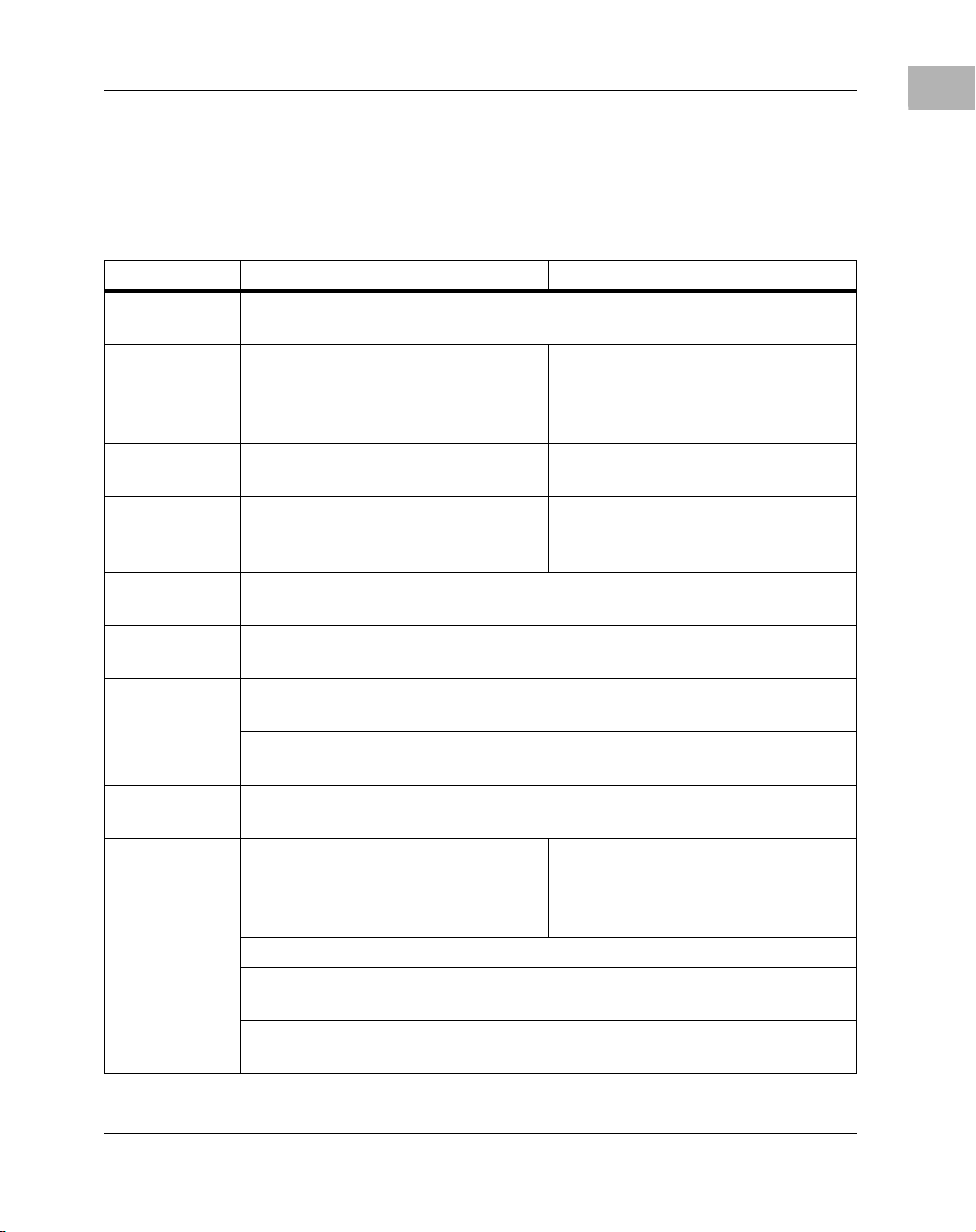
Table 1-1. MVME172 Features Summary
Feature 200/300-Series 400/500-Series
Processor 6
0 MHz 32-bit MC68060 microprocessor, or 64 MHz 32-bit
MC68LC060 microprocessor
DRAM 4MB, 8 MB, or 16 MB of shared
DRAM with parity protection on a
mezzanine module, or up to 64 MB of
ECC-protected DRAM
SRAM 128 K
B of SRAM with battery
4MB, 8 MB, or 16 MB of shared
DRAM with no protection
512KB of SRAM with battery backup
backup
PROM/
EPROM
Sockets
Flash One Intel 28F016SA 2M x 8 Flash memory device (2MB Flash memory
NVRAM and
TOD
Timers Four 32-bit Tick Timers and Watchdog Timer (in the MC2 Chip ASIC) for
Software
Interrupts
I/O Four serial ports, both EIA-232-D RJ-45Tw
Two JEDEC standard 32-p in DIP
PROM sockets
total) with write protection (optional)
8K by 8 Non-Volatile RAM (NVRAM) and Time-of-Day (TOD) clock with
battery backup
periodic interrupts
Two 32-bit Tick Timers and Watchdog Timer in the VMEchip2 ASIC) for
periodic interrupts
Eight software interrupts (for MVME172 versions that have the VMEchip2)
Serial port controller
Optional Small Computer Systems Interface (SCSI) bus interface with 32-bit
local bus burst Direct Memory Access (DMA) (NCR 53C710 controller)
Optional LAN Ethernet transceiver interface with 32- bit lo cal b us DMA (In ter
82596CA controller)
s (Zilog Z85230)
ne JEDEC standard 32-pin
O
PLCC EPROM socket (EPROMs
may
be shipped separately)
o serial ports; one EIA-232-D
DCE, one EIA-232-D DCE/DTE or
EIA-530 DCE/DTE or EIA-42
DCE/DTE or EIA-485
1
http://www.mcg.mot.com/literature 1-3
Page 22

1
Board Description and Memory Maps
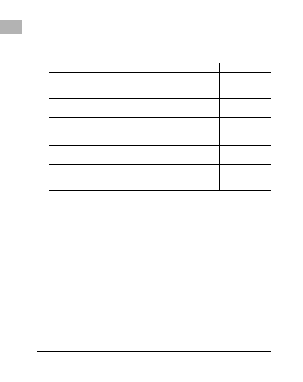
Table 1-1. MVME172 Features Summary
Feature 200/300-Series 400/500-Series
Two MVIP IndustryPack
interfaces with DMA
VMEbus
interface
(boards may be
special ordered
without the
VMEbus
interface)
Switches Two pushbutton switches
Light-Emitting
Diodes (LEDs)
VMEbus system controller functions
VMEbus interface to local bus (A24/A32,
D8/D16/D32 (D8/D16/D32/D64 BLT) (BLT = Block Transfer)
Local bus to VMEbus interface (A16/A24/A32, D8/D16/D32)
VMEbus interrupter
VMEbus interrupt handler
Global CSR for interprocessor communications
DMA for fast local memory - VMEbus transfers (A16/A24/A32, D16/D32
(D16/D32/D64 BLT)
Four LEDs: FAIL, RUN, SCON,
FUSES (LAN power)
(ABORT and RESET)
Four MVIP IndustryPack
interfaces with DMA
Eight LEDs: FAIL, STAT, RUN,
SCON, LAN, FUSE (LAN power),
SCSI, and VME
Requirements
These boards are desi gned to conform t o the requirements of the followin g
documents:
❏ VMEbus Specification (IEEE 1014-87)
❏ EIA-232-D Serial Interface Specification, EIA
❏ SCSI Specification, ANSI
❏ IndustryPack Specification, GreenSpring
1-4 Computer Group Literature Center Web Site
Page 23

Block Diagrams
Figure 1-2 on page 1-7 is a general block diagram of the 200/300-Series
MVME172. Figure 1-2 on page 1-7 is a general block diagram of the
400/500-Series MVME172.
Functional Description
This section covers only a few specific features of the MVME172.
A complete functional description of the major blocks of the MVME172
Embedded Controller is provided in your MVME172 installation and use
manual.
No-VMEbus-Interface Option
The MVME172 can be operated as an embedded controller without the
VMEbus interface. For this option, the VMEchip2 and the VMEbus
buffers are not populat ed. Also, the bu s grant daisy ch ain an d the i nterrupt
acknowledge daisy chain have zero-ohm bypass resistors installed.
Block Diagrams
1
To support this fea ture, certain l ogic in the VMEchip2 h as been duplic ated
in the MC2 chip. Table 1-2 on page 1-8 defines the location of the
redundant logic. This logic is inhibited in the MC2 chip if the VMEchip2
is present. The enables for these functions are controlled by software and
MC2 chip hardware initialization.
Note that an MVME172 ordered witho ut the VMEbus i nterface is shipped
with Flash memory blank (the factory uses the VMEbus to program the
Flash memory with debugger code). To use the 172Bug package,
MVME172Bug, in such models, be sure that the General Purpose
Readable Jumpers Header is configured for the EPROM memory map.
Refer to Chapters 3 and 4 of your MVME172 installat ion and use manual
for further details.
http://www.mcg.mot.com/literature 1-5
Page 24

1
Board Description and Memory Maps
4 Serial Ports
Optional
RJ-45 Front
Panel
SCSI
Ethernet
2MB
Flash
Optional
EIA-232
Transceivers
Connector
Peripherals
Panel SCSI
68-pin Front
Panel
Connector
Transceiver
DB-15 Front
Serial
Dual 85230
I/O Controllers
MC2 chip
Sockets
EPROM
Two 32-p in
SCSI
53C710
Coprocessor
Ethernet
Controller
i82596CA
M48T58
Battery Backed
8KB RAM/Clock
128KB SRAM
Memory Array
ECC DRAM
Memory Array
4,8,16,32,64MB
Array
DRAM Memory
4,8,16MB Parity
21009702
w/Battery
Configuration Dependent
A32/D32
I/O
2 Channels
IndustryPack
Optional
VMEbus
Master/Slave
IP2
Interface
IndustryPack
MPU
Optional
MC68LC060
VMEbus
Interface
VMEchip2
MC68060
A32/24:D64/32/16/08
Figure 1-1. 200/300-Series MVME172 Block Diagram
1-6 Computer Group Literature Center Web Site
Page 25

Functional Description
1
2MB
Flash
Optional
or
Via P2 and
2 Serial Ports
Transition Module
DB-25 Front Panel
SCSI
Optional
Ethernet
Peripherals
Transceiver
Via P2 and
connections are
Via P2 and
connections are
EIA-232
Transceivers
Transition Modules
Transition Modules
Serial
Dual 85230
I/O Controllers
MC2 chip
Socket
1 PLCC
SCSI
53C710
Coprocessor
Ethernet
Controller
i82596CA
M48T58
Battery Backed
8KB RAM/Clock
512KB SRAM
Memory Array
Array
DRAM Memory
4,8,16MB Parity
2038 9706
w/Battery
Configuration Dependent
A32/D32
Optional
I/O
4 Channels
IndustryPack
VMEbus
Master/Slave
A32/24:D64/32/16/08
IP2
Interface
IndustryPack
MPU
Optional
MC68LC060
VMEbus
Interface
VMEchip2
MC68060
Figure 1-2. 400/500-Series MVME172 Block Diagram
http://www.mcg.mot.com/literature 1-7
Page 26
1
Board Description and Memory Maps
Table 1-2. Redundant Functions in the VMEchip2 and MC2 Chip
VMEchip2 MC2 Chip
Address Bit # Address Bit #
$FFF40060 28 - 24 $FFF42044 28 - 24 1,5
$FFF40060 22 -
19,17,16
$FFF4004C 13 - 8 $FFF42044 13 - 8 3,5
$FFF40048 7 $FFF42048 8 4
$FFF40048 9 $FFF42048 9 4,5
$FFF40048 10 $FFF42048 10 4,5
$FFF40048 11 $FFF42048 11 4,5
$FFF40064 31 - 0 $FFF4204C 31 - 0 8
$FF800000-$FFBFFFFF 31 - 0 $FF800000-
$FFE00000-$FFEFFFFF 31 - 0 Programmable 31 - 0 7
$FFF42044 22 -
19,17,16
$FFF42040 6 - 0 6
31 - 0 7
$FFBFFFFF
Notes
2,5
Notes 1. RESET switch control.
2. Watchdog ti mer control.
3. Access and watchdog timer parameters.
4. MPU TEA (bus error) status
5. Bit numbering for VMEchip2 and MC2 chip has a one-toone correspondence.
ABORT switch interrupt control. Implemented also in the
6.
VMEchip2, but with a di ffer ent bit organi zati on (r efer to the
VMEchip2 description i n Ch apt er 2) . I n the MVME172, the
ABORT switch is wired to the MC2 chip, not the VMEchip2.
7. The SRAM and PROM decoder in the VMEchip2 (versi on
2) must be disabled by software before any accesses are made
to these address spaces.
8. 32-bit prescaler. The prescaler can also be accessed at
$FFF40064 when the optional VMEbus is not enabled.
1-8 Computer Group Literature Center Web Site
Page 27

VMEbus Interface and VMEchip2
The local bus to VMEb us interf ace an d the VMEbus to local b us interf ace
are provided by the VMEchip2. The VMEchip2 can also provide the
VMEbus system controller functions. Refe r to the VMEchip2 i n Chapter 2
for detailed programming information.
Memory Maps
1
Note that the
inputs to the VMEchip2 which are located at $FFF40088 bits 7-0 are not
used. The
MC2 chip ASIC at locatio n $FFF42043. The GPI i nputs are integrate d into
the MC2 chip ASIC at location $FFF4202C bits 23-16.
ABORT switch logic in the VMEchip2 is not used. The GPI
ABORT switch interrupt is integrated into the
Memory Maps
There are two points of view for memory maps: 1) the mapping of all
resources as viewed by local bus maste rs (lo cal bus memor y map), and 2)
the mapping of onboard resources as viewed by VMEbus masters
(VMEbus memory map).
The memory and I/O maps wh ich are describe d in the followi ng table s are
correct for all local bus masters. There is some address translation
capability in the VMEchip2. This allo ws multiple MVME172 modules on
the same VMEbus with different virtual local bus maps as viewed by
different VMEbus masters.
Local Bus Memory Map
The local b us memory map is split into different address spaces by the
transfer type (TT) signals. The local resources respond to the normal
access and interrupt acknowledge codes.
Normal Address Range
The memory map of devices that respond to the normal address range is
shown in the following tables. The normal address range is defined by the
Transfer Type (TT) signa ls on t he l ocal bus. On the MVME172, Transfer
Types 0, 1, and 2 define the normal address range. Table 1-2 is the entire
http://www.mcg.mot.com/literature 1-9
Page 28
1
Board Description and Memory Maps
map from $00000000 to $FFFFFFFF. Many areas of the map are
user-programmable, and sugg ested uses ar e shown in the ta ble. The cache
inhibit function is programmable in the MC68xx060 MMU. The onboard
I/O space must be marked cache inhibit and serialized in its page table.
Table 1-3 on page 1-10 further defines the map for the local I/O devices
for the 200/300-Series MVME172, and Table 1-4 on page 1-12 further
defines the map for the local I/O devices for the 400/500-Series
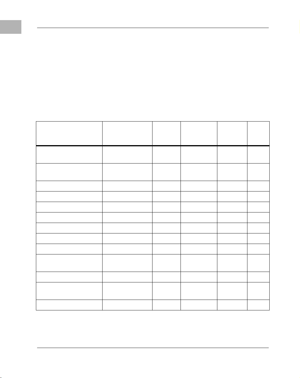
Table 1-3. 200/300-Series MVME172 Local Bus Memory Map
MVME172.
Address Range Devices Accessed
Programmable DRAM on parity
mezzanine
Programmable DRAM on ECC
mezzanine
Programmable Onboard SRAM D32 1 28KB N 2
Programmable VMEbus A32/A24 D32-D16 -- ? 4
Programmable IP_a memory D32-D8 64KB-8MB ? 2, 4
Programmable IP_b memory D32-D8 64KB-8MB ? 2, 4
$FF800000-$FF9FFFFF Flash/EPROM D32 2MB N 1, 5
$FFA00000-$FFBFFFFF EPROM/Flash D32 2MB N 5
$FFC00000-$FFDFF F FF Not decoded D32 2MB N
$FFE00000-$FFE1FFFF Onboard
SRAM default
$FFE80000-$FFEFFFFF Not decoded -- 512KB N 6
$FFF00000-$FFFEFFFF Local I/O devices
(see next table)
Port
Width
D32 4MB-16MB N 2
D32 4MB-64MB N 2
D32 128KB N
D32-D8 878KB Y 3
Size
Software
Cache
Inhibit
Notes
$FFFF0000-$FFFFFFFF VMEbus A16 D32/D16 64KB ? 2, 4
1-10 Computer Group Literature Center Web Site
Page 29

Memory Maps
Notes 1. Devices mapped at $FFF80000-$FFF9FF FF also appear at
$00000000- $001FFFFF when the ROM0 bit in the MC2
chip EPROM control register is high (ROM0=1). ROM0 is
set to 1 after each r eset. The ROM0 bit must be clea red before
other resources (DRAM or SRAM) can be mapped in this
range ($00000000 - $001FFFFF).
The EPROM/Flash memory map is also controlled by the
EPROM size and by control bit V11 in the MC2 chip ASIC.
Refer to th e EPROM/Flash configuration tables in your
MVME172 installation manual for further details.
2. This area is user-programmable. The DRAM and SRAM
decoder is programmed in the MC2 chip, the local-toVMEbus decoders are programmed in the VMEchip2, and
the IP memory space is programmed in the IP2.
3. Size is approximate.
4. Cache inhibit depends on the devices in the area mapped.
5. The EPROM and Flash are dynamicall y sized by the MC2
chip ASIC from an 8-bi t privat e b us to the 32- bit MPU lo cal
bus.
1
6. These areas are not decoded unless one of the
programmable decoder s is in itiali zed to de code t his spac e. If
they are not decoded an d the local timer is enabled, an ac cess
to this address range will generate a local bus time-out.
http://www.mcg.mot.com/literature 1-11
Page 30
1
Board Description and Memory Maps
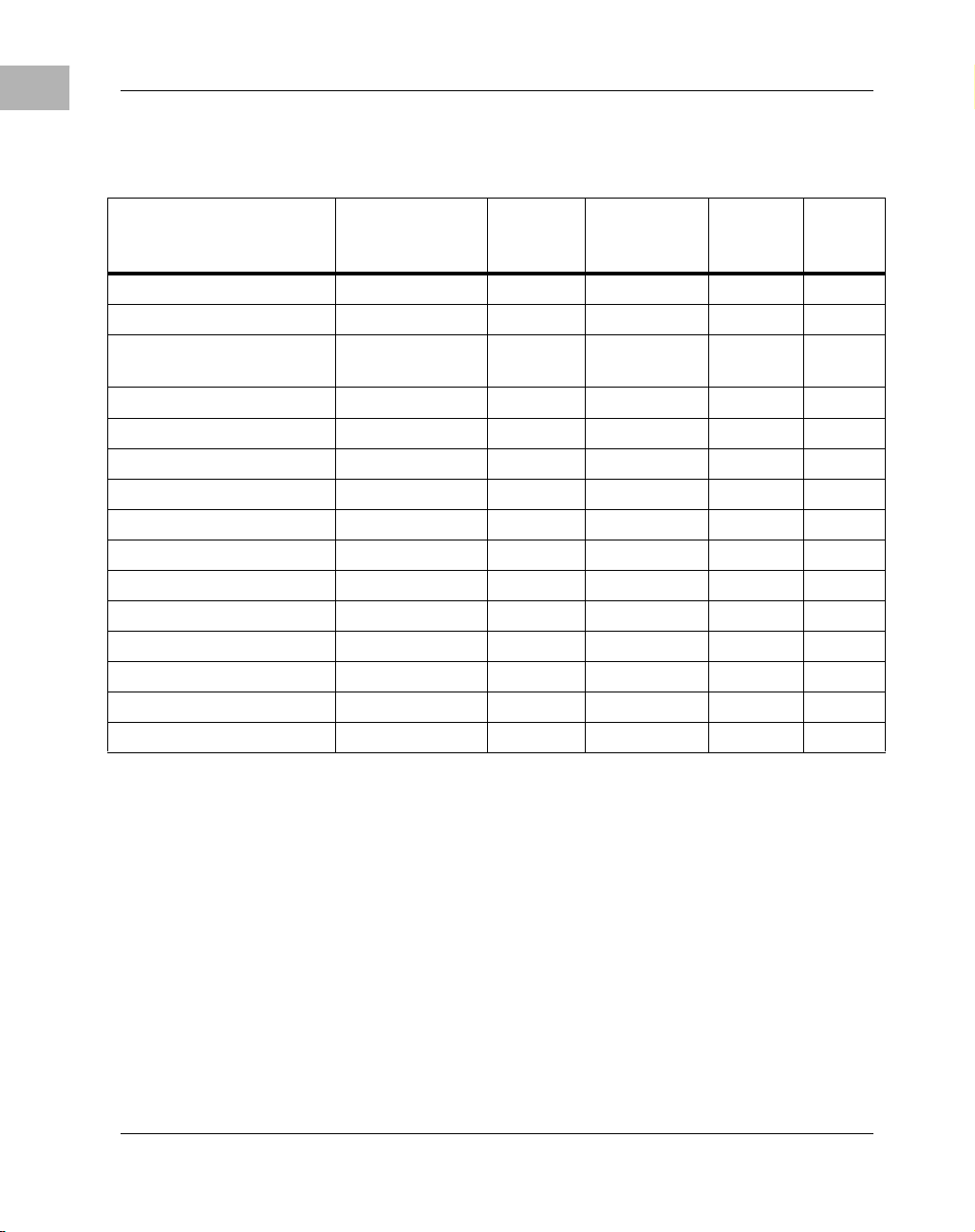
Table 1-4. 400/500-Series MVME172 Local Bus Memory Map
Address Range
Programmable DRAM on board D32 4MB-16 MB N 2
Programmable SRAM D32 128KB-2MB N 2
Programmable VMEbus
Programmable IP_a Memory D32-D8 64KB-8MB ? 2, 4
Programmable IP_b Memory D32-D8 64KB-8MB ? 2, 4
Programmable IP_c Memory D32-D8 64KB-8MB ? 2, 4
Programmable IP_d Memory D32-D8 64KB-8MB ? 2, 4
$FF800000 - $FF9FFFFF Flash/PROM D32 2MB N 1, 5
$FFA00000 - $FFBFFFFF PROM/Flash D32 2MB N 6
$FFC00000 - $FFCFFFFF Not decoded -- 1MB N 7
$FFD00000 - $FFDFFFFF Not decoded -- 1MB N 7
$FFE00000 - $FFE7FFFF SRAM default D32 512KB N -$FFE80000 - $FFEFFFFF Not decoded - - 512KB N 7
$FFF00000 - $FFFEFFFF Local I/O D32-D8 878KB Y 3
$FFFF0000 - $FFFFFFFF VMEbus A16 D32/D16 64KB ? 2, 4
Devices
Accessed
A32/A24
Port
Width
D32/D16 -- ? 4
Size
Software
Cache
Inhibit
Note(s)
Notes 1. Reset enables the decoder for this space of the memory
map so that it will decode address spaces
$FF800000-$FF9FFFFF and $00000000-$003FFFFF. The
decode at 0 must be disabled in the MC2 chip befor e DRAM
is enabled. DRAM is enabled with the DRAM Control
1-12 Computer Group Literature Center Web Site
Page 31

Memory Maps
Register at address $FFF42048, bit 24. PROM/Flash is
disabled at the low address space with PROM Control
Register at address $FFF42040, bit 20.
2. This area is user-programmable. The DRAM and SRAM
decoder is programmed in the MC2 chip, the
local-to-VMEbus decoders are programmed in the
VMEchip2, and the IP memory space is programmed in the
IP2 chip.
3. Size is approximate.
4. Cache inhibit depends on devices in area mapped.
5. The PROM and Flash are sized by the MC2 chip ASIC
from an 8-bit private bus to the 32-bit MPU local bus.
Because the device size is less than the allocated memory
map size for some entries, the device c ontents repeat for
those entries.
If jumper GPI3 is installed, the Flash device is accessed. If
GPI3 is not installed, the PROM is accessed.
1
6. The Flash and PROM are sized by the MC2 chip ASIC
from an 8-bit private bus to the 32-bit MPU local bus.
Because the device size is less than the allocated memory
map size for some entries, the device c ontents repeat for
those entries.
If jumper GPI3 is inst alled, the PROM is accessed. If GPI3 i s
not installed, the Flash device is accessed.
7. These areas are not decoded unless one of the
programmable decoders are initialized to decode this space.
If they are not decoded, an access to this address range will
generate a local bus time-o ut. The local bus timer must be
enabled.
http://www.mcg.mot.com/literature 1-13
Page 32

1
Board Description and Memory Maps
Table 1-5 below and Table 1-6 on page 1-18 describe the "Local I/O
Devices" portion of t he local bus main memory map fo r the 200/300-Series
and 400/500-Series MVME172, respectively.
Table 1-5. 200/300-Series MVME172 Local I/O Devices Memory Map
Address Range Devices Accessed Port
Width
$FFF00000 - $FFF3FFFF Reserved - - 256K
$FFF40000 - $FFF400FF V MEchip2 (LCSR) D32 256B 1, 3
$FFF40100 - $FFF401FF VMEchip2 (GCSR) D32-D8 256B 1, 3
$FFF40200 - $FFF40FFF Reserved - - 3.5KB 4, 5
$FFF41000 - $FFF41FFF Reserved - - 4KB 4
$FFF42000 - $FFF42FFF MC2 chip D32-D8 4KB 1
$FFF43000 - $FFF430FF MCECC #1 D8 256B 1, 8
$FFF43100 - $FFF431FF MCECC #2 D8 256B 1, 8
$FFF43200 - $FFF43FFF MCECCs (repeated) - - 3.5KB 1, 5, 8
$FFF44000 - $FFF44FFF Reserved - - 8KB 4
$FFF45000 - $FFF45800 SCC #1 (Z85230) D8 2KB 1, 2
$FFF45801 - $FFF45FFF SCC #2 (Z85230) D8 2KB 1, 2
$FFF46000 - $FFF46FFF LAN (82596CA) D32 4KB 1, 6
$FFF47000 - $FFF47FFF SCSI (53C710) D32-D8 4KB 1
Size Notes
4
B
$FFF48000 - $FFF57FFF Reserved - - 64KB 4
$FFF58000 - $FFF5807F IP2 IP_a I/O D16 128B 1
$FFF58080 - $FFF580FF IP2 IP_a ID D16 128B 1
$FFF58100 - $FFF5817F IP2 IP_b I/O D16 128B 1
$FFF58180 - $FFF581FF IP2 IP_b ID Read D16 128B 1
$FFF58200 - $FFF5827F IP2 IP_c I/O D16 128B 7
1-14 Computer Group Literature Center Web Site
Page 33

Memory Maps
Table 1-5. 200/300-Series MVME172 Local I/O Devices Memory Map
(Continued)
1
Address Range Devices Accessed Port
Width
$FFF58280 - $FFF582FF IP2 IP_c ID D16 128B 7
$FFF58300 - $FFF5837F IP2 IP_d I/O D16 128B 7
$FFF58380 - $FFF583FF IP2 IP_d ID Read D16 128B 7
$FFF58400 - $FFF584FF IP2 IP_ab I/O D32-D16 256B 1
$FFF58500 - $FFF585FF IP2 IP_cd I/O D32-D16 256B 7
$FFF58600 - $FFF586FF IP2 IP_ab I/O Repeated D32-D16 256B 1
$FFF58700 - $FFF587FF IP2 IP_cd I/O Repeated D32-D16 256B 7
$FFF58800 - $FFF5887F Reserve d - - 128B 1
$FFF58880 - $FFF588FF Reserved - - 128B 1
$FFF58900 - $FFF5897F Reserve d - - 128B 1
$FFF58980 - $FFF589FF Reserved - - 128B 1
$FFF58A00 - $FFF58A7F Reserved - - 128B 1
$FFF58A80 - $FFF58AFF Reserved - - 128B 1
$FFF58B00 - $FFF58B7F Reserved - - 128B 1
$FFF58B80 - $FFF58BFF Reserved - - 128B 1
Size Notes
$FFF58C00 - $FFF58CFF Reserved - - 256B 1
$FFF58D00 - $FFF58DFF Reserved - - 256B 1
$FFF58E00 - $ FFF58EFF Reserved - - 256B 1
$FFF58F00 - $FFF58FFF Reserved - - 256B 1
$FFFBC000 - $FFFBC01F IP2 Registers D32-D8 2KB 1
http://www.mcg.mot.com/literature 1-15
Page 34

1
Board Description and Memory Maps
Table 1-5. 200/300-Series MVME172 Local I/O Devices Memory Map
(Continued)
Address Range Devices Accessed Port
Width
$FFFBC800 - $FFFBC81F Reserved - - 2KB 1
$FFFBD000 - $FFFBFFFF Reserved - - 12KB 4
$FFFC0000 - $FFFCFFFF M48T58 (BBRAM, TOD Clock) D32-D8 64KB 1, 9
$FFFD0000 - $FFFEFFFF Reserved - - 128K
Size Notes
4
B
1-16 Computer Group Literature Center Web Site
Page 35

Memory Maps
Notes 1. For a complete description of the regist er bits , refe r to the
data sheet for th e specific chip. For a m ore detailed memory
map, refer to the following detailed peripheral device
memory maps.
2. The SCC is an 8-bit device located on an MC2 chip pr ivate
data bus. Byte access is required.
3. Writes to the LCSR in the VMEchip2 must be 32 bits.
LCSR writes of 8 or 16 bits terminate with a TEA signal.
Writes to the GCSR may be 8, 16 or 32 bits. Reads to the
LCSR and GCSR may be 8, 16 or 32 bits. Byte reads should
be used to r ead the interrupt vector.
4. This area does not return an acknowledge signal. If the
local bus timer is enabled, the access times out and is
terminated by a TEA signal.
5. Size is approximate.
6. Port commands to the 82596CA must be writt en as two 16bit writes: upper word first and lower word second.
1
7. Not used.
8. To use this area, the ECC mezzanine board must be
installed. If it is not installed, no acknowledge signal is
returned; if the local bus timer is enabled, the access times
out and is terminated by a TEA signal.
9.Repeats on 8KB boundaries.
http://www.mcg.mot.com/literature 1-17
Page 36

1
Board Description and Memory Maps
Table 1-6. 400/500-Series MVME172 Local I/O Devices Memory Map
Address Range Device
Port
Width
Size Note(s)
$FFF00000 - $FFF3FFFF Reserved -- 256KB 4
$FFF40000 - $FFF400FF V MEchip2 (LCSR) D32 256B 1, 3
$FFF40100 - $FFF401FF V MEchip2 (GCSR) registers D32-D8 256B 1, 3
$FFF40200 - $FFF40FFF Reserved -- 3.5KB 4, 5
$FFF41000 - $FFF41FFF Reserved -- 4KB 4
$FFF42000 - $FFF42FFF MC2 chip D32-D8 4KB 1
$FFF43000 - $FFF44FFF Reserved -- 8KB 4
$FFF45000 - $FFF45FFF SCC (Z85230) D8 4KB 1, 2
$FFF46000 - $FFF46FFF LAN (82596CA) D32 4KB 1, 6
$FFF47000 - $FFF47FFF SCSI (53C710) D32-D8 4KB 1
$FFF48000 - $FFF57FFF Reserved -- 64KB 4
$FFF58000 - $FFF5807F IP2 chip IP_a I/O D16 128B 1
$FFF58080 - $FFF580FF IP2 chip IP_a ID D16 128B 1
$FFF58100 - $FFF5817F IP2 chip IP_b I/O D16 128B 1
$FFF58180 - $FFF581FF IP2 chip IP_b ID Read D16 128B 1
$FFF58200 - $FFF5827F IP2 chip IP_c I/O D16 128B 1
$FFF58280 - $FFF582FF IP2 chip IP_c ID D16 128B 1
$FFF58300 - $FFF5837F IP2 chip IP_d I/O D16 128B 1
$FFF58380 - $FFF583FF IP2 chip IP_d ID Read D16 128B 1
$FFF58400 - $FFF584FF IP2 chip IP_ab I/O D32-D16 256B 1
$FFF58500 - $FFF585FF IP2 chip IP_cd I/O D32-D16 256B 1
$FFF58600 - $FFF586FF IP2 chip IP_ab I/O repeated D32-D16 256B 1
$FFF58700 - $FFF587FF IP2 chip IP_cd I/O repeated D32-D16 256B 1
$FFF58800 - $FFF5887F Reserved -- 128B 1
$FFF58880 - $FFF588FF Reserved -- 128B 1
$FFF58900 - $FFF5897F Reserved -- 128B 1
1-18 Computer Group Literature Center Web Site
Page 37

Memory Maps
Table 1-6. 400/500-Series MVME172 Local I/O Devices Memory Map
(Continued)
1
Address Range Device
$FFF58980 - $FFF589FF Reserved -- 128B 1
$FFF58A00 - $FFF58A7F Reserved -- 128B 1
$FFF58A80 - $FFF58AFF Reserved -- 128B 1
$FFF58B00 - $FFF58B7F Reserved -- 128B 1
$FFF58B80 - $FFF58BFF Reserved -- 128B 1
$FFF58C00 - $FFF58CFF Reserved -- 256B 1
$FFF58D00 - $FFF58DFF Reserved -- 256B 1
$FFF58E00 - $FFF58EFF Reserved -- 256B 1
$FFF58F00 - $FFF58FFF Reserved -- 256B 1
$FFFBC000 - $FFFBC01F IP2 chip registers D32-D8 2KB 1
$FFFBC800 - $FFFBC81F Reserved -- 2KB 1
$FFFBD000 -
$FFFBFFFF
$FFFC0000 - $FFFC7FFF MK48T58
$FFFC8000 - $FFFCBFFF MK48T58 D32-D8 16KB 1, 7
$FFFCC000 - $FFFCFFFF MK48T58 D32-D8 16KB 1, 7
$FFFD0000 - $FFFEFFFF Reserved -- 128KB 4
Reserved -- 12KB 4
(BBRAM, TOD clock)
Port
Width
D32-D8 32KB 1
Size Note(s)
http://www.mcg.mot.com/literature 1-19
Page 38

1
Board Description and Memory Maps
Notes 1. For a complete description of the regist er bits , refe r to the
data sheet for th e specific chip. For a m ore detailed memory
map, refer to the following detailed peripheral device
memory maps.
2. The SCC is an 8-bit device located on an MC2 chip pr ivate
data bus. Byte access is required.
The data register of the Zilog Z85230 device which is
interfaced by the MC2 chip ASIC cannot be accessed. The
Zilog Z85230 has an indirect access mode to the data
registers which is functional and must be used.
3. Writes to the LCSR in the VMEchip2 must be 32 bits.
LCSR writes of 8 or 16 bits terminate with a TEA signal.
Writes to the GCSR may be 8, 16 or 32 bits. Reads to the
LCSR and GCSR may be 8, 16 or 32 bits. Byte reads should
be used to r ead the interrupt vector.
4. This area does not return an acknowledge signal. If the
local bus timer is enabled, the access times out and is
terminated by a TEA signal.
5. Size is approximate.
6. Port commands to the 82596CA must be written as two
16-bit writes: upper word first and lower word second.
7. Refer to the Fl ash and PROM Interf ace section in t he MC2
chip description in Chapter 3.
1-20 Computer Group Literature Center Web Site
Page 39

Detailed I/O Memory Maps
Tables 1-7 through 1-17 give the detailed memory maps for:
VMEchip2 Table 1-7
MC2 chip Table 1-8
IP2 chip Table 1-9
IP2 chip Control and Status Register s Table 1-10
MCECC chip Table 1-11
Z85230 SCC Register addresses Table 1-12
82596CA Ethernet LAN chip Table 1-13
53C710 SCSI chip Table 1-14
MK48T58 BBRAM/TOD clock Table 1-15
BBRAM configuration area Table 1-16
TOD clock Table 1-17
Memory Maps
1
Note Manufacturers’ errata sheets for the various chips are
available by contacting your local Motorola sales
representative. A no n-disclo sure agr eement may be require d.
http://www.mcg.mot.com/literature 1-21
Page 40

1
Board Description and Memory Maps
Table 1-7. VMEchip2 Memory Map (Sheet 1 of 3)
VMEchip2 LCSR Base Address = $FFF40000
OFFSET:
16171819202122232425262728293031
0
SLAVE ENDING ADDRESS 1
10
14
18
1C
20
24
28
2C
30
34
38
4
8
C
ADDER
2
SLAVE ENDING ADDRESS 2
SLAVE ADDRESS TRANSLATION ADDRESS 1
SLAVE ADDRESS TRANSLATION ADDRESS 2
SNP
WP2SUP2USR2A322A24
2
BLK
BLK2PRGM2DATA
D64
2
2
2
16171819202122232425262728293031
MASTER ENDING ADDRESS 1
MASTER ENDING ADDRESS 2
MASTER ENDING ADDRESS 3
MASTER ENDING ADDRESS 4
MASTER ADDRESS TRANSLATION ADDRESS 4
MAST
D16
MAST
WP
EN
EN
GCSR GROUP SELECT
MAST
MAST
D16
WP
EN
EN
BOARD SELECT
GCSR
MASTER AM 3MASTER AM 4
MAST
MAST
MAST
4
3
EN
EN
MAST
2
1
EN
EN
16171819202122232425262728293031
WAIT
RMW
ROM
ZERO
DMA TB
SNP MODE
SRAM
SPEED
DMA CONTROLLER
3C
40
44
48
TICK
2/1
TICK
IRQ 1
EN
CLR
IRQ
IRQ
STAT
VMEBUS
INTERRUPT
LEVEL
VMEBUS INTERRUPT VECTOR
DMA CONTROLLER
DMA CONTROLLER
DMA CONTROLLER
This sheet continues on facing page.
1-22 Computer Group Literature Center Web Site
Page 41

ADDER
MAST
MAST
WP
D16
EN
IO2ENIO2
ARB
ROBN
DMA
TBL
INT
EN
WP
EN
MAST
DHB
DMA LB
SNP MODE
IO2
S/U
MAST
DWB
MASTER AM 2 MASTER AM 1
IO2
IO1ENIO1
P/D
MST
FAIR
DMA
INC
VME
LOCAL BUS ADDRESS COUNTER
SLAVE STARTING ADDRESS 1
SLAVE STARTING ADDRESS 2
SLAVE ADDRESS TRANSLATION SELECT 1
SLAVE ADDRESS TRANSLATION SELECT 2
SNP
1
1
WP1SUP1USR1A321A24
MASTER STARTING ADDRESS 1
MASTER STARTING ADDRESS 2
MASTER STARTING ADDRESS 3
MASTER STARTING ADDRESS 4
MASTER ADDRESS TRANSLATION SELECT 4
MAST
MAST
WP
D16
EN
D16
EN
MST
RWD
DMA
INC
LB
IO1
WP
EN
MASTER
VMEBUS
DMA
WRT
IO1
S/U
DMA
D16
EN
DMA
HALT
DMA
D64
BLK
ROM
SIZE
DMAENDMA
DMA
BLK
ROM BANK B
TBL
DMA
AM
5
1
SPEED
DMA
FAIR
DMA
AM
4
BLK
BLK1PRGM1DATA
D64
1
DM
RELM
DMA
DMA
AM
3
Memory Maps
ROM BANK A
SPEED
DMA
VMEBUS
DMA
AM
AM
2
1
DMA
AM
1
0123456789101112131415
1
0123456789101112131415
0123456789101112131415
0
VMEBUS ADDRESS COUNTER
BYTE COUNTER
TABLE ADDRESS COUNTER
MPU
MPU
MPU
MPU
MPU
DMA
DMA
DMA
DMA
DMA
DMA
DMA TABLE
INTERRUPT COUNT
CLR
STAT
LBE
ERR
LPE
ERR
LOB
ERR
LTO
ERR
LBE
ERR
LPE
ERR
LOB
ERR
LTO
ERR
TBL
ERR
VME
ERR
DMA
DONE
1360 9403
This sheet begins on facing page.
http://www.mcg.mot.com/literature 1-23
Page 42

1
Board Description and Memory Maps
Table 1-7. VMEchip2 Memory Map (Sheet 2 of 3)
VMEchip2 LCSR Base Address = $FFF40000
OFFSET:
4C
50
ARB
BGTO
EN
DMA
TIME OFF
DMA
TIME ON
TICK TIMER 1
VME
GLOBAL
TIMER
16171819202122232425262728293031
54
58
5C
60
64
68
6C
70
74
78
7C
80
84
88
8C
SCON BRD
AC
AB
FAIL
IRQ
IRQ
EN
EN
IRQ
IRQ
31
30
CLR
CLR
IRQ
IRQ
31
30
VECTOR BASE
REGISTER 0
SYS
FAIL
SYS
FAIL
IRQ
EN
IRQ
29
CLR
IRQ
29
AC FAIL
IRQ LEVEL
VME IACK
IRQ LEVEL
SW7
IRQ LEVEL
SPARE
IRQ LEVEL
FAIL
STAT
MWP
BERR
IRQ
EN
IRQ
28
CLR
IRQ
28
PURS
STAT
PE
IRQ
EN
IRQ
27
CLR
IRQ
27
CLR
BRD
PURS
FAIL
STAT
OUT
IRQ1E
TIC2
IRQ
IRQ
EN
EN
IRQ
IRQ
26
25
CLR
CLR
IRQ
IRQ
26
25
ABORT
IRQ LEVEL
DMA
IRQ LEVEL
SW6
IRQ LEVEL
VME IRQ 7
IRQ LEVEL
VECTOR BASE
REGISTER 1
RST
SW
EN
TIC1
IRQ
EN
IRQ
CLR
IRQ
24
24
SYS
RSTWDCLR
VME
DMA
IACK
IRQ
EN
IRQ
23
CLR
IRQ
23
MST
SYS
IRQ
FAIL
EN
LEVEL
TO
IRQ
EN
IRQ
22
CLR
IRQ
22
WD
CLR
CNT
SIG3
IRQ
EN
IRQ
21
CLR
IRQ
21
SYS FAIL
IRQ LEVEL
SIG 3
IRQ LEVEL
SW5
IRQ LEVEL
VME IRQ 6
IRQ LEVEL
AC
FAIL
LEVEL
WD
TO
STAT
SIG2
IRQ
EN
IRQ
20
CLR
IRQ
20
ABORT
LEVEL
TO
BF
EN
SIG1
IRQ
EN
IRQ
19
CLR
IRQ
19
TICK TIMER 1
TICK TIMER 2
TICK TIMER 2
WD
SRST
RST
LRST
SIG0
IRQ
EN
IRQ
18
CLR
IRQ
18
MST WP ERROR
IRQ LEVEL
SIG 2
IRQ LEVEL
SW4
IRQ LEVEL
VME IRQ 5
IRQ LEVEL
GPIOEN
WD
ENWDEN
LM1
IRQ
EN
IRQ
17
CLR
IRQ
17
PRE
16171819202122232425262728293031
LM0
IRQ
EN
IRQ
16
CLR
IRQ
16
This sheet continues on facing page.
1-24 Computer Group Literature Center Web Site
Page 43

Memory Maps
1
VME
ACCESS
TIMER
LOCAL
BUS
TIMER
COMPARE REGISTER
COUNTER
COMPARE REGISTER
COUNTER
OVERFLOW
COUNTER 2
SCALER
SW7
SW6
IRQ
EN
IRQ
14
SET
IRQ
14
CLR
IRQ
14
P ERROR
IRQ LEVEL
IRQ LEVEL
IRQ LEVEL
VME IRQ 4
IRQ LEVEL
GPIOO
SW5
IRQ
EN
IRQ
13
SET
IRQ
13
CLR
IRQ
13
SIG 1
SW3
IRQ
EN
IRQ
SET
IRQ
CLR
IRQ
15
15
15
SW4
IRQ
IRQ
SET
IRQ
CLR
IRQ
0123456789101112131415
TIME OUT
SELECT
CLR
OVF
2
WD
COC
EN
TIC
EN
2
2
OVERFLOW
COUNTER 1
PRESCALER
CLOCK ADJUST
CLR
OVF
TIC
COC
EN
EN
1
1
1
0123456789101112131415
SW3
SW2
SW1
SW0
IRQ
IRQ
IRQ
EN
EN
EN
IRQ
12
11
SET
IRQ
12
11
CLR
IRQ
12
11
EN
IRQ
IRQ
10
9
SET
SET
IRQ
IRQ
10
9
CLR
CLR
IRQ
IRQ
10
9
IRQ1E
IRQ LEVEL
SIG 0
IRQ LEVEL
SW2
IRQ LEVEL
VMEB IRQ 3
IRQ LEVEL
GPIOI GPI
IRQ
EN
IRQ
SET
IRQ
CLR
IRQ
8
8
8
SPARE VME
EN
IRQ
7
MP
IRQ
EN
IRQ7
EN
IRQ
6
REV
EROM
VME
IRQ6
EN
IRQ
5
TIC TIMER 2
IRQ LEVEL
LM 1
IRQ LEVEL
SW1
IRQ LEVEL
VME IRQ 2
IRQ LEVEL
DIS
SRAM
VME
IRQ5
IRQ
DIS
MST
VME
VME
VME
IRQ4
IRQ3
EN
EN
EN
IRQ
3
NO
EL
BBSY
IRQ
2
TIC TIMER 1
DIS
BSYTENINT
4
IRQ2
EN
IRQ
1
IRQ LEVEL
LM 0
IRQ LEVEL
SW0
IRQ LEVEL
VME IRQ 1
IRQ LEVEL
VME
IRQ1
EN
IRQ
DIS
BGN
0
1361 9403
This sheet begins on facing page.
http://www.mcg.mot.com/literature 1-25
Page 44

1
Board Description and Memory Maps
Table 1-7. VMEchip2 Memory Map (Sheet 3 of 3)
VMEchip2 GCSR Base Address = $FFF40100
Offsets Bit Numbers
VME
-bus
Local
Bus
1514131211109876543210
0 0 Chip Revision Chip ID
24
LM3LM2LM1LM0SIG3SIG2SIG1SIG0RSTISF BF SCONSYS
4 8 General Purpose Control and Status Register 0
6 C General Purpose Control and Status Register 1
8 10 General Purpose Control and Status Register 2
A 14 General Purpose Control and Status Register 3
C 18 General Purpose Control and Status Register 4
E 1C General Purpose Control and Status Register 5
XXX
FL
1-26 Computer Group Literature Center Web Site
Page 45

1Board Description and Memory Maps
0Memory Maps
Memory Maps
Table 1-8. MC2 Chip Register Map
MC2 Chip Base Address = $FFF42000
Offset D31-D24 D23-D16 D15-D8 D7-D0
$00 MC2 chip ID MC2 chip
Revision
$04 Tick Timer 1 Compare Register
$08 Tick Timer 1 Counter Register
$0C Tick Timer 2 Compare Register
$10 Tick Timer 2 Counter Register
$14 LSB Prescaler
Count Register
$18 Tick Timer 4
Interrupt Control
$1C DRAM Parity Error
Interrupt Control
$20 DRAM Space Base Address Register SRAM Space Base Address Register
$24 DRAM Space
Size
$28 LANC Error Status Reserved LANC Interrupt
$2C SCSI Error Status General Purpose
$30 Tick Timer 3 Compare Register
$34 Tick Timer 3 Counter Register
$38 Tick Timer 4 Compare Register
$3C Tick Timer 4 Counter Register
$40 Bus Clock EPROM Access
$44
$48 DRAM Control Reserved MPU Status Reserved
$4C 32-bit Prescaler Count Register
RESET Switch
Control
Prescaler
Clock Adjust
Tic k Timer 3
Interrupt Control
SCC Interrupt
Control
DRAM/SRAM
Options
Inputs
Time Control
Watchdog Timer
Control
General
Control
Tic k Timer 2
Control
Tic k Timer 2
Interrupt Control
Tic k Timer 4
Control
SRAM Space
Size
Control
MVME172 Version SCSI Interrupt
Flash Parameter
Control
Access &
Watchdog Time
Base Select
Interrupt Vector
Base Register
Tic k Timer 1
Control
Tic k Timer 1
Interrupt Control
Tic k Timer 3
Control
Reserved
LANC Bus Error
Interrupt Control
Control
ABORT Switch
Interrupt Control
Reserved
1
http://www.mcg.mot.com/literature 1-27
Page 46

1
Board Description and Memory Maps
The following memory ma p ta bl e includes all devices sel ected by the IP2
chip map decoder.
Table 1-9. IP2 Chip Overall Memory Map
Address Range Selected Device Port Width Size
Programmable IP_a/IP_ab Memory Space D32-D8 64KB-16MB
Programmable IP_b Memory Space D16-D8 64KB-8MB
Programmable IP_c/IP_cd Memory Space D32-D8 64KB-16MB
Programmable IP_d Memory Space D16-D8 64KB-8MB
$FFF58000-$FFF5807F IP_a I/O Space D16 128B
$FFF58080-$FFF580BF IP_a ID Space D16 64B
$FFF580C0-$FFF580FF IP_a ID Space Repeated D16 64B
$FFF58100-$FFF5817F IP_b I/O Space D16 128B
$FFF58180-$FFF581BF IP_b ID Space D16 64B
$FFF581C0-$FFF581FF IP_b ID Space Repeated D16 64B
$FFF58200-$FFF5827F IP_c I/O Space D16 128B
$FFF58280-$FFF582BF IP_c ID Space D16 64B
$FFF582C0-$FFF582FF IP_c ID Space Repeated D16 64B
$FFF58300-$FFF5837F IP_d I/O Space D16 128B
$FFF58380-$FFF583BF IP_d ID Space D16 64B
$FFF583C0-$FFF583FF IP_d ID Space Repeated D16 64B
$FFF58400-$FFF584FF IP_ab I/O Space D32-D16 256B
$FFF58500-$FFF585FF IP_cd I/O Space D32-D16 256B
$FFF58600-$FFF586FF IP_ab I/O Space Repeated D32-D16 256B
$FFF58700-$FFF587FF IP_cd I/O Space Repeated D32-D16 256B
$FFFBC000-$FFFBC083 Control/ Status Registers D32-D8 32B
A summary of the IP2 c hip CSR registers is s hown in Table 1-10 . The CSR
registers can be accessed as bytes, words, or longwords. They should not
be accessed as lines. They are shown in the table as bytes.
1-28 Computer Group Literature Center Web Site
Page 47

Memory Maps
Table 1-10. IP2 Chip Memory Map - Control and Status Registers
IP2 Chip Base Address = $FFFBC000
Register
Offset
$00CHIP ID00100011
$01 CHIP
$02RESERVED00000000
$03 VECTOR B A S E IV7 IV6 IV5 IV4 IV3 IV2 IV1 IV0
$04 IP_a MEM
$05 IP_a MEM
$06 IP_b MEM
$07 IP_b MEM
$08 IP_c MEM
$09 IP_c MEM
$0A IP_d MEM
$0B IP_d MEM
$0C IP_a MEM
$0D IP_b MEM
$0E IP_c MEM
$0F IP_d MEM
$10 IP_a INT0
$11 IP_a INT1
$12 IP_b INT0
$13 IP_b INT1
$14 IP_c INT0
$15 IP_c INT1
$16 IP_d INT0
$17 IP_d INT1
Register
Name
REVISION
BASE UPPER
BASE LOWER
BASE UPPER
BASE LOWER
BASE UPPER
BASE LOWER
BASE UPPER
BASE LOWER
SIZE
SIZE
SIZE
SIZE
CONTROL
CONTROL
CONTROL
CONTROL
CONTROL
CONTROL
CONTROL
CONTROL
D7 D6 D5 D4 D3 D2 D1 D0
00000001
a_BASE31 a_BASE30 a_BASE29 a_BASE28 a_BASE27 a_BASE26 a_BASE25 a_BASE24
a_BASE23 a_BASE22 a_BASE21 a_BASE20 a_BASE19 a_BASE18 a_BASE17 a_BASE16
b_BASE31 b_BASE30 b_BASE29 b_BASE28 b_BASE27 b_BASE26 b_BASE25 b_BASE24
b_BASE23 b_BASE22 b_BASE21 b_BASE20 b_BASE19 b_BASE18 b_BASE17 b_BASE16
c_BASE31 c_BASE30 c_BASE29 c_BASE28 c_BASE27 c_BASE26 c_BASE25 c_BASE24
c_BASE23 c_BASE22 c_BASE21 c_BASE20 c_BASE19 c_BASE18 c_BASE17 c_BASE16
d_BASE31 d_BASE30 d_BASE29 d_BASE28 d_BASE27 d_BASE26 d_BASE25 d_BASE24
d_BASE23 d_BASE22 d_BASE21 d_BASE20 d_BASE19 d_BASE18 d_BASE17 d_BASE16
a_SIZE23 a_SIZE22 a_SIZE21 a_SIZE20 a_SIZE19 a_SIZE18 a_SIZE17 a_SIZE16
b_SIZE23 b_SIZE22 b_SIZE21 b_SIZE20 b_SIZE19 b_SIZE18 b_SIZE17 b_SIZE16
c_cSIZE23 c_SIZE22 c_SIZE21 c_SIZE20 c_SIZE19 c_SIZE18 c_SIZE17 c_SIZE16
d_SIZE23 d_SIZE22 d_SIZE21 d_SIZE20 d_SIZE19 d_SIZE18 d_SIZE17 d_SIZE16
a0_PLTY a0_E/L* a0_INT a0_IEN a0_ICLR a0_IL2 a0_IL1 a0_IL0
a1_PLTY a1_E/L* a1_INT a1_IEN a1_ICLR a1_IL2 a1_IL1 a1_IL0
b0_PLTY b0_E/L* b0_INT b0_IEN b0_ICLR b0_IL2 b0_IL1 b0_IL0
b1_PLTY b1_E/L* b1_INT b1_IEN b1_ICLR b1_IL2 b1_IL1 b1_IL0
c0_PLTY c0__E/L* c0__INT c0__IEN c0__ICLR c0__IL2 c0__IL1 c0__IL0
c1_PLTY c1__E/L* c1__INT c1__IEN c1__ICLR c1__IL2 c1__IL1 c1__IL0
d0_PLTY d0__E/L* d 0__INT d0__IEN d0__ICLR d0__IL2 d0__IL1 d0__I L0
d1_PLTY d1__E/L* d 1__INT d1__IEN d1__ICLR d1__IL2 d1__IL1 d1__I L0
Register Bit Names
1
http://www.mcg.mot.com/literature 1-29
Page 48

1
Board Description and Memory Maps
Table 1-10. IP2 Chip Memory Map - Control and Status Registers
(Continued)
Register
Offset
$18 IP_a
$19 IP_b
$1A IP_c
$1B IP_d
$1CRESERVED00000000
$1DIP CLOCK0000000IP32
$1E DMA
$1FIP RESET0000000RES
Register
Name
GENERAL
CONTROL
GENERAL
CONTROL
GENERAL
CONTROL
GENERAL
CONTROL
ARBITRATION
CONTROL
D7 D6 D5 D4 D3 D2 D1 D0
a_ERR 0 a_RT1 a_RT0 a_WIDTH1 a_WIDTH0 a_BTD a_MEN
b_ERR 0 b_RT1 b_RT0 b_WIDTH1 b_WIDTH0 b_BTD b_MEN
c_ERR 0 c_RT1 c_RT0 c_WIDTH1 c_WIDTH0 c_BTD c_MEN
d_ERR 0 d_RT1 d_RT0 d_WIDTH1 d_WIDTH0 d_BTD d_MEN
00000ROTATPRI1PRI0
Register Bit Names
1-30 Computer Group Literature Center Web Site
Page 49

Memory Maps
Table 1-10. IP2 Chip Memory Map - Control and Status Registers
(Continued)
Register
Offset
$20 DMA_a
$21 DMA_a INT
$22DMA ENABLE0000000DEN
$23RESERVED00000000
$24 DMA_a CON-
$25 DMA_a
$26RESERVED00000000
$27RESERVED00000000
$28 DMA_a LB
$29 DMA_a LB
$2A DMA_a LB
$2B DMA_a LB
$2C DMA_a IP
$2D DMA_a IP
$2E DMA_a IP
$2F DMA_a IP
$30 DMA_a BYTE
$31 DMA_a BYTE
$32 DMA_a BYTE
$33 DMA_a BYTE
$34 DMA_a TBL
$35 DMA_a TBL
$36 DMA_a TBL
$37 DMA_a TBL
Register
Name
STATUS
CTRL
TROL 1
CONTROL 2
ADDR
ADDR
ADDR
ADDR
ADDR
ADDR
ADDR
ADDR
CNT
CNT
CNT
CNT
ADDR
ADDR
ADDR
ADDR
D7 D6 D5 D4 D3 D2 D1 D0
DMAC for IndustryPack a, request 0. This register set is referred to as DMACa in the text.
0 DLBE 0 IPEND CHANI TBL IPTO DONE
0 0 DINT DIEN DICLR DIL2 DIL1 DIL0
DHALT 0 DTBL ADMA WIDTH1 WIDTH0 0 XXX
INTE 0 DMAEI DMAEO ENTO TOIP 0 0
LBA31 LBA30 LBA29 LBA28 LBA27 LBA26 LBA25 LBA24
LBA23 LBA22 LBA21 LBA20 LBA19 LBA18 LBA17 LBA16
LBA15 LBA14 LBA13 LBA12 LBA11 LBA10 LBA9 LBA8
LBA7 LBA6 LBA5 LBA4 LBA3 LBA2 LBA1 LBA0
00000000
IPA23 IPA22 IPA21 IP A20 IPA19 IP A18 IPA17 IPA16
IP A15 IPA14 IPA13 IPA12 IPA11 IP A10 IPA9 IPA8
IPA7 IPA6 IPA5 IPA4 IPA3 IPA2 IPA1 IPA0
00000000
BCNT23 BCNT22 BCNT21 BCNT20 BCNT19 BCNT18 BCNT17 BCNT16
BCNT15 BCNT14 BCNT13 BCNT12 BCNT11 BCNT10 BCNT9 BCN8
BCNT7 BCNT6 BCNT5 BCNT4 BCNT3 BCNT2 BCNT1 BCNT0
TA31 TA30 TA29 T A28 TA27 TA26 TA25 TA24
TA23 TA22 TA21 T A20 TA19 TA18 TA17 TA16
TA15 TA14 TA13 T A12 TA11 TA10 TA9 TA8
TA7 TA6 TA5 TA4 TA3 TA2 TA1 TA0
Register Bit Names
1
http://www.mcg.mot.com/literature 1-31
Page 50

1
Board Description and Memory Maps
Table 1-10. IP2 Chip Memory Map - Control and Status Registers
(Continued)
Register
Offset
$38 DMA_b
$39 DMA_b INT
$3aDMA ENABLE0000000DEN
$3bRESERVED00000000
$3c DMA_b CON-
$3d DMA_b CON-
$3eRESERVED00000000
$3fRESERVED00000000
$40 DMA_b LB
$41 DMA_b LB
$42 DMA_b LB
$43 DMA_b LB
$44 DMA_b IP
$45 DMA_b IP
$46 DMA_b IP
$47 DMA_b IP
$48 DMA_b BYTE
$49 DMA_b BYTE
$4a DMA_b BYTE
$4b DMA_b BYTE
$4c DMA_b T BL
$4d DMA_b TBL
$4e DMA_b T BL
$4f DMA_b TBL
Register
Name
DMAC for IndustryPack b, request 0 or for IndustryPack a, request 1. This register set is referred to as DMACb in the text.
STATUS
CTRL
TROL 1
TROL 2
ADDR
ADDR
ADDR
ADDR
ADDR
ADDR
ADDR
ADDR
CNT
CNT
CNT
CNT
ADDR
ADDR
ADDR
ADDR
D7 D6 D5 D4 D3 D2 D1 D0
0 DLBE 0 IPEND CHANI TBL IPTO DONE
0 0 DINT DIEN DICLR DIL2 DIL1 DIL0
DHALT 0 DTBL ADMA WIDTH1 WIDTH0 A_CH1 XXX
INTE 0 DMAEI DMAEO ENTO TOIP 0 0
LBA31 LBA30 LBA29 LBA28 LBA27 LBA26 LBA25 LBA24
LBA23 LBA22 LBA21 LBA20 LBA19 LBA18 LBA17 LBA16
LBA15 LBA14 LBA13 LBA12 LBA11 LBA10 LBA9 LBA8
LBA7 LBA6 LBA5 LBA4 LBA3 LBA2 LBA1 LBA0
00000000
IPA23 IPA22 IPA21 IP A20 IPA19 IPA18 IPA17 IPA16
IP A15 IPA14 IPA13 IPA12 IPA11 IP A10 IPA9 IPA8
IPA7 IPA6 IPA5 IPA4 IPA3 IPA2 IPA1 IPA0
00000000
BCNT23 BCNT22 BCNT21 BCNT20 BCNT19 BCNT18 BCNT17 BCNT16
BCNT15 BCNT14 BCNT13 BCNT12 BCNT11 BCNT10 BCNT9 BCN8
BCNT7 BCNT6 BCNT5 BCNT4 BCNT3 BCNT2 BCNT1 BCNT0
TA31 TA30 TA29 TA28 TA27 TA26 TA25 TA24
TA23 TA22 TA21 TA20 TA19 TA18 TA17 TA16
TA15 TA14 TA13 TA12 TA11 TA10 TA9 TA8
TA7 TA6 TA5 TA4 TA3 TA2 TA1 TA0
Register Bit Names
1-32 Computer Group Literature Center Web Site
Page 51

Memory Maps
Table 1-10. IP2 Chip Memory Map - Control and Status Registers
(Continued)
Register
Offset
$50 DMA_c
$51 DMA_c INT
$52DMA ENABLE0000000DEN
$53RESERVED00000000
$54 DMA_c CON-
$55 DMA_c CON-
$56RESERVED00000000
$57RESERVED00000000
$58 DMA_c LB
$59 DMA_c LB
$5A DMA_c LB
$5B DMA_c LB
$5C DMA_c IP
$5D DMA_c IP
$5E DMA_c IP
$5F DMA_c IP
60 DMA_c BYTE
$61 DMA_c BYTE
$62 DMA_c BYTE
$63 DMA_c BYTE
$64 DMA_c TBL
$65 DMA_c TBL
$66 DMA_c TBL
$67 DMA_c TBL
Register
Name
STATUS
CTRL
TROL 1
TROL 2
ADDR
ADDR
ADDR
ADDR
ADDR
ADDR
ADDR
ADDR
CNT
CNT
CNT
CNT
ADDR
ADDR
ADDR
ADDR
D7 D6 D5 D4 D3 D2 D1 D0
DMAC for IndustryPack c, request 0. This register set is referred to as DMACc in the text.
0 DLBE 0 IPEND CHANI TBL IPTO DONE
0 0 DINT DIEN DICLR DIL2 DIL1 DIL0
DHALT 0 DTBL ADMA WIDTH1 WIDTH0 0 XXX
INTE 0 DMAEI DMAEO ENTO TOIP 0 0
LBA31 LBA30 LBA29 LBA28 LBA27 LBA26 LBA25 LBA24
LBA23 LBA22 LBA21 LBA20 LBA19 LBA18 LBA17 LBA16
LBA15 LBA14 LBA13 LBA12 LBA11 LBA10 LBA9 LBA8
LBA7 LBA6 LBA5 LBA4 LBA3 LBA2 LBA1 LBA0
00000000
IPA23 IPA22 IPA21 IP A20 IPA19 IP A18 IPA17 IPA16
IP A15 IPA14 IPA13 IPA12 IPA11 IP A10 IPA9 IPA8
IPA7 IPA6 IPA5 IPA4 IPA3 IPA2 IPA1 IPA0
00000000
BCNT23 BCNT22 BCNT21 BCNT20 BCNT19 BCNT18 BCNT17 BCNT16
BCNT15 BCNT14 BCNT13 BCNT12 BCNT11 BCNT10 BCNT9 BCN8
BCNT7 BCNT6 BCNT5 BCNT4 BCNT3 BCNT2 BCNT1 BCNT0
TA31 TA30 TA29 T A28 TA27 TA26 TA25 TA24
TA23 TA22 TA21 T A20 TA19 TA18 TA17 TA16
TA15 TA14 TA13 T A12 TA11 TA10 TA9 TA8
TA7 TA6 TA5 TA4 TA3 TA2 TA1 TA0
Register Bit Names
1
http://www.mcg.mot.com/literature 1-33
Page 52

1
Board Description and Memory Maps
Table 1-10. IP2 Chip Memory Map - Control and Status Registers
(Continued)
Register
Offset
DMAC for IndustryPack d, request 0 or for IndustryPack c, request 1, and for PACER CLOCK. This register set, not including the Pacer
$68
$69 DMA_d INT
$6aDMA ENABLE0000000DEN
$6bRESERVED00000000
$6c DMA_d CON-
$6d DMA_d CON-
$6eRESERVED00000000
$6fRESERVED00000000
$70 DMA_d LB
$71 DMA_d LB
$72 DMA_d LB
$73 DMA_d LB
$74 DMA_d IP
$75 DMA_d IP
$76 DMA_d IP
$77 DMA_d IP
$78 DMA_d BYTE
$79 DMA_d BYTE
$7a DMA_d BYTE
$7b DMA_d BYTE
$7c DMA_d T BL
$7d DMA_d TBL
$7e DMA_d T BL
$7f DMA_d TBL
Register
Name
DMA_d
STATUS
CTRL
TROL 1
TROL 2
ADDR
ADDR
ADDR
ADDR
ADDR
ADDR
ADDR
ADDR
CNT
CNT
CNT
CNT
ADDR
ADDR
ADDR
ADDR
D7 D6 D5 D4 D3 D2 D1 D0
Clock, is referred to as DMACd in the text.
0 DLBE 0 IPEND CHANI TBL IPTO DONE
0 0 DINT DIEN DICLR DIL2 DIL1 DIL0
DHALT 0 DTBL ADMA WIDTH1 WIDTH0 C_CH1 XXX
INTE 0 DMAEI DMAEO ENTO TOIP 0 0
LBA31 LBA30 LBA29 LBA28 LBA27 LBA26 LBA25 LBA24
LBA23 LBA22 LBA21 LBA20 LBA19 LBA18 LBA17 LBA16
LBA15 LBA14 LBA13 LBA12 LBA11 LBA10 LBA9 LBA8
LBA7 LBA6 LBA5 LBA4 LBA3 LBA2 LBA1 LBA0
00000000
IPA23 IPA22 IPA21 IP A20 IPA19 IPA18 IPA17 IPA16
IP A15 IPA14 IPA13 IPA12 IPA11 IP A10 IPA9 IPA8
IPA7 IPA6 IPA5 IPA4 IPA3 IPA2 IPA1 IPA0
00000000
BCNT23 BCNT22 BCNT21 BCNT20 BCNT19 BCNT18 BCNT17 BCNT16
BCNT15 BCNT14 BCNT13 BCNT12 BCNT11 BCNT10 BCNT9 BCN8
BCNT7 BCNT6 BCNT5 BCNT4 BCNT3 BCNT2 BCNT1 BCNT0
TA31 TA30 TA29 TA28 TA27 TA26 TA25 TA24
TA23 TA22 TA21 TA20 TA19 TA18 TA17 TA16
TA15 TA14 TA13 TA12 TA11 TA10 TA9 TA8
TA7 TA6 TA5 TA4 TA3 TA2 TA1 TA0
Register Bit Names
1-34 Computer Group Literature Center Web Site
Page 53

Table 1-10. IP2 Chip Memory Map - Control and Status Registers
(Continued)
Register
Offset
$80 PACER INT
$81 PACER GEN
$82 PACER
$83 PACER
Register
Name
CONTROL
CONTROL
TIMER
TIMER
The following MCECC memory map applies only to the 200/300-Series MVME172
boards.
D7 D6 D5 D4 D3 D2 D1 D0
0 IRE INT IEN ICLR IL2 IL1 IL0
PLTY PLS 0 EN CLR PS2 PS1 PS0
T15 T14 T13 T12 T11 T10 T9 T8
T7 T6 T5 T4 T3 T2 T1 T0
Register Bit Names
Table 1-11. MCECC Internal Register Memory Map
MCECC Base Address = $FFF43000 (1st); $FFF43100 (2nd)
Memory Maps
1
Register
Offset
Register
Name
D31 D30 D29 D28 D27 D26 D25 D24
Register Bit Names
$00 C HIP ID CID7 CID6 CID5 CID4 CID3 CID2 CID1 CID0
$04
$08
CHIP REVISION
MEM CONFIG
REV7 REV6 REV5 REV4 REV3 REV2 REV1 REV0
FSTRD
1
0 MSIZ2 MSIZ1 MSIZ0
$0CDUMMY 000000 000
$10DUMMY 100000 000
$14
$18
BASE ADDRESS
DRAM CONTRL
BAD31 BAD30 BAD29 BAD28 BAD27 BAD26 BAD25 BAD24
BAD23 BAD22 RWB5 SWAIT RWB3
NCEIEN
NCEBEN
RAMEN
$1C BCLK FREQ BCK7 BCK6 BCK5 BCK4 BCK3 BCK2 BCK1 BCK0
DA TA CONTRL
$20
SCRUB CNTRL
$24
SCRUB PERIOD SBPD15
$28
SCRUB PERIOD
$2C
CHIP PRESCALE
$30
SCRUB TIME ON/OFF
$34
SCRUB PRESCALE
$38
SCRUB PRESCALE
$3C
0 0 DERC ZFILL
RACODE RADATA
SBPD1
SBPD
7 SBPD6 SBPD5 SBPD4 SBPD3 SBPD2 SBPD1 SBPD0
HITDIS SCR B
4 SBPD13 SBPD12 SBPD11 SBPD10 SBPD9 SBPD8
CPS7 CPS6 CPS5 CPS4 CPS3 CPS2 CPS1 CPS0
SRDIS
0
00
SPS
15 SPS14 SPS13 SPS12 SPS11 SPS10 SPS9 SPS8
STON2
SPS21
STON
SPS2
RWCKB
SCRBEN
1 STON0
000
0
STOFF2
SBEIEN
STOFF
IDIS
1 STOFF0
0 SPS19 SPS18 SPS17 SPS16
http://www.mcg.mot.com/literature 1-35
Page 54

1
Board Description and Memory Maps
Table 1-11. MCECC Internal Register Memory Map (Continued)
MCECC Base Address = $FFF43000 (1st); $FFF43100 (2nd)
Register
Offset
$40
$44
$48
$4C
$50
$54
$58
$5C
$60
$64
$68
$6C
$70
$74
$78
Register
Name
SCRUB PRESCALE
SCRUB TIMER
SCRUB TIMER
SCRUB ADDR CNTRL
SCRUB ADDR CNTRL
SCRUB ADDR CNTRL
SCRUB ADDR CNTRL
ERROR LOGGER
ERROR ADDRESS
ERROR ADDRESS
ERROR ADDRESS
ERROR ADDRESS
ERROR SYNDROME
DEFAULTS1
DEFAULTS2
Register Bit Names
D31 D30 D29 D28 D27 D26 D25 D24
SPS
7 SPS6 SPS5 SPS4 SPS3 SPS2 SPS1 SPS0
ST15 ST14 ST13 ST12 ST11 ST10 ST9 ST8
ST7 ST6 ST5 ST4 ST3 ST2 ST1 ST0
00000 SAC26SAC25SAC24
SAC23 SAC22 SAC21 SAC20 SAC19 SAC 18 SAC17 SAC16
SAC15 SAC14 SAC13 SAC12 SAC11 SAC 10 SAC9 SAC8
SAC7 SAC6 SAC5 SAC 4 0 0 0 0
ERRLOG
ERD ESCRB ERA EALT
0
MBE SBE
EA31 EA30 EA29 EA28 EA27 EA26 EA25 EA24
EA23 EA22 EA21 EA20 EA19 EA18 EA17 EA16
EA15 EA14 EA13 EA12 EA11 EA10 EA9 EA8
EA7 EA6 EA5 EA4 0 0 0 0
S7 S6 S5 S4 S3 S2 S1 S0
WRHDIS STATCOL
FRC_OPN XY_FLIP REFDIS TVECT NOCACHE RESST2
FSTRD SELI1
SELI
RSIZ2
0
RSIZ
1 RSIZ0
RESST1 RESST0
1-36 Computer Group Literature Center Web Site
Page 55

Table 1-12. Z85230 SCC Register Addresses
SCC Z85230 SCC Register Address
SCC #1
(All MVME172
modules)
SCC #2
(200/300-Series
MVME172
only)
Port B Control $FFF45001
Port B Data $FFF45003
Port A Control $FFF45005
Port A Data $FFF45007
Port B Control $FFF45801
Port B Data $FFF45803
Port A Control $FFF45805
Port A Data $FFF45807
Note A bug in MVME172s that have MC2 chip revision $01 does
not allow the data registe rs to be accessed direct ly. You must
access them indirectly via the SCC chip. The software must
send a command to the control register that tells it that the
next thing read or written to the control register will go to the
data register. The follo wing two macros are exampl es:
Memory Maps
1
dev_addr is a pointer to the base address of the SCC.
SCCR0 is the offset to the SCC control register #0.
#define READ_SCC(VAR_NAME)\
dev_addr[SCCR0] = 0x08;\
(VAR_NAME) = dev_addr[SCCR0]
#define WRITE_SCC(VAR_NAME)\
dev_addr[SCCR0] = 0x08;\
dev_addr[SCCR0] = (VAR_NAME)
http://www.mcg.mot.com/literature 1-37
Page 56

1
Board Description and Memory Maps
Table 1-13. 82596CA Ethernet LAN Memory Map
82596CA Ethernet LAN
Directly Accessible Registers
Address
$FFF46000 Upper Command Word Lower Command Word
$FFF46004 MPU Channel Attention (CA)
D31 ... D16 D15 ... D0
Notes 1. Refer to the MPU Port and MPU Channel Attention
registers in Chapter 3.
2. After reset you must write the System Configuration
Pointer to the command registers prior to writing to the MPU
Channel Attention register. Writes to the System
Configuration Pointer must be upper word first, lower word
second.
Data Bits
1-38 Computer Group Literature Center Web Site
Page 57

Table 1-14. 53C710 SCSI Memory Map
Base Address is $FFF47000
Big Endian
Mode
00 SIEN SDID SCNTL1 SCNTL0 00
04 SOCL SODL SXFER SCID 04
08 SBCL SBDL SIDL SFBR 08
0C SSTAT2 SSTAT1 SSTAT0 DSTAT 0C
10 DSA 10
14 CTEST3 CTEST2 CTEST1 CTEST0 14
18 CTEST7 CTEST6 CTEST5 CTEST4 18
1C TEMP 1C
20 LCRC CTEST8 ISTAT DFIFO 20
24 DCMD DBC 24
28 DNAD 28
2C DSP 2C
30 DSPS 30
34 SCRATCH 34
38 DCNTL DWT DIEN DMODE 38
3C ADDER 3C
53C710 Register Address Map
Memory Maps
1
SCRIPTs Mode and
Little Endian Mo de
Note Accesses may be 8-bit or 32-bit, but not 16-bit.
http://www.mcg.mot.com/literature 1-39
Page 58

1
Board Description and Memory Maps
BBRAM/TOD Clock Memory Map
The MK48T58 BBRAM (also called Non-Volatile RAM or NVRAM) is
divided into six areas as shown in Table 1-15. The first five areas are
defined by software, whi le the sixth area, t he time -of- day (TOD) c lock, i s
defined by the chip har dware. The first area is rese rved for user data. The
second area is used by M otoro la net working s oftwar e. The t hird ar ea may
be used by an o perating system. T he fourt h area is used by the MVME172
board debugger (MVME172Bug) . The fifth are a, detailed in Table 1-16, is
the configuration area. The sixth area, the TOD clock, detailed in Table
1-17, is defined by the chip hardware.
Table 1-15. MK48T58 BBRAM/TOD Clock Memory Map
Address Range Description Size (Bytes)
$FFFC0000 - $FFFC0FFF User Area 4096
$FFFC1000 - $FFFC10FF Networking Area 256
$FFFC1100 - $FFFC16F7 Operating System Area 1528
$FFFC16F8 - $FFFC1 EF7 Debugge r Area 2048
$FFFC1EF8 - $FFFC1FF7 Configuration Area 256
$FFFC1FF8 - $FFFC1FFF TOD Clock 8
1-40 Computer Group Literature Center Web Site
Page 59

1Board Description and Memory Maps
0Memory Maps
Memory Maps
Table 1-16. BBRAM Configuration Area Memory Map
Address Range Description Size (Bytes)
$FFFC1EF8 - $FFFC1EFB Version 4
$FFFC1EFC - $FFFC1F07 Serial Number 12
$FFFC1F08 - $FFFC1F17 Board ID 1 6
$FFFC1F18 - $FFFC1F27 PWA 16
$FFFC1F28 - $FFFC1F2B Speed 4
$FFFC1F2C - $FFFC1F31 Et hernet Address 6
$FFFC1F32 - $FFFC1F33 Reserved 2
$FFFC1F34 - $FFFC1F35 Local SCSI ID 2
$FFFC1F36 - $FFFC1F3 D Memory Mezz. P WB 8
$FFFC1F3E - $FFFC1F45 Memory Mezz. Serial Number 8
$FFFC1F46 - $FFFC1F4D Static Mezz. PWB 8
$FFFC1F4E - $FFFC1F4D Static Mezz. Serial 8
$FFFC1F56 - $FFFC1F5D ECC1 Mezz. PWB 8
$FFFC1F5E - $FFFC1F5D ECC1 Mezz Serial 8
$FFFC1F66 - $FFFC1F65 ECC2 Mezz. PWB 8
$FFFC1F6E - $FFFC1F75 ECC2 Mezz. Serial 8
$FFFC1F76 - $FFFC1F7D Ser. Port 2 Pers. PWB 8
$FFFC1F7E - $FFFC1F85 Ser. Port 2 Pers. Serial No. 8
$FFFC1F86 - $FFFC1F8D IP_a Board ID 8
$FFFC1F8E - $FFFC1F95 IP_a Board Serial Number 8
$FFFC1F96 - $FFFC1F9D IP_a Board PWB 8
$FFFC1F9E - $FFFC1FA5 IP_b Board ID 8
$FFFC1FA6 - $FFFC1FAD IP_b Board Serial Number 8
$FFFC1FAE - $FFFC1FB5 IP_b Board PWB 8
$FFFC1FB6 - $FFFC1FBD IP_c Board ID 8
$FFFC1FBE - $FFFC1FC5 IP_c Board Serial Number 8
$FFFC1FC6 - $FFFC1FCD IP_c Board PWB 8
4FFFC1FCE - $FFFC1FD5 IP_d Board ID 8
1
http://www.mcg.mot.com/literature 1-41
Page 60

1
Board Description and Memory Maps
Table 1-16. BBRAM Configuration Area Memory Map (Continued)
Address Range Description Size (Bytes)
$FFFC1FD6 - $FFFC1FDD IP_d Board Serial Number 8
4FFFC1FDE - $FFFC1FE5 IP_d Board PWB 8
$FFFC1FE6 - $FFFC1FF6 Reserved 65
$FFFC1FF7 Checksum 1
Note IP_c and IP_d are not used on 200/300-Series MVME172
modules.
Table 1-17. TOD Clock Memory Map
Address
$FFFC1FF8 W R S Calibration Control
$FFFC1FF9ST-------------- Seconds 00
$FFFC1FFA x -- -- -- -- -- -- -- Minutes 00
$FFFC1FFBxx------------ Hour 00
$FFFC1FFC x FT x x x -- -- -- Day 01
$FFFC1FFDxx------------ Date 01
$FFFC1FFE x x x -- -- -- -- -- Month 01
$FFFC1FFF---------------- Year 00
D7 D6 D5 D4 D3 D2 D1 D0
Data Bits
Function
Notes W = Write Bit
R = Read Bit
S = Signbit
ST = Stop Bit
FT = Frequency Test
x = Must be set to 0
1-42 Computer Group Literature Center Web Site
Page 61

Memory Maps
The data structure of the configuration bytes starts at $FFFC1EF8 and is
as follows .
struct brdi_cnfg {
char version[4];
char serial[12];
char id[16];
char pwa[16];
char speed[4];
char ethernet[6];
char fill[2];
char lscsiid[2];
char pmem_pwb[8];
char pmem_serial[8];
char smem_pwb [8] ;
char smem_serial [8];
char ecc1mem_pwb [8];
char ecc1mem_serial [8];
char ecc2mem_pwb [8] ;
char ecc2mem_srial [8];
char port2_pwb[8];
char port2_serial[8];
char ipa_brdid[8];
char ipa_serial[8];
char ipa_pwb[8];
char ipb_brdid[8];
char ipb_serial[8];
char ipb_pwb[8];
char ipc_brdid[8];
char ipc_serial[8];
char ipc_pwb[8];
char ipd_brdid[8];
char ipd_serial[8];
char ipd_pwb[8];
char reserved[17];
char cksum[1];
}
1
The fields are defined as follows:
1. Four bytes are reserved for the revision or version of this structure.
This revision is stored in ASCII format, with the first two bytes
being the major version numbers and the last two bytes being the
http://www.mcg.mot.com/literature 1-43
Page 62

1
Board Description and Memory Maps
minor version numbers. Fo r example, if the version o f this struct ure
is 1.0, this field contains:
0100
2. Twelve bytes are reserved for the serial number of the board in
ASCII format. For example, this field could contain:
000000470476
3. Sixteen bytes are reserved for the board ID in ASCII format. For
example, for an MVME172 board wit h MC6806 0, SCSI , Et her net ,
4MB DRAM, and 512KB SRAM, this field contains:
MVME172-
(The 12 characters are followed by four blanks.)
xxx
4. Sixteen bytes are reserved for the printed wiring assembly (PWA)
number assigned to this board in ASCII format. This includes the
01-W prefix. This is for the main logic board if more than one board
is required for a set. Additional boards in a set are defined by a
structure for that set. For example, for an MVME172 board with
MC68060, SCSI, Ethernet, 4MB DRAM, and 512KB SRAM, at
revision A, the PWA field contains:
01-W318xB01A
(The 12 characters are followed by four blanks.)
5. Four bytes contain the speed of the board in MHz. The first two
bytes are the whole number of MHz and the second two bytes are
fractions of MHz. For example, for a 60.00 MHz board, this field
contains:
6000
6. Six bytes are reserved for the Ethernet addres s. The address is stored
in hexadecimal format. (Refer to the detailed description earlier in
this chapter. ) If the board does not support E thernet, this field is
filled with zeros.
7. These two bytes are reserved.
8. Two bytes are reserved for the local SCSI ID. The SCSI ID is stored
in ASCII format.
1-44 Computer Group Literature Center Web Site
Page 63

Memory Maps
9. Eight bytes are reserved for the printed wiring bo ard (PWB) number
assigned to the memory mezzanine board in ASCII form at. This
does not include the
01-W prefix. For example, for a 4M B
mezzanine at revision A, the PWB field contains:
3992B03A
10. Eight bytes are reserved for the serial number assigned to the
memory mezzanine board in ASCII format.
11. Eight bytes are reserved for the printed wiring bo ard (PWB) number
assigned to the serial port 2 personality board in ASCII format.
Static Memory Mezzanine pwb identifier in ascii
Static Memory Mezzanine serial number in ascii
ECC1 Memory Mezzanine pwb identifier in ascii
ECC1 Memory Mezzanine serial number in ascii
ECC2 Memory Mezzanine pwb identifier in ascii
ECC2 Memory Mezzanine serial number in ascii
12. Eight bytes are reserved for the ser ial numbe r assi gned to the seria l
port 2 personality board in ASCII format.
1
13. Eight bytes are reserved for the board iden tifier, in ASCII , assigned
to the optional first IndustryPack a.
14. Eight bytes are reserved for the serial number, in ASCII, assigned to
the optional first IndustryPack a.
15. Eight bytes are reserved for the printed wiring bo ard (PWB) number
assigned to the optional first IndustryPack a.
16. Eight bytes are reserved for the board iden tifier, in ASCII , assigned
to the optional second IndustryPack b.
17. Eight bytes are reserved for the serial number, in ASCII, assigned to
the optional second IndustryPack b.
18. Eight bytes are reserved for the printed wiring bo ard (PWB) number
assigned to the optional second IndustryPack b.
19. Eight bytes are reserved for the board iden tifier, in ASCII , assigned
to the optional third IndustryPack c.
http://www.mcg.mot.com/literature 1-45
Page 64

1
Board Description and Memory Maps
20. Eight bytes are reserved for the serial number, in ASCII, assigned to
the optional third Indust ryPack c.
21. Eight bytes are reserved for the printed wiring bo ard (PWB) number
assigned to the optional third IndustryPack c.
22. Eight bytes are reserved for the board iden tifier, in ASCII , assigned
to the optional fourth IndustryPack d.
23. Eight bytes are reserved for the serial number, in ASCII, assigned to
the optional fourth IndustryPack d.
24. Eight bytes are reserved for the printed wiring bo ard (PWB) number
assigned to the optional fourth IndustryPack d.
25. Growth space (65 bytes) is reserved. This pads the structure to an
even 256 bytes.
26. The final one byte of the area is reser ved for a checksum (as defined
in the Debugging Package for Motorola 68K CISC CPUs User’s
Manual) for security and data integrity of the configuration area of
the NVRAM. This data is stored in hexadecimal format.
Interrupt Acknowledge Map
The local bus distinguishes interrupt acknowledge cycles from other
cycles by placing the binary value %11 on TT1-TT0. It also specifies the
level that is being acknowledged using TM2-TM0. The interrupt handler
selects which device within that level is being acknowledged.
VMEbus Memory Map
This section describes the mapping of local resources as viewed by
VMEbus masters. Default addresses for the slave, master, and GCSR
address decoders are provided by the ENV command.
1-46 Computer Group Literature Center Web Site
Page 65

Software Support Considerations
VMEbus Accesses to the Local Bus
The VMEchip2 includes a user-programmable map decoder for the
VMEbus to local bus interface. The map decoder allows you to program
the starting and ending addr ess and the modifiers the MVME172 resp onds
to.
VMEbus Short I/O Memory Map
The VMEchip2 includes a user -programmable map decoder for the GCSR.
The GCSR map decoder allows you to prog ram the star ting address of the
GCSR in the VMEbus short I/O space.
Software Support Considerations
The MVME172 is a complex board that interfaces to the VMEbus and
SCSI bus. These multiple bus inter faces raise the issue of cache coherency
and support of indivisi ble cycles. There are also many sources of bus error.
First, let us consider how interrupts are handled.
1
Interrupts
The MC68060 uses hardware-vectored interrupts.
Most interrupt sources are level and base vector programmable. Interrupt
vectors from the MC2 chip and the VMEchip2 have two sections, a base
value which can be set by the processor, usually the upper four bits, and
the lower bit s which are set according to the p articular interr upt source.
There is an onboard daisy cha in of int er ru pt s our ces, with interrupts from
the MC2 chip having the highest priority, those from the IP2 chip having
the next highest prior ity, and interrupt sou rces from the VMEchip2 havi ng
the lowest priority. Refer to Appendix A for an example of interrupt usage.
The MC2 chip, IP2 chip, and VMEchip2 ASICs are used to implement the
multilevel MC680x0 interrupt archite cture . A PLD is u sed t o combin e the
individual IPLx signals from each ASIC.
http://www.mcg.mot.com/literature 1-47
Page 66

1
Board Description and Memory Maps
Cache Coherency
The MC68060 has the abili ty t o watc h local bus cycles executed by oth er
local bus masters such as the SCSI DMA controller, the LAN, the
VMEchip2 DMA controller, the VMEbus to local bus controller, and the
IP DMA controller.
When snooping is enabled, the MPU can invalidate cache entries as
required by the current cycle. The MPU cannot watch VMEbus cycles
which do not access the l ocal bus on the MVME172. Soft ware must ensure
that data shared by multiple processors is kept in memory that is not
cached. The software must also mark all onboard and off-board I/O areas
as cache inhibited and serialized.
Sources of Local BERR*
A TEA* signal (indicating a bus error) is returned to the local bus master
when a local bus time-out occurs, a DRAM parity error occurs and parity
checking is enabled, or a VME bus e rror occurs duri ng a VMEbus access .
Note The 400/500-Series MVME172 models do not contain parity
DRAM.
The devices on the MVME172 that are able to assert a local bus error are
described below.
Local Bus Time-out
A Local Bus Time-out occurs whenever a local bus cycle does not
complete within the programmed time (VMEbus bound cycles are not
timed by the local bus timer). If the system is configured properly, this
should only happen if soft war e ac ces ses a nonexistent location with in t he
onboard address range.
1-48 Computer Group Literature Center Web Site
Page 67

VMEbus Access Time-out
A VMEbus Access Time-out occurs whenever a VMEbus bound transfer
does not receive a VMEbus bus g rant within the progra mmed time. This is
usually caused by another bus master holding the bus for an excessive
period of time.
VMEbus BERR*
A VMEbus BERR* occurs when th e BERR* si gnal l ine i s assert ed on the
VMEbus while a local bus master is accessing the VMEbus. VMEbus
BERR* should occur only if: an initialization routine samples to see if a
device is present on the VMEbus and it is not, software accesses a
nonexistent device within the VMEbus range, incorrect configuration
information causes the VMEchip2 to incorrectly access a device on the
VMEbus (such as driving LWORD* low to a 16-bit board), a hardware
error occurs on the VMEbus, or a VMEbus slave reports an access error
(such as parity error).
Local DRAM Parity Error
Software Support Considerations
1
Note The 400/500-Series MVME172 models do not contain parity
DRAM.
When parity checking is enabled, the current bus master receives a bus
error if it is accessing the local DRAM and a parity error occurs.
VMEchip2
An 8- or 16-bit write to the LCSR in the VMEchip2 causes a local BERR*.
Bus Error Processing
Because different cond it ions can cause bus error ex cep tions, the software
must be able to distinguish the source. To aid in this, status registers are
provided for every local bus master. The next section descr ibes the various
causes of bus error and the associated status regist ers.
http://www.mcg.mot.com/literature 1-49
Page 68

1
Board Description and Memory Maps
Generally, the bus error handl er can inter rogate the s tatus bits and procee d
with the result. However, an i nt err upt ca n happen during the execution o f
the bus error hand ler (before an instruct ion can write to the status register
to raise the interrupt mask). If the interrupt service routine causes a second
bus error, the status that indicates the source of the first bus error may be
lost. The software must be written to deal with this.
Description of Error Conditions on the MVME172
This section list the various error conditions that are reported by the
MVME172 hardware. A subsection heading identifies each type of error
condition. A standar d format gives a description of the error, indicat es how
notification of the error condition is made, indicates which status
register(s) have information about the error, and concludes with some
comments pertaining to each particular error.
MPU Parity Error
Note The 400/500_Series MVME172 models do not contain parity
DRAM.
Description:
A DRAM parity error.
MPU Notification:
TEA is asserted during an MPU DRAM access.
Status:
Bit 9 of the MPU Status and DMA Interrupt Count Register in the
VMEchip2 at address $FFF40048.
Comments:
After memory h as been initialized, this error normally indicates a
hardware problem.
1-50 Computer Group Literature Center Web Site
Page 69

MPU Off-board Error
Description:
An error occurred while the MPU was attempting to access an off-board
resource.
MPU Notification:
TEA is asserted during off-board access.
Status:
Bit 8 of the MPU Status and DMA Interrupt Count Register. Address
$FFF40048.
Comments:
This can be caused by a VMEbus time-out, a VMEbus BERR, or an
MVME172 VMEbus access t ime-out. The latt er is the time from when the
VMEbus has been requested to when it is granted.
MPU TEA - Cause Unidentified
Description:
An error occurred while the MPU was attempting an access.
Software Support Considerations
1
MPU Notification:
TEA is asserted during an MPU access.
Status:
Bit 10 of the MPU Status and DMA Interrupt Count Register at address
$FFF40048 in the VMEchip2.
Comments:
No status was given as to the cause of the TEA assertion.
MPU Local Bus Time-out
Description:
An error occurred while the MPU was attempting to access a local
resource.
MPU Notification:
TEA is asserted during the MPU access.
http://www.mcg.mot.com/literature 1-51
Page 70

1
Board Description and Memory Maps
Status:
Bit 7 of the MPU Status and DMA Interrupt Count Register, (actually in
the DMAC Status Register) at address $FFF40048.
Comments:
The local bus timer timed out. This usually indicates the MPU tried to
read or write an address at which there was no resource. Otherwise, it
indicates a hardware problem.
DMAC VMEbus Error
Description:
The DMAC experienced a VMEbus error during an attem pted transfer .
MPU Notification:
DMAC interrupt (when enabled).
Status:
The VME bit is set in the DMAC Status Register (addre ss $FFF 40048 bit
1).
Comments:
This indicates the DMAC attempte d to access a VMEbus addr ess at which
there was no resource or the VMEbus slave returned a BERR signal.
DMAC Parity Error
Note The 400/500-Series MVME172 models do not contain parity
DRAM.
Description:
Parity error while the DMAC was reading DRAM.
MPU Notification:
DMAC interrupt (when enabled).
Status:
The DLPE bit is set in the DMAC Status Register (addr ess $FFF40048 bit
5).
1-52 Computer Group Literature Center Web Site
Page 71

Comments:
If the TBL bit is set ( address $FFF 40048 bit 2) the error oc curred dur ing a
command table access, otherwise the error occurred during a data access.
DMAC Off-board Error
Description:
Error encountered while the local bus side of the DMAC was attempting
to go to the VMEbus.
MPU Notification:
DMAC interrupt (when enabled).
Status:
The DLOB bit is set in the DMAC Status Register ( address $FFF40048 bit
4).
Comments:
This is normally c aused by a programmin g e rror. The l ocal bus ad dress of
the DMAC should not be progra mme d wit h a local bus address tha t map s
to the VMEbu s. If the TBL bit is set (address $FF F40048 bit 2) th e error
occurred during a command table access, otherwise the error occurred
during a data access.
Software Support Considerations
1
DMAC LTO Error
Description:
A local bus time-out (LTO) occurred while the DMAC was local bus
master.
MPU Notification:
DMAC interrupt (when enabled).
Status:
The DLTO bit is set in the DMAC Status Register (address $FFF40048
bit 3).
http://www.mcg.mot.com/literature 1-53
Page 72

1
Board Description and Memory Maps
Comments:
This indicates the DMAC attempted to a ccess a loc al bus address a t which
there was no resource . If the TBL bit is set (addre ss $FFF40 048 bit 2) the
error occurred during a command table access, otherwise the error
occurred during a data access.
DMAC TEA - Cause Unidentified
Description:
An error occurred while the DMAC was local bus master and additional
status was not provided.
MPU Notification:
DMAC interrupt (when enabled).
Status:
The DLBE bit is set in the DMAC Status Re gister (addre ss $FFF40048 bit
6).
Comments:
An 8- or 16-bit write to the LCSR in the VMEchip2 causes this error. If the
TBL bit is set (address $FFF40048 bit 2) the error occurred during a
command table access, otherwise the error occurred during a data access.
LAN Parity Error
Note The 400/500-Series MVME172 models do not contain parity
DRAM.
Description:
Parity error while the LANCE was reading DRAM MPU.
Notification:
MC2 chip Interrupt (LAN ERROR IRQ).
Status:
MC2 chip LAN Error Status Register ($FFF42028).
1-54 Computer Group Literature Center Web Site
Page 73

Comments:
The LANCE has no ability to respond to TEA so the error interrupt and
status are provid ed in the MC2 chip. Contro l for the interr upt is in the MC2
chip LAN Error Interrupt Control Register ($FFF4202B).
LAN Off-Board Error
Description:
Error encountered while the LANCE was attempting to go to the VMEbus.
MPU Notification:
MC2 chip Interrupt (LAN ERROR IRQ).
Status:
MC2 chip LAN Error Status Register ($FFF42028).
Comments:
The LANCE has no ability to respond to TEA so the error interrupt and
status are provid ed in the MC2 chip. Contro l for the interr upt is in the MC2
chip LAN Error Interrupt Control Register ($FFF4202B).
Software Support Considerations
1
LAN LTO Error
Description:
Local Bus Time-out occurred while the LANCE was local bus master.
MPU Notification:
MC2 chip Interrupt (LAN ERROR IRQ).
Status:
MC2 chip LAN Error Status Register ($FFF42028).
Comments:
The LANCE has no ability to respond to TEA so the error interrupt and
status are provid ed in the MC2 chip. Contro l for the interr upt is in the MC2
chip LAN Error Interrupt Control Register ($FFF4202B).
http://www.mcg.mot.com/literature 1-55
Page 74

1
Board Description and Memory Maps
SCSI Parity Error
Note The 400/500-Series MVME172 models do not contain parity
DRAM.
Description:
Parity error detected while the 53C710 was reading DRAM.
MPU Notification:
53C710 Interrupt.
Status:
53C710 DMA Status Register 53C710 DMA Interrupt Status Register
MC2 chip SCSI Error Status Register ($FFF4202C).
Comments:
53C710 interrupt enables are controlled in the 53C710 and in the MC2
chip SCSI Interrupt Control Register ($FFF4202F).
SCSI Off-Board Error
Description:
Error encountered while the 53C7 10 was att empting to go to the VMEbus.
MPU Notification:
53C710 Interrupt.
Status:
53C710 DMA Status Register 53C710 DMA Interrupt Status Register
MC2 chip SCSI Error Status Register ($FFF4202C).
Comments:
53C710 interrupt enables are controlled in the 53C710 and in the MC2
chip SCSI Interrupt Control Register ($FFF4202F).
SCSI LTO Error
Description:
Local Bus Time-out occurred while the 53C710 was local bus master.
1-56 Computer Group Literature Center Web Site
Page 75

Software Support Considerations
MPU Notification:
53C710 Interrupt.
Status:
53C710 DMA Status Register 53C710 DMA Interrupt Status Register
MC2 chip SCSI Error Status Register ($FFF4202C).
Comments:
53C710 interrupt enables are controlled in the 53C710 and in the MC2
chip SCSI Interrupt Control Register ($FFF4202F).
Example of the Proper Use of Bus Timers
In this example, the use of the bus timers is illu strated by describing the
sequence of events when the MPU on one MVME172 accesses the local
bus memory on another MVME172 using the VMEbus. In this scenario
there are three bus timers involved. These are the local bus timer, the
VMEbus access timer, an d the Global VMEbus ti mer. The loca l bus timer
measures the time an access to an onboard resource takes. The VMEbus
timer measures the time from when the VMEbus reques t has been i nitiated
to when a VMEbus grant has been obtained. The global bus timer
measures the time from when a VMEbus cycle begins to when it
completes. Normally these timers should be set to quite different values.
1
An example of one MVME172 accessing another MVME172 illustrates
the use of these timers.
When the processor or another local bus master initiates an access to the
VMEbus, it first waits until any other local bus masters get off the local
bus. Then it begins its cycle and the local bus timer starts counting. It
continues to count until an address decode of the VMEbus address space
is detected and then terminates. This is normally a very short period of
time. In fact all local bus non-error bus accesses are normally very short,
such as the time to access onboard memor y. Therefore, it is recommended
this timer be set to a small value, such as 256 µsec.
The next timer to take over when one MVME172 accesses another is the
VMEbus access timer. Th is measures the time between when t he VMEbus
has been address decoded and hence a VMEbus request has been made,
http://www.mcg.mot.com/literature 1-57
Page 76

1
Board Description and Memory Maps
and when VMEbus mastership has been granted. Because we have found
in the past that some VME systems can become very busy, we rec ommend
this time-out be set at a large value, such as 32 msec.
Once the VMEbus has been granted, a third timer takes over. This is the
global VMEbus timer. This timer starts when a transfer actually begins
(DS0 or DS1 goes active) and ends when that transfer completes (DS0 or
DS1 goes inactive). This time should be longer than any expected
legitimate transfer time on the bus. We normally set it to 256 µsec. This
timer can also be disabled for debug purposes. Before an MVME172
access to another MVME172 can complete, however, the VMEchip2 on
the accessed MVME 172 must decode a slave a cc ess and request the local
bus of the second MVME172. When the local bus is granted (any
in-process onboard transfers have completed) then the local bus timer of
the accessed MVME172 starts. Normally, this is also set to 256 µsec.
When the memory has the data a vailable, a transfer acknowled ge signal
(TA) is given. This tra nslates into a DTACK signal on t he VMEbus which
is then translated into a TA signal to the fi rst request ing process or, and the
transfer is complete. If the VMEbus global timer expires on a legitimate
transfer, the VMEbus to local bus controller in the VMEchip2 may become
confused and the VMEchip2 may misbehave; therefore, the bus timers’
values must be set correctly. The correct settings depend on the system
configuration.
MVME172 MC68060 Indivisible Cycles
The MC68060 performs operations that require indivisible
read-modify-write (RMW) memory accesses. These RMW sequences
occur when the MMU modifies ta ble ent ries or when the MPU e xecu tes a
TAS, CAS, or CAS2 instruction. TAS cycles are always single-address
RMW operations, while the CAS, CAS2, and MMU operations can be
multiple-address RMW cycles. The VMEbus does not support
multiple-address RMW cycles and there is no defined protocol for
supporting multiple-address RMW cycles which start onboard and then
access off-board resources. The MVME172 does not fully support all
RMW operations in all possible cases.
1-58 Computer Group Literature Center Web Site
Page 77

Software Support Considerations
The MVME172 makes the following assumptions and supports a limited
subset of RMW instructions. The MVME172 supports single-address
RMW cycles caused by TAS and CAS instructions. Because it is not
possible to tell if the MC68060 is executing a single- or multiple-address
read-modify-write cycle, software should only execute single-address
RMW instructions. Multiple-address RMW cycles caused by CAS or
CAS2 instructions are not guaranteed indivisible and may cause illegal
VMEbus cycles. Lock cycles caused by MMU table walks do not cause
illegal VMEbus cycles, and they are not guaranteed indivisible.
Illegal Access to IP Modules from External VMEbus Masters
When a device other than the local MVME172 is operating as VMEbus
master, access by that device to the local IP modules is subject to
restrictions.
Access to the IndustryPack memory space is supported in all cases. As a
result of the difference in data width between the VMEbus and the IP
modules (D32 versus D16), however, access to the IndustryPack I/O, ID,
and Interrupt Acknowledge space is not supported for single IP modules.
This applies to IndustryPacks a, b, c, and d.
1
http://www.mcg.mot.com/literature 1-59
Page 78

1
Board Description and Memory Maps
1-60 Computer Group Literature Center Web Site
Page 79

Introduction
This chapter describes the VMEchip2 ASIC, local bus to VMEbus
interface chip.
The VMEchip2 interfaces the local bus to the VMEbus. In addition to the
VMEbus defined functions, the VMEchip2 includes a local bus to
VMEbus DMA controller, VME board support features, and Global
Control and Status Regist ers (GCSR) for inter proces sor communi catio ns.
Summary of Major Features
❏ Local Bus to VMEbus Interface:
– Programmable local bus map decoder.
– Programmable short, standard, and extended VMEbus
addressing.
– Programmable AM codes.
– Programmable 16-bit and 32-bit VMEbus data width.
2VMEchip2
2
– Sof tware-enabled write posting mode.
– Write post buffer (one cache line or one four-byte).
– Automatically performs dynamic bus sizing for VMEbus cycle s.
– Software-conf igured VMEbus access timer s.
– Local bus to VMEbus Requester:
Software-enabled fai r request mode;
Software-configured release modes:
Release-When-Done (RWD), and
Release-On-Request (ROR); and
Software-configured BR0*-BR3* request levels.
2-1
Page 80

VMEchip2
2
❏ VMEbus Bus to Local Bus Interface:
– Programmable VMEbus map decoder.
– Programmable AM decoder.
– Programmable local bus snoop enable.
– Simple VMEbus to local bus address translation.
– 8-bit, 16-bit and 32-bit VMEbus data width.
– 8-bit, 16-bit and 32-bit block transfer.
– Standard and extended VMEbus addressing.
– Sof tware-enabled write posting mode.
– Write post buffer (17 f our-bytes i n BLT mode, two four-byte s in
non-BLT mode).
– An eight four-byte read ahead buffer (BLT mode only).
❏ 32-bit Local to VMEbus DMA Controller:
– Programmable 16-bit, 32-bit, and 64-bit VMEbus data width.
– Programmable short, standard, and extended VMEbus
addressing.
– Programmable AM code.
– Programmable local bus snoop enable.
– A 16 four-byte FIFO data buffer.
– Supports up to 4 GB of data per DMA request.
– Automatically adjusts transfer size to optimize bus utilization.
– DMA complete interrupt.
– DMAC command chaining is supported by a singly-link ed list of
DMA commands.
– VMEbus DMA controller requester:
Software-enabled fai r request modes;
Software-configured release modes:
Release-On-Request (ROR), and
Release-On-End-Of-Data (ROEOD);
Software-configured BR0-BR3 request levels; and
Software enabled bus-tenure timer.
2-2 Computer Group Literature Center Web Site
Page 81

Introduction
❏ VMEbus Interrupter:
– Sof tware-configured IRQ1-IRQ7 interrupt request level.
– 8-b it software-programmed status/ID register.
❏ VMEbus System Controller:
– Arbiter with software-configured arbitration modes:
Priority (PRI),
Round-Robin-Select (RRS), and
Single-level (SGL).
– Programmable arbitration timer.
– IACK daisy-chain driver.
– Programmable bus timer.
– SYSRESET logic.
❏ Global Control Status Register Set:
– Fou r location monitors.
– Global control of locally detected failures.
– Global control of local reset.
– Four global attention interrupt bits.
– A chip ID and revision register.
2
– Four 16-bit dual-ported general purpose registers.
❏ Interrupt Handler:
– All interrupts are level-programmable.
– All interrupts are ma skable.
– All interrupts provide a unique vector.
– Software and external interrupts.
❏ Watchdog timer.
❏ Two 32-bit tick timers.
http://www.mcg.mot.com/literature 2-3
Page 82

VMEchip2
2
Functional Blocks
The following sections provide an overview of the functions provided by
the VMEchi p2. See Figure 2-1 for a bloc k diagram of th e VMEchip2. A
detailed programming model for the local control and status registers
(LCSR) is provided in the following section. A detailed programming
model for the global control and status reg isters (GCSR) is provided in the
next section.
Local Bus to VMEbus Interface
The local bus to VMEbus interface allows local bus masters access to
global resources on the VMEbus. This interface incl udes a local bus slave ,
a write post buffer, and a VMEbus master.
Using programmable map decoders with progr ammable att ribute bit s, the
local bus to VMEbus inte rface can be configured to provid e the follo wing
VMEbus capa bilities:
Addressing capabilities: A16, A24, A32
Data transfer capabilities: D08, D16, D32
The local bus slave includes six local bus map decoders for accessing the
VMEbus. The first four map decoders are general purpose pro gramma ble
decoders, while the other two are fixed and are dedicated for I/ O decoding.
The first four map de code rs compare local bus address li nes A31 through
A16 with a 16-bit s tart addre ss an d a 16 -bit end a ddress . When an a ddress
in the selec t ed range is detected, a VMEbus select is g enerated to the
VMEbus master. Each map decoder also has eight attribute bits and an
enable bit. The a ttri but e bits are for VMEbus AM co des, D16 enable, and
write post (WP) enable.
The fourth map decoder also includes a 16-bit alternate address register
and a 16-bit alternate address select register. This allows any or all of the
upper 16 address bits from the local bus to be replaced by bits from the
alternate address register. The f eature allows th e local bus mas ter to access
any VMEbus address.
2-4 Computer Group Literature Center Web Site
Page 83

Functional Blocks
2
DATA
CONTROL
ADDRESS
1344 9403
VMEBUS TO LOCAL BUS INTERFACE
VMEBUS MASTER
FIFO
LOCAL BUS MASTER
DATA
DATA
DATA
DATA
DATA
DATA
ADDRESS
CONTROL
DATA
CONTROL
CONTROL
DATA
16 ENTRY BY 4 BYTES
DMA CONTROL
GCSR
DATA
DMA CONTROLLER
CONTROL
CONTROL
CONTROL
ADDRESS
ADDRESS
ADDRESS
GLOBAL CONTROL / STATUS REGISTER
CONTROL CONTROL
CONTROL CONTROL
CONTROL
CONTROL
DATA
CONTROL
ADDRESS
CONTROL
ADDRESS
VMEBUS SL AVE
FIFO
DATA
DATA
DATA
ADDRESS
CONTROL
CONTROL
ADDRESS
CONTROL
ADDRESS
CONTROL
16 ENTRY BY 4 BYTES
DATA
ADDRESS
CONTROL
DATA
CONTROL
ADDRESS
CONTROL
DATADATA
CONTROL
ADDRESS
4 ENTRY BY 4 BYTES
LOCAL BUS TO VMEBUS INTERFACE
CONTROL CONTROL
DATA
DATA
CONTROL
CONTROL
ADDRESS
ADDRESS
CONTROL
DATA
CONTROL CONTROL
DATA
LOCAL BUS MASTER
DATA
CONTROL
CONTROL
ADDRESS
ADDRESS
CONTROL
DATA
ADDRESS
CONTROL
LOCAL BUS LOCAL BUS SLAVE FIFO VMEBUS MASTER VMEBUS
Figure 2-1. VMEchip2 Block Diagram
http://www.mcg.mot.com/literature 2-5
Page 84

VMEchip2
2
Using the four programmable map decoders, separate VMEbus maps can
be created, each with its own attributes. For example, one map can be
configured as A32, D32 with write posting enabled while a second map
can be A24, D16 with write posting disabled.
The first I/O map dec oder decodes local bu s addresses $FFFF0000 throug h
$FFFFFFFF as the short I/O A16/D16 or A16/D32 area, and the other
provides an A24/D16 s pace at $F0000000 t o $F0FFFFFF and an A32 /D16
space at $F1000000 to $FF7FFFFF.
Supervisor/non-privileged and program/data space is determined by
attribute bits. Write posting may be enabled or disabled for each decoder
I/O space and this map decoder may be enabled or disabled.
When write pos ting is enab led, the VMEchip 2 stores the local bus addre ss
and data and then acknowledges the loca l bus maste r. The loca l bus is then
free to perform other operat ions while the VMEbus master requests the
VMEbus and performs the requested operation.
The write post buffer stores one byte, two-byte, four-byte, or one cache
line (four four-bytes). Write posting should only be enabled when bus
errors are not expected. If a bus error is returned on a w rite posted cycle,
the local proce ssor is inte rrupted, if t he interrupt is enabled . The address of
the error is not saved. Normal memory never re turns a bus error on a wri te
cycle. However, some VMEbus ECC memory cards perform a readmodify-write operation and therefore may return a bus error if there is an
error on the read port ion of a read -modify -write. Writ e post ing s hould not
be enabled when this type of memory card is used. Also, memory should
not be sized using write operations if write posting is enabled. I/O areas
that have holes should not be write posted if software may access nonexistent memory. Using the programmable map decoders, write posting
can be enabled for “saf e” areas and disabled fo r areas which are not “s afe”.
Block transfer is not supported because the MC68060 block transfer
capability is not compatible with the VMEbus.
The VMEbus master supports dynamic bus sizing. When a local device
initiates a quad-byte a ccess t o a VMEbus slave that on ly has t he D16 dat a
transfer capability, the chip executes two double-byte cycles on the
VMEbus, acknowledging the local device after all requested four-bytes
2-6 Computer Group Literature Center Web Site
Page 85

Functional Blocks
have been accessed. This enhances the portability of software because it
allows software to run on the system regardless of the physical
organization of global memory.
Using the local bus map decoder attribute register, the AM code that the
master places on the VMEbus can be pr ogrammed under software co ntrol.
The VMEchip2 includes a software-cont rolled VMEbus acc ess timer, and
it starts ticki ng when th e chip is r equested to do a VMEbu s data t ransfer or
an interrupt acknowledge cycle. The timer stops ti cking on ce the chi p has
started the data transfer on t he VMEbus. If the data trans fer does not be gin
before the timer times out, the timer drives the local bus error signal, and
sets the appropriate status bit in the Local Control and Status Register
(LCSR). Using control bits in the LCSR, the ti mer can be disabled, or it
can be enab led to drive the local bus error signal after 64 µs, 1 ms, or 32
ms.
The VMEchip2 includes a software-controlled VMEbus write post timer,
and it starts ticking when a data transfer to the VMEbus is write posted.
The timer stops ticking once the chip has started the data transfer on the
VMEbus. If this does not happen before the t imer times out, the chi p aborts
the write posted c ycl e and send an interrupt t o t he l ocal bus interrupter. I f
the write post bus error interrupt is enabled in the local bus interrupter, the
local processor is interrupted to indicat e a write post time-out ha s occurred.
The write post timer has the same timing as the VMEbus access timer.
2
Local Bus to VMEbus Requester
The requester provides all the signals necessary to allow the local bus to
VMEbus master to request and be granted use of the VMEbus. The chip
connects to all signals that a VMEbus requester is required to drive and
monitor.
Requiring no external j umpers, the chip provides th e means for software to
program the reque ster to re quest the bu s on any o ne of the f our bus reque st
levels, automatically establishing the bus grant daisy-chains for the three
inactive levels.
http://www.mcg.mot.com/literature 2-7
Page 86

VMEchip2
2
The requester requests the bus if any of the following conditions occur:
1. The local bus master initiates either a data transfer cycle or an
interrupt acknowledge cycle to the VMEbus.
2. The chip is requested to acquire control of the VMEbus as signale d
by the DWB input signal pin.
3. The chip is requested to acquire control of the VMEbus as signale d
by the DWB control bit in the LCSR.
The local bus to VMEbus requester in the VMEchip2 implements a fair
mode. By setting the LVFAIR bit, the requester refrains from requesting
the VMEbus until it detects its assigned request line in its negated state.
The local bus to VMEb us request er atte mpts to release the VMEb us when
the requested data transfer op eration is co mplete, the DWB pin is negate d,
the DWB bit in the LCSR i s negated and t he bus is not being held by a lock
cycle. The requester releases the bus as follows:
1. When the chip is configured in the release-when-done (RWD)
mode, the requester r el eas es the bus when the a bove conditions are
satisfied.
2. When the chip is configured in t he releas e-on-request (ROR) mode,
the requester releases the bus when the above conditions are
satisfied and there is a bus request pending on one of the VMEbus
request lines.
To minimize the timing overhead of the arbitration process, the local bus
to VMEbus requester in the VMEchip2 executes an early release of the
VMEbus. If it is about to release the bus and it is executing a VMEbus
cycle, the requester release s BBSY before its associ ated master completes
the cycle. This allows the arbiter to arbitrate any pending requests, and
grant the bus to the next r eque st er, at the same time that the active maste r
completes its cycle.
2-8 Computer Group Literature Center Web Site
Page 87

Functional Blocks
VMEbus to Local Bus Interface
The VMEbus to local bus interface allows an off-board VMEbus master
access to onboard resources. The VMEbus to local bus interface includes
the VMEbus slave, write post buffer, and local bus master.
Adhering to the IEEE 10 14-87 VMEbus Stand ard, the slave can withstand
address-only cycles, as well as address pipelining, and respond to
unaligned transfers. Using programmable map decoders, it can be
configured to provide the following VMEbus capabilities:
Addressing capabilities: A24, A32
Data transfer capabilities: D08(EO), D16, D32, D8 /BLT,
The slave can be programmed to perform write posting operations. When
in this mode , the chip latches incoming data and addressing information
into a staging FIFO an d the n ackn owledges the VMEbus write tr ansfe r by
asserting DTACK. The chip then requests control of the local bus and
independently acce sses the local resourc e after it has been grant ed the local
bus. The write-posting pipeline is two de ep in the non-block t ransfer mode
and 16 deep in the block transfer mode.
2
D16/BLT, D32/BLT, D64/BLT
(BLT = block transfer)
To significantly improve the access time of the slave when it responds to
a VMEbus block read cycle, the VMEchip2 contains a 16 four-byte deep
read-ahead pipeline. When responding to a block read cycle, the chip
performs block read cycles on the local bus to keep the FIFO buffer full.
Data for subs equent transfers is then retrie ved from the onchip buffer,
significantly impr oving the response time of the sla ve in the block transf er
mode.
The VMEchip2 includes an onchip map decoder that allows software to
configure the global addressing range of onboard resources. The decoder
allows the local address range to be partitioned into two separate banks,
each with its own start and end address (in increments of 64KB), as well
as set each bank’s address modif ier codes and write post enable and sn oop
enable.
http://www.mcg.mot.com/literature 2-9
Page 88

VMEchip2
2
Each map decoder includes an alternate address register and an alternate
address select register. These registers allow any or all of the upper 16
VMEbus address lines to be replaced by s ignals fr om the altern ate address
register. This allows the address of local resources to be different from
their VMEbus address.
The alternate a ddress regist er also provi des the upper eight bits of the local
address when the VMEbus slave cycle is A24.
The local bus master requests the local bus and executes cycles as
required. To reduce local bus loading and improve performance it always
attempts to transfer data usi ng a burs t trans fer as d efined by the MC68060.
When snooping is enabled, the local bus master requests the cache
controller in the MC68060 to monitor the local bus addresses.
Local Bus to VMEbus DMA Controller
The DMA Controller (DMAC) operates in conjunction with the loca l bus
master, the VMEbus master, and a 16 four-byte FIFO buffer. The DMA
controller has a 32-bit local address counter, 32-bit table address counter,
a 32-bit VMEbus address counter, a 32-bit byte counter, and control and
status registers. The Local Control and Status Register (LCSR) provides
software with the ability to control the operational modes of the DMAC.
Software can program the DMAC to transfer up to 4GB of data in the
course of a single DMA oper ation. The DMAC supports transf ers from any
local bus address to any VMEbu s addres s. The tra nsfer s may be from one
byte to 4GB in length.
To optimize local bus use, the DMAC automatically adjusts the size of
individual data transfers until 32-bit transfers can be executed. Based on
the address of the first byte, the DMAC transfers a single-byte, a
double-byte, or a mixture of both, and then conti nues to execute quad-byt e
block transfer cycles. When the DMAC is set for 64-bit transfers, the
octal-byte transfers takes place. Based on the address of the last byte, the
DMAC transfers a single-byte, a double-byte, or a mixture of both to end
the transfer.
2-10 Computer Group Literature Center Web Site
Page 89

Functional Blocks
Using control register bits in the LCSR, the DMAC can be configured to
provide the following VMEbus capabilities:
Addressing capabilities: A16, A24, A32
Data transfer capabilities: D16, D32, D16/BLT, D32/BLT,
D64/BLT (BLT = block transfer)
Using the DMA AM control register, the address modifier code that the
VMEbus DMA controller places on the VMEbus can be programmed
under software control. In addition, the DMAC can be programmed to
execute block-transfer cycles over the VMEbus.
Complying with the VMEbus specification, the DMAC automatically
terminates block-t ransfer cycles whenever a 256- byte (D32/BLT) or 2-KB
(D64/BLT) boundary is crossed. It does so by momentarily releasing AS
and then, in accordance with its bus release/bus request configuration,
initiating a new block-tr ansfer cycle.
To optimize VMEbus use, the DMAC automatically adjusts the size of
individual data transfers until 64-bit transfers (D64/BLT mode), 32-bit
transfers (D32 mode) or 16-bit transfers (D16 mode) can be executed.
Based on the address of the first byte, the DMAC transfers single-byte,
double-byte, or a mixture of both, and then continues to execute transfer
cycles based on the programmed data width. Based on the address of the
last byte, the DMAC transfers single-byte, double-byte, or a mixture of
both to end the transfer.
2
To optimize local bus u se when the VMEbus is o perating in the D16 mode ,
the data FIFO convert s D16 VMEb us tra nsfer s to D32 l ocal b us tra nsfer s.
The FIFO also aligns data if the source and destination addresses are not
aligned so the local bus and VMEbus can operate at their maximum data
transfer sizes.
To allow other boards access to the VMEbus, the DMAC has bus tenure
timers to limit the time the DMAC spends on the VMEbus and to ensure a
minimum time off the VMEbus. Since the local bus is generally faster than
the VMEbus, other local bus masters may use the local bus while the
DMAC is waiting for the VMEbus.
http://www.mcg.mot.com/literature 2-11
Page 90

VMEchip2
2
No Address Increment DMA Transfers
The DMAC also supports command chaining through the use of a singlylinked list built in local memory. Each entry in the list includes a VMEbus
address, a local bus addres s, a byte cou nt, a contr ol word, an d a pointe r to
the next entry. When the command ch ainin g mode i s enable d, the DMAC
reads and executes commands from the list in local memory until all
commands are executed.
The DMAC can be programmed to send an interrupt request to the local
bus interrupter when any specific tabl e entry has completed. In addition the
DMAC always sends an interrupt request at the normal completion of a
request or when an error is detected. If the DMAC inte rrupt is enabled in
the DMAC, the local bus is interrupted.
To allow increased flexibility in managing th e bus tenure to optimize bus
usage as required by the system configuration, the chip contains control
bits that allow the DMAC time on and off the bus to be programmed. Using
these control bi ts, software can instruc t the DMA Contr oller to ac quire th e
bus, maintain mastership for a specific amount of time, and then, after
relinquishing it, refrain from requesting it for another specific amount of
time.
During normal memory-to-memory DMA transfers, the DMA controller is
programmed to increment the loc al bus a nd VMEbus addr ess. This allows
a block of data to be transferred between VMEbu s memory and loc al bus
memory. In some applications, it may be desirable to transfer a block of
data from local bus memory to a single VMEbus address. This single
VMEbus address may be a FIFO or similar type device which can accept
a large amount of data but only appears at single VMEbus address. The
DMA controller provides support for these devices by allowing transfers
without in crementing the VMEbus address. The DMA controller also
allows DMA transfers without incrementing the local bus address,
however the MVME172 does not have any onboard devices that benefit
from not incrementing the local bus address.
The transfer mode on the VMEbus may be D16, D16/BLT, D32, D32/ BLT
or D64/BLT. When the no in crement address mode i s selected, some of the
VMEbus address lines and local bus ad dress lines conti nue to increment in
some modes. This is requi red to support the var ious port sizes and to allow
2-12 Computer Group Literature Center Web Site
Page 91

Functional Blocks
transfers which a re not an even byte count or star t at an odd address, wit h
respect to the port size. A 16-bit d evi ce sho uld respond with VA<1> high
or low. Devices on the local bus should respond to any combination of
LA<3..2>. This is requi red to support the bur st mode on the MC68060 bu s.
Normally when the non-increment mode is used, the starting address and
byte count would be a ligned to the por t size. For example, a DMA tr ansfer
to a 16-bit FIFO would start on a 16-bit boundary and woul d have an even
number of 16-b it tra nsfers. If the starti ng addre ss i s not al igned or the by te
count is odd, the DMA controller will increment the lower address lines.
This is requ ired because the lower orde r address lines are used to define
the size of the transfer and the byte lanes.
The VMEbus uses VA<2..1>, LWORD*, and DS<1..0>* to define the
transfer size and byt e lanes. If t he VMEbus port si ze is D3 2, then VA<1>,
LWORD* and DS<1..0>* are used to define the transfer size and byte
lanes. During D16 transfers, the VMEbus address line VA<1> toggles. If
the VMEbus port size is D64, then VA<2..1>, LWORD* and DS<1..0>*
are used to define the transfer size and byte lanes. Local bus address
LA<3..0> and SIZ<1..0> are used t o define the trans fer size and byte lan es
on local bus. During local bus transfers, LA<3..2> count.
The DMA controller internally increments the VMEbus address counter
and if the transfer mode is BLT, the DMA controller generates a new
address strobe (AS*) when a block boundary is crossed.
2
DMAC VMEbus Requester
The chip contains an independent VMEbus requester associated with the
DMA Controller. This allows flexibility in instituting different bus tenure
policies for the single-transfer oriented master, and the block-transfer
oriented DMA controller. The DMAC requester provides all the signals
necessary to allow the onchip DMA Controller to request and be granted
use of the VMEbus.
Requiring no external j umpers, the chip provides th e means for software to
program the DMAC requester t o request the bus on any one of the fou r bus
request levels, a utomatically establi shing the bus grant d aisy-chains for the
three inactive levels.
http://www.mcg.mot.com/literature 2-13
Page 92

VMEchip2
2
The DMAC requester requests the bus as required to transfer data to or
from the FIFO buffer.
The requester implements a fair mode. By setting the DFAIR bit, the
requester refrains from requesting the bus until it detects its assigned
request line in its negated state.
The requester releases the bus when requested to by the DMA controller.
The DMAC always releases the VMEb us when the FIFO i s full (VMEbus
to local bus) or empty (local bus to VMEbus). The DMAC can also be
programmed to release the VMEbus when another VMEbus master
requests the bus, when the time on timer has expire d, or when the t ime on
timer has expired and another VMEbus master is requesting the bus. To
minimize the timing overhead of the arbitration process, the DMAC
requester executes an early release of the bus. If it is about to release the
bus and it is executing a VMEbus cycle, the requester releases BBSY
before its associated VMEbu s master completes the cycl e. This allows the
arbiter to arbitrate any pending requests, and grant the bus to the next
requester, at the same time that the DMAC completes its cycle.
Tick and Watchdog Timers
The VMEchip2 has two 32-bi t tick timers and a watc hdog t imer . The tick
timers run on a 1 MHz clock which is derive d from the local bus clock by
the prescaler.
Prescaler
The prescaler is used to derive the various clocks required by the tick
timers, VME access timers, reset timer, bus arbitration timer, local bus
timer, and VMEbus timer. The prescaler divides the local bus clock to
produce the constant-frequency clocks required. Software is required to
load the appropriate constant, depending upon the local bus clock,
following reset to ensure proper operation of the prescaler.
2-14 Computer Group Literature Center Web Site
Page 93

Functional Blocks
Tick Timer s
2
The VMEchip2 includes t wo general purpose tic k timers. These timers ca n
be used to generate interrupts at various rates or the counters can be read
at various times for interval timing. The timers have a resolution of 1 µs
and when free running, they roll over every 71.6 minutes.
Each tick timer has a 32-bit counter, a 32-bit compare register, a 4-bit
overflow register, an enable bit, an overflow clear bit, and a
clear-on-compare enable bit. The counter is readable and writable at any
time and when enabled in the free run mode, it increments every 1µs.
When the counter i s e nabled in the clear-on-compare mode, it incre m ent s
every 1µs until the counter value matches the value in the compare
register. When a match occurs, the counter is cleared. When a match
occurs, in either mode, an interru pt is sent to the local bus interrupter and
the overflow counter is incremented. An interrupt to the local bus is only
generated if the tick timer interrupt is enabled by the local bus interrupter.
The overflow counter can be cleared by writing a one t o the overflow clea r
bit.
Tick timer one or two can be programmed to generate a pulse on the
VMEbus IRQ1 interrupt line at the tick timer period. This pro vides a
broadcast interrupt function which allows several VME boards to receive
an interrupt at the same time. In certain applications, this interrupt can be
used to synchronize multiple processors. This interrupt is not
acknowledged on the VMEbus. This mode is intended for specific
applications and is not defined in the VMEbus specification.
Watchdog Timer
The watchdog timer has a 4-bit counter, four clock select bits, an enable
bit, a local rese t enable bit, a S YSRESET enable bit, a boa rd fail enable bit,
counter reset bit, WDTO status bit, and WDTO status reset bit.
When enabled, the counter increments at a rate determined by the clock
select bits. If the counter is not reset by software, the counter reaches its
terminal count. When this occurs, the WDTO status bit is set; and if the
local or SYSRESET fun ction i s enab led , the selec ted r eset is g enerat ed; if
the board fa il function is enabled, the b oard fail signal is generated.
http://www.mcg.mot.com/literature 2-15
Page 94

VMEchip2
2
VMEbus Interrupter
The interrupter provides all the signals necessary to allow software to
request interrupt service from a VMEbus interrupt handler. The chip
connects to all signals that a VMEbus interrupter is required to drive and
monitor.
Requiring no external j umpers, the chip provides th e means for software to
program the interrupter to request an interrupt on any one of the seven
interrupt requ est lines. In additio n, the chip controls the propaga tion of the
acknowledge on the IACK daisy-chain.
The interrupter operates in the release-on-acknowledge (ROAK) mode.
An 8-bit control reg ister provi des soft ware with t he means to dynamicall y
program the status/ID information. Upon reset, this register is initialized to
a status/ID of $0F (t he uninitialized ve ctor in the 68K-base d environment).
The VMEbus interrupter has an additional feature not defined in the
VMEbus specification. The VMEchi p2 s uppo rt s a broadcast mode on the
IRQ1 signal line. When this feature is used, t he normal IRQ1 interrupt to
the local bus interrupter should be disabled and the edge-sensitive IRQ1
interrupt to the local bus interrupter should be enabled. All boards in the
system which are not participating in the broadcast interrupt function
should not drive or respond to any signals on the IRQ1 signal line.
There are two ways to broadcast an IRQ1 interrupt. The VMEbus
interrupter in the VMEchip2 may be programmed to generate a level one
interrupt. This interrupt must be cleared using the interrupt clear bit in the
control register because the interrupt is never acknowledged on the
VMEbus. The VMEchip2 allows the output of one of the tick timers to be
connected to the IRQ1 interrupt signal line on the VMEbus. When this
function is enabled, a pulse appears on the IRQ1 signal line at the
programmed interrupt rate of the tick timer.
2-16 Computer Group Literature Center Web Site
Page 95

Functional Blocks
VMEbus System Controller
With the exception of the optional SERCLK Driver and the Power
Monitor, the chip includes all the functions that a VMEbus System
Controller must provide. The System Controller is enabled/disabled with
the aid of an external jumper (the only jumper required in a VMEchip2
based VMEbus interface).
Arbiter
The arbitration algorithm used by the chip arbiter is sel ect ed by software.
All three arbitration modes defined in the VMEbus Specification are
supported: Priority (PRI), Round-Robin-Select (RRS), as well as Single
(SGL). When operating in the PRI mode, the arbite r asserts the BCLR line
whenever it detect s a reques t for the bus whose l evel is h igher tha t the o ne
being serviced.
The chip includes an arbitration timer, preventing a bus lockup when no
requester assumes control of the bus after the arbiter has issued a grant.
Using a control bit, this timer can be enabled or disabled. When enabled,
it assumes control of th e bus by dri vi ng the BBSY signal after 256 µsecs,
releasing it after s atisfyi ng the r equirement s of t he VMEbu s specif ication ,
and then re-arbitrating any pending bus requests.
2
IACK Daisy-Chain Driver
Complying with the latest revision of the VMEbus specification, the
System Controller includes an IACK Daisy-Chain Driver, ensuring that
the timing requirements of the IACK daisy-chain are satisfied.
Bus Timer
The Bus Timer is enabled/disabled by software to terminate a VMEbus
cycle by asserting BERR if any of the VMEbus data strobe s is maintai ned
in its asserted state for longer than the programmed time-out period. The
time-out period can be set to 8, 64, or 256 secs. The bus timer terminates
an unresponded VMEbus cyc le only if both it and th e system controlle r are
enabled.
http://www.mcg.mot.com/literature 2-17
Page 96

VMEchip2
2
timer asserts the local TEA when the local bus cycle maintained in its
asserted state for longer that the programmed time-out period. This timer
can be enabled or disabled under software cont rol. The time-out period can
be programmed for 8, 64, or 256 secs.
Reset Driver
The chip includes both a global and a local reset driver. When the chip
operates as the VMEbus system controller, the reset driver provides a
global system reset by asserting the VMEbus signal SYSRESET. A
In addition to the VMEbus timer, the chip contains a local bus timer. This
SYSRESET may be generated by the
RESET switch, a power up reset, a
watch dog time-out, or by a cont rol bit i n the LCSR. SYSRESET r emains
asserted for at least 200 msec, as required by the VMEbus specification.
Similarly, th e chip provides an input signal a nd a control bit to initiate a
local reset operation.
The local reset driver is enabled even when the chip is not the system
controller. A local reset may be generated by the
RESET switch, a power
up reset, a watch dog time-out, a VMEbus SYSRESET, or a contr ol bit in
the GCSR.
Local Bus Interrupter and Interrupt Handler
There are 31 interrupt sources in the VMEchip2: VMEbus ACFAIL,
ABORT switch, VMEbus SYSFAIL, write post bus error, external input,
VMEbus IRQ1 edge-sensitive, VMEchip2 VMEbus interrupter
acknowledge, tick time r 2-1, DMAC done, GCSR SIG3-0, GCSR location
monitor 1-0, software interrupts 7- 0, and VMEbus IRQ7-1. Ea ch of the 31
interrupts can be enabled to generate a local bus interrupt at any level. For
example, VMEbus IRQ5 can be programmed to generate a level 2 local
bus interrupt.
The VMEbus AC fail interrupter is an edge-sensitive interrupter connected
to the VMEbus ACFAIL signal line. This interrupter is filtered to remove
the ACFAIL glitch which is related to the BBSY glitch.
The SYS fail interrupter is an edge-sensitive interrupter connected to the
VMEbus SYSFAIL signal line.
2-18 Computer Group Literature Center Web Site
Page 97

Functional Blocks
The write post bus error interrupter is an edge-sensitive interrupter
connected to the local bus to VMEbus write post bus error signal line.
The VMEbus IRQ1 edge-sensitive interrupter is an edge-sensitive
interrupter connect ed to the VMEbus IRQ1 si gnal li ne. This inter rupte r is
used when one of the tick timers is connected to the IRQ1 signal line.
When this interrupt is acknowledged, the vector is provided by the
VMEchip2 and a VMEbus int er rup t acknowledge is not genera te d. When
this interrupt is enabled, the VMEbus IRQ1 level-sensitive interrupter
should be disabled.
The VMEchip2 VMEbus interrupter acknowledge interrupter is an edgesensitive interrup ter connected to the acknowle dge output of the VMEbus
interrupter. An interrupt is generated when an interrupt on the VMEbus
from VMEchip2 is acknowledged by a VMEbus interrupt handler.
The tick timer interrupt ers are edg e-sensitiv e interrupte rs connected to the
output of the tick timers.
The DMAC interrupter is an edge-sensitive interrupter connected to the
DMAC.
The GCSR SIG3-0 interrupters are edge-sensitive interrupters connected
to the output of the signal bits in the GCSR.
2
The location monitor i nterrupters are edge-sens itive interrupters conn ected
to the location monitor bits in the GCSR.
The software 7-0 interrupters can be set by software to generate interrupts.
The VMEbus IRQ7-1 interrupters are level-sensitive interrupters
connected to the VMEbus IRQ7-1 signal lines.
The interrupt handler provides all logic necessar y to identify and handle all
local interrupts as well as VMEbus interrup ts. When a local in terrupt is
acknowledged, a unique vector is provided by the chip. Edge-sensitive
interrupters are not cleared during the interrupt acknowledge cycle and
must by reset by software as required. If the interrupt source is the
VMEbus, the interrupt handler instructs the VMEbus master to execute a
VMEbus IACK cycle to obtain the vector from the VMEbus interrupter.
The chip connects to al l signals that a VMEbus handler i s required to dri ve
http://www.mcg.mot.com/literature 2-19
Page 98

VMEchip2
2
and monitor. On the local bus, the interrupt handler is designed to comply
with the interrupt handling sign ali ng pro toc ol of the MC68 060
microprocessor.
Global Control and Status Registers
The VMEchip2 includes a set of registers that are ac cessible f rom both th e
VMEbus and the local bus. These registers are provided to aid in
interprocessor communications over the VMEbus. These registers are
fully described in a later section.
LCSR Programming Model
This section defines the programming model for the Local Control and
Status Registers (LCSR) in the VMEchip2. The local bus map decoder for
the LCSR is included in the VMEchip2. The base address of the LCSR is
$FFF40000 and the registers are 32-bits wide. Byte, two-byte, and
four-byte read operat ions are permitt ed: however, byte an d two-byte writ e
operations are not permitted. Byte and two-byte write operations return a
TEA signal to the local bus. Read-modify- write operatio ns should be used
to modify a byte or a two-byte of a register.
Each register definition includes a table with 5 lines:
❏ Line 1 is the base address of the register and the number of bits
defined in the table.
❏ Line 2 shows the bits defined by this table.
❏ Line 3 defines the name of the register or the name of the bits in the
register.
2-20 Computer Group Literature Center Web Site
Page 99

LCSR Programming Model
❏ Line 4 defines the operations possib le on the registe r bits as follows:
R This bit is a read-only status bit.
R/W This bit is readable and writable.
W/AC This bit can be set and it is automatically cleared. This bit can
also be read.
C Writing a one to this bit clears this bit or another bit. This bit
reads zero.
S Writing a one to this bit sets this bit or another bit. This bit reads
zero.
❏ Line 5 defines the state of the bit following a reset as follows:
P The bit is affected by powerup reset.
S The bit is affected by SYSRESET.
L The bit is affected by local reset.
X The bit is not affected by reset.
A summary of the LCSR is shown in Table 2-1.
2
http://www.mcg.mot.com/literature 2-21
Page 100

VMEchip2
2
Table 2-1. VMEchip2 Memory Map - LCSR Summary (Sheet 1 of 2)
VMEchip2 LCSR Base Address = $FFF40000
OFFSET:
16171819202122232425262728293031
SLAVE ENDING ADDRESS 1
SLAVE ENDING ADDRESS 2
SLAVE ADDRESS TRANSLATION ADDRESS 1
SLAVE ADDRESS TRANSLATION ADDRESS 2
SNP
2
WP2SUP2USR2A322A24
MASTER ENDING ADDRESS 1
MASTER ENDING ADDRESS 2
MASTER ENDING ADDRESS 3
MASTER ENDING ADDRESS 4
MASTER ADDRESS TRANSLATION ADDRESS 4
MAST
MAST
D16
WP
EN
EN
GCSR
BOARD SELECT
WAIT
RMW
ROM
ZERO
2
MASTER AM 3MASTER AM 4
BLK
D64
2
MAST
4
EN
DMA TB
SNP MODE
BLK2PRGM2DATA
MAST
MAST
2
EN
SRAM
SPEED
MAST
3
EN
2
16171819202122232425262728293031
1
EN
16171819202122232425262728293031
10
14
18
1C
20
24
28
2C
30
0
4
8
C
ADDER
2
MAST
MAST
D16
WP
EN
EN
GCSR GROUP SELECT
34
38
3C
40
44
48
TICK
2/1
TICK
IRQ 1
EN
CLR
IRQ
IRQ
STAT
VMEBUS
INTERRUPT
LEVEL
VMEBUS INTERRUPT VECTOR
DMA CONTROLLER
DMA CONTROLLER
DMA CONTROLLER
DMA CONTROLLER
This sheet continues on facing page.
2-22 Computer Group Literature Center Web Site
 Loading...