

Page 1
Symbol MS4404/MS4407
Integration Guide
Page 2

Page 3

Symbol MS4404/MS4407
Integration Guide
72E-79851-02
Revision A
August 2007
Page 4

ii Symbol MS4404/MS4407 Integration Guide
© 2007 by Motorola, Inc. All rights reserved.
No part of this publication may be reproduced or used in any form, or by any electrical or mechanical means,
without permission in writing from Motorola. This includes electronic or mechanical means, such as
photocopying, recording, or information storage and retrieval systems. The material in this manual is subject to
change without notice.
The software is provided strictly on an “as i s” basis. All sof twar e, including firmware, furnished to the user is on
a licensed basis. Motorola grants to the user a non-transferab le and non-exclusive license to use each
software or firmware program delivered hereunder (licensed program). Except as noted below, such license
may not be assigned, sublicensed, or otherwise transferred by the user without prior written consent of
Motorola. No right to copy a licensed program in whole or in part is granted, except as permitted unde r
copyright law. The user shall not modify, merge, or incorporate any form or portion of a licensed program with
other program material, create a derivative work from a licensed program, or use a licensed program in a
network without written permission from Motorola. The user agrees to maintain Motorola’s copyright notice on
the licensed programs delivered hereunder, and to include the same on any authorized copies it makes, in
whole or in part. The user agrees not to deco mpile, disassemble, decode, or reverse engineer any licensed
program delivered to the user or any portion thereof.
Motorola reserves the right to make changes to any software or product to improve reliability, function, or
design.
Motorola does not assume any product liability arising out of, or in connection with, the application or use of
any product, circuit, or application described herein.
No license is granted, either expressly or by implication, estoppel, or otherwise under any Motorola, Inc.,
intellectual property rights. An implied license only exists for equipment, circuits, and subsystems contained in
Motorola products.
MOTOROLA and the Stylized M Logo and Symbol and the Symbol logo are registered in the US Patent &
Trademark Office. Bluetooth is a registered trademark of Bluetooth SIG. Microsoft, Windows and ActiveSync
are either registered trademarks or trademarks of Microsoft Corporation. All other product or service names
are the property of their respective owners.
Motorola, Inc.
One Motorola Plaza
Holtsville, New York 11742-1300
http://www.symbol.com
Page 5

Revision History
Changes to the original manual are listed below:
Change Date Description
-01 Rev A 8/2006 Initial Release.
-02 Rev A 8/2007 Updated service information, updated drop specification, added DPM information
iii
including decode ranges/zones and paramete r, a dded SSI Interface chapter , added
new UPC/EAN supplemental options, changed RSS references to GS1 DataBar,
added following parameters: Bookland ISBN format, 4State Postal, Inverse 1D,
Data Matrix Inverse, Micro QR, QR Inverse, Aztec, Aztec Inverse.
Page 6

iv Symbol MS4404/MS4407 Integration Guide
Page 7

Table of Contents
About This Guide
Overview........................................................................................................................ xiii
Chapter Descriptions..................................................................................................... xiii
Notational Conventions.................................................................................................. xiv
Related Documents....................................................................................................... xv
Service Information........................................................................................................ xv
Chapter 1: Getting Started
Overview ....................................................................................................................... 1-1
Symbol MS440X Features ...................................................................................... 1-2
Typical Applications ...................................................................................................... 1-2
Theory of Operation ...................................................................................................... 1-2
Block Diagrams ............................................................................................................. 1-3
Block Diagrams ....................................................................................................... 1-3
PL4407 Decoder ..................................................................................................... 1-5
Power Management (Symbol MS4404 Only) .......................................................... 1-5
Serial I/O ................................................................................................................. 1-6
Chapter 2: Installation
Overview ....................................................................................................................... 2-1
Unpacking ..................................................................................................................... 2-1
Mounting ....................................................................................................................... 2-2
Symbol MS440X Mounting Dimensions .................................................................. 2-2
Connecting the MiniScan .............................................................................................. 2-3
Location and Positioning ............................................................................................... 2-4
Embedded Applications Requiring a Window ............................................................... 2-4
Window Material ..................................................................................................... 2-4
Window Coatings .................................................................................................... 2-5
Embedded Window Angle and Position .................................................................. 2-6
Accessories .................................................................................................................. 2-8
Software Developer CD (Symbol MS4404 Only) .................................................... 2-9
Page 8

vi Symbol MS4404/MS4407 Integration Guide
Chapter 3: Imaging
Overview ....................................................................................................................... 3-1
Aiming System .............................................................................................................. 3-1
Aiming Error .................................................................................................................. 3-1
Aiming Control .............................................................................................................. 3-1
Illumination System ....................................................................................................... 3-2
Illumination Control ....................................................................................................... 3-2
Focus Control ............................................................................................................... 3-2
Imaging Tips ................................................................................................................. 3-2
Capturing Data ........................................................................................................ 3-2
Beeper Signals ............................................................................................................. 3-3
Supported Symbologies ................................................................................................ 3-4
Operating Modes .......................................................................................................... 3-4
Chapter 4: Symbol MS4404/MS4407 Specifications
Electrical Interface ........................................................................................................ 4-1
Symbol MS4404 Electrical Interface ....................................................................... 4-1
Symbol MS4407 Electrical Interface ....................................................................... 4-3
Mechanical Drawings .................................................................................................... 4-4
Symbol MS4404 Technical Specifications .................................................................... 4-6
Symbol MS4407 Imager Technical Specifications ........................................................ 4-8
Skew, Pitch and Roll ............................................................................................... 4-10
Decode Zones .............................................................................................................. 4-11
Standard Near Focus .............................................................................................. 4-11
Standard Far Focus ................................................................................................ 4-13
HD/DPM Near Focus .............................................................................................. 4-15
HD/DPM Far Focus ................................................................................................. 4-17
Chapter 5: Maintenance & Troubleshooting
Overview ....................................................................................................................... 5-1
Maintenance ................................................................................................................. 5-1
Troubleshooting ............................................................................................................ 5-2
Chapter 6: User Preferences
Overview ....................................................................................................................... 6-1
Host Selection ......................................................................................................... 6-1
Changing Default Values .............................................................................................. 6-1
Imaging Sequence Examples ....................................................................................... 6-2
Errors While Decoding .................................................................................................. 6-2
User Preferences Parameter Defaults .......................................................................... 6-3
User Preferences .......................................................................................................... 6-3
Set Default Parameter ............................................................................................ 6-3
Parameter Scanning ............................................................................................... 6-4
Beeper Tone ........................................................................................................... 6-4
Beeper Volume ....................................................................................................... 6-5
Trigger Mode ........................................................................................................... 6-6
Picklist Mode ........................................................................................................... 6-7
Page 9

Table of Contents vii
Power Mode ............................................................................................................ 6-8
Time Delay to Low Power Mode ............................................................................. 6-8
Decode Session Timeout ........................................................................................ 6-9
Timeout Between Decodes, Same Symbol ............................................................ 6-10
Beep After Good Decode ........................................................................................ 6-10
Presentation Mode Session Timeout ...................................................................... 6-11
Chapter 7: Imager Preferences
Overview ....................................................................................................................... 7-1
Imaging Sequence Examples ....................................................................................... 7-2
Errors While Imaging .................................................................................................... 7-2
Imager Preferences Parameter Defaults ...................................................................... 7-2
Imager Preferences ...................................................................................................... 7-4
Operational Modes .................................................................................................. 7-4
Decode Mode .......................................................................................................... 7-4
Focus Mode ............................................................................................................ 7-5
Decoding Autoexposure .......................................................................................... 7-6
Decoding Illumination .............................................................................................. 7-6
Decode Aiming Pattern ........................................................................................... 7-7
DPM Scanning ........................................................................................................ 7-8
Image Capture Autoexposure ................................................................................. 7-9
Image Capture Illumination ..................................................................................... 7-9
Gain ........................................................................................................................ 7-10
Exposure Time ........................................................................................................ 7-11
LED Illumination ...................................................................................................... 7-12
Snapshot Mode Timeout ......................................................................................... 7-12
Snapshot Aiming Pattern ........................................................................................ 7-13
Image Cropping ...................................................................................................... 7-13
Crop to Pixel Addresses ......................................................................................... 7-14
Image Resolution .................................................................................................... 7-15
JPEG Image Options .............................................................................................. 7-16
JPEG Quality and Size Value ................................................................................. 7-16
Image File Format Selector ..................................................................................... 7-17
Bits per Pixel ........................................................................................................... 7-17
Signature Capture ................................................................................................... 7-18
Signature Capture File Format Selector ................................................................. 7-19
Signature Capture Bits per Pixel ............................................................................. 7-20
Signature Capture Width ......................................................................................... 7-20
Signature Capture Height ....................................................................................... 7-21
Signature Capture JPEG Quality ............................................................................ 7-21
Video View Finder ................................................................................................... 7-21
Target Video Frame Size ........................................................................................ 7-22
Video View Finder Image Size ................................................................................ 7-22
Chapter 8: SSI Interface
Overview ....................................................................................................................... 8-1
Communications ........................................................................................................... 8-1
Page 10

viii Symbol MS4404/MS4407 Integration Guide
SSI Transactions .......................................................................................................... 8-3
General Data Transactions ..................................................................................... 8-3
Transfer of Decode Data ......................................................................................... 8-3
Communication Summary ............................................................................................ 8-5
RTS/CTS Lines ....................................................................................................... 8-5
ACK/NAK Option ..................................................................................................... 8-5
Number of Data Bits ................................................................................................ 8-5
Serial Response Time-out ...................................................................................... 8-5
Retries ..................................................................................................................... 8-6
Baud Rate, Stop Bits, Parity, Response Time-out, ACK/NAK Handshake ............. 8-6
Errors ...................................................................................................................... 8-6
Things to Remember When Using SSI Communication ............................................... 8-6
Selecting Time Delay to Low Power Mode using SSI ................................................... 8-7
Simple Serial Interface Default Parameters .................................................................. 8-8
SSI Host Parameters .................................................................................................... 8-10
Select SSI Host ....................................................................................................... 8-10
Baud Rate ............................................................................................................... 8-11
Parity ....................................................................................................................... 8-13
Check Parity ............................................................................................................ 8-14
Software Handshaking ............................................................................................ 8-14
Host RTS Line State ............................................................................................... 8-15
Decode Data Packet Format ................................................................................... 8-15
Stop Bit Select ........................................................................................................ 8-16
Host Serial Response Time-out .............................................................................. 8-17
Host Character Time-out ......................................................................................... 8-18
Multipacket Option .................................................................................................. 8-19
Event Reporting ............................................................................................................ 8-20
Decode Event ......................................................................................................... 8-20
Boot Up Event ......................................................................................................... 8-21
Parameter Event ..................................................................................................... 8-21
Chapter 9: Symbol MS4404 - RS-232 (Serial) Interface
Overview ....................................................................................................................... 9-1
Serial Parameter Defaults ............................................................................................. 9-2
Serial Host Parameters ................................................................................................. 9-3
Serial Host Types .................................................................................................... 9-5
Baud Rate ............................................................................................................... 9-6
Parity ....................................................................................................................... 9-8
Stop Bit Select ........................................................................................................ 9-8
Data Bits ................................................................................................................. 9-9
Check Receive Errors ............................................................................................. 9-9
Hardware Handshaking .......................................................................................... 9-10
Software Handshaking ............................................................................................ 9-12
Host Serial Response Time-out .............................................................................. 9-14
RTS Line State ........................................................................................................ 9-15
Beep on <BEL> ....................................................................................................... 9-15
Intercharacter Delay ................................................................................................ 9-16
Nixdorf Beep/LED Options ...................................................................................... 9-17
Ignore Unknown Characters ................................................................................... 9-17
Page 11

Table of Contents ix
ASCII Character Set for Serial Hosts ............................................................................ 9-18
Chapter 10: Symbol MS4407 - USB Interface
Overview ....................................................................................................................... 10-1
USB Parameter Defaults ............................................................................................... 10-2
USB Host Parameters ................................................................................................... 10-3
USB Device Type .................................................................................................... 10-3
Symbol Native API (SNAPI) Status Handshaking ................................................... 10-4
USB Country Keyboard Types (Country Codes) .................................................... 10-5
USB Keystroke Delay ............................................................................................. 10-7
USB CAPS Lock Override ...................................................................................... 10-7
USB Ignore Unknown Characters ........................................................................... 10-8
Emulate Keypad ...................................................................................................... 10-8
USB Keyboard FN 1 Substitution ............................................................................ 10-9
Function Key Mapping ............................................................................................ 10-9
Simulated Caps Lock .............................................................................................. 10-10
Convert Case .......................................................................................................... 10-10
ASCII Character Set for USB ........................................................................................ 10-11
Chapter 11: Symbologies
Overview ....................................................................................................................... 11-1
Imaging Sequence Examples ....................................................................................... 11-2
Errors While Imaging .................................................................................................... 11-2
Symbology Parameter Defaults .................................................................................... 11-2
UPC/EAN ...................................................................................................................... 11-7
Enable/Disable UPC-A ............................................................................................ 11-7
Enable/Disable UPC-E ............................................................................................ 11-7
Enable/Disable UPC-E1 .......................................................................................... 11-8
Enable/Disable EAN-8/JAN-8 ................................................................................. 11-8
Enable/Disable EAN-13/JAN-13 ............................................................................. 11-9
Enable/Disable Bookland EAN ............................................................................... 11-9
Decode UPC/EAN/JAN Supplementals .................................................................. 11-10
User-Programmable Supplementals ....................................................................... 11-13
UPC/EAN/JAN Supplemental Redundancy ............................................................ 11-14
Transmit UPC-A Check Digit .................................................................................. 11-14
Transmit UPC-E Check Digit .................................................................................. 11-15
Transmit UPC-E1 Check Digit ................................................................................ 11-15
UPC-A Preamble .................................................................................................... 11-16
UPC-E Preamble .................................................................................................... 11-17
UPC-E1 Preamble .................................................................................................. 11-18
Convert UPC-E to UPC-A ....................................................................................... 11-19
Convert UPC-E1 to UPC-A ..................................................................................... 11-19
EAN-8/JAN-8 Extend .............................................................................................. 11-20
Bookland ISBN Format ........................................................................................... 11-21
UCC Coupon Extended Code ................................................................................. 11-22
Code 128 ...................................................................................................................... 11-22
Enable/Disable Code 128 ....................................................................................... 11-22
Page 12

x Symbol MS4404/MS4407 Integration Guide
Enable/Disable UCC/EAN-128 ............................................................................... 11-23
Enable/Disable ISBT 128 ........................................................................................ 11-24
Code 39 ........................................................................................................................ 11-25
Enable/Disable Code 39 ......................................................................................... 11-25
Enable/Disable Trioptic Code 39 ............................................................................ 11-25
Convert Code 39 to Code 32 .................................................................................. 11-26
Code 32 Prefix ........................................................................................................ 11-26
Set Lengths for Code 39 ......................................................................................... 11-27
Code 39 Check Digit Verification ............................................................................ 11-29
Transmit Code 39 Check Digit ................................................................................ 11-29
Code 39 Full ASCII Conversion .............................................................................. 11-30
Code 39 Buffering (Scan & Store) .......................................................................... 11-31
Code 93 ........................................................................................................................ 11-34
Enable/Disable Code 93 ......................................................................................... 11-34
Set Lengths for Code 93 ......................................................................................... 11-34
Code 11 ........................................................................................................................ 11-36
Code 11 .................................................................................................................. 11-36
Set Lengths for Code 11 ......................................................................................... 11-36
Code 11 Check Digit Verification ............................................................................ 11-38
Transmit Code 11 Check Digits .............................................................................. 11-39
Interleaved 2 of 5 (ITF) ................................................................................................. 11-39
Enable/Disable Interleaved 2 of 5 ........................................................................... 11-39
Set Lengths for Interleaved 2 of 5 ........................................................................... 11-40
I 2 of 5 Check Digit Verification ............................................................................... 11-42
Transmit I 2 of 5 Check Digit ................................................................................... 11-42
Convert I 2 of 5 to EAN-13 ...................................................................................... 11-43
Discrete 2 of 5 (DTF) .................................................................................................... 11-43
Enable/Disable Discrete 2 of 5 ................................................................................ 11-43
Set Lengths for Discrete 2 of 5 ............................................................................... 11-44
Codabar (NW - 7) ......................................................................................................... 11-46
Enable/Disable Codabar ......................................................................................... 11-46
Set Lengths for Codabar ......................................................................................... 11-46
CLSI Editing ............................................................................................................ 11-48
NOTIS Editing ......................................................................................................... 11-48
MSI ............................................................................................................................... 11-49
Enable/Disable MSI ................................................................................................ 11-49
Set Lengths for MSI ................................................................................................ 11-50
MSI Check Digits .................................................................................................... 11-52
Transmit MSI Check Digit(s) ................................................................................... 11-52
MSI Check Digit Algorithm ...................................................................................... 11-53
Inverse 1D .................................................................................................................... 11-54
Postal Codes ................................................................................................................ 11-55
US Postnet .............................................................................................................. 11-55
US Planet ................................................................................................................ 11-55
UK Postal ................................................................................................................ 11-56
Transmit UK Postal Check Digit .............................................................................. 11-56
Japan Postal ........................................................................................................... 11-57
Australian Postal ..................................................................................................... 11-57
Dutch Postal ............................................................................................................ 11-58
4State Postal ........................................................................................................... 11-58
Page 13

Table of Contents xi
Transmit US Postal Check Digit .............................................................................. 11-59
GS1 DataBar (Formerly RSS, Reduced Space Symbology) ........................................ 11-60
GS1 DataBar-14 ..................................................................................................... 11-60
GS1 DataBar Limited .............................................................................................. 11-60
GS1 DataBar Expanded ......................................................................................... 11-61
Convert GS1 DataBar to UPC/EAN ........................................................................ 11-61
Composite ..................................................................................................................... 11-62
Composite CC-C ..................................................................................................... 11-62
Composite CC-A/B .................................................................................................. 11-62
Composite TLC-39 .................................................................................................. 11-63
UPC Composite Mode ............................................................................................ 11-63
Composite Beep Mode ........................................................................................... 11-64
UCC/EAN Code 128 Emulation Mode for UCC/EAN Composite Codes ................ 11-65
2-D Symbologies ........................................................................................................... 11-66
Enable/Disable PDF417 .......................................................................................... 11-66
Enable/Disable MicroPDF417 ................................................................................. 11-66
Code 128 Emulation ............................................................................................... 11-67
Data Matrix .............................................................................................................. 11-68
Data Matrix Inverse ................................................................................................. 11-68
Maxicode ................................................................................................................. 11-69
QR Code ................................................................................................................. 11-70
MicroQR .................................................................................................................. 11-70
QR Inverse .............................................................................................................. 11-71
Aztec ....................................................................................................................... 11-71
Aztec Inverse .......................................................................................................... 11-72
Redundancy Level ........................................................................................................ 11-73
Security Level ............................................................................................................... 11-75
Intercharacter Gap Size .......................................................................................... 11-76
Report Version .............................................................................................................. 11-76
Macro PDF Features ..................................................................................................... 11-77
Macro PDF User Indications ................................................................................... 11-77
Macro PDF Transmit / Decode Mode Symbols ....................................................... 11-78
Transmit Macro PDF Control Header ..................................................................... 11-79
Escape Characters ................................................................................................. 11-79
Flush Macro Buffer .................................................................................................. 11-80
Abort Macro PDF Entry ........................................................................................... 11-80
Chapter 12: Miscellaneous Imager Options
Introduction ................................................................................................................... 12-1
Imaging Sequence Examples ....................................................................................... 12-1
Errors While Imaging .................................................................................................... 12-2
Miscellaneous Imager Parameter Defaults ................................................................... 12-2
Miscellaneous Imager Parameters ............................................................................... 12-3
Transmit Code ID Character ................................................................................... 12-3
Prefix/Suffix Values ................................................................................................. 12-4
Scan Data Transmission Format ............................................................................ 12-5
FN1 Substitution Values ......................................................................................... 12-6
Transmit “No Read” Message ................................................................................. 12-7
Page 14

xii Symbol MS4404/MS4407 Integration Guide
Chapter 13: Mounting Template
Overview ....................................................................................................................... 13-1
Symbol MS440X Mounting Template ........................................................................... 13-1
Appendix A: Standard Defaults
Default Parameters ....................................................................................................... A-1
Reserved Parameters ................................................................................................... A-10
Appendix B: Programming Reference
Symbol Code Identifiers ................................................................................................ B-1
AIM Code Identifiers ..................................................................................................... B-3
Appendix C: Sample Bar Codes
Code 39 ........................................................................................................................ C-1
UPC/EAN ...................................................................................................................... C-1
UPC-A, 100% .......................................................................................................... C-1
EAN-13, 100% ........................................................................................................ C-1
Code 128 ...................................................................................................................... C-2
Interleaved 2 of 5 .......................................................................................................... C-2
GS1 DataBar ................................................................................................................ C-3
GS1 DataBar ........................................................................................................... C-3
GS1 DataBar-14 ..................................................................................................... C-4
PDF417 ......................................................................................................................... C-4
Data Matrix ................................................................................................................... C-4
Maxicode ...................................................................................................................... C-5
Appendix D: Numeric Bar Codes
Numeric Bar Codes ...................................................................................................... D-1
Cancel ........................................................................................................................... D-3
Appendix E: ASCII Character Sets
Glossary
Index
Page 15

About This Guide
Overview
The Symbol MS4404/MS4407 Integration Guide provides general instructions for mounting and setting up the
Symbol MS4404 and MS4407 MiniScan imagers.
NOTE Unless otherwise noted, all instructions, drawings, bar codes, theory of operation, and features
documented in this guide apply to both the Symbol MS4404 and MS4407.
Chapter Descriptions
•
Chapter 1, Getting Started provides an overview of the Symbol MS4404 and MS4407 imager s, including a
theory of operation.
•
Chapter 2, Installation provides information on unpacking, mounting, and installing the Symbol MS440X.
•
Chapter 3, Imaging provides information on aiming, illum i na tio n , focus control, data capture, beeper and
decode LED signals, supported symbologies and operating modes.
•
Chapter 4, Symbol MS4404/MS4407 Specifications includes technical specifications, electrical interface,
mechanical drawings and decode zones.
•
Chapter 5, Maintenance & Troubleshooting includes maintenance requirements and troubleshooting.
•
Chapter 6, User Preferences provides programming bar codes for selecting user preference features.
•
Chapter 7, Imager Preferences provides progra mming bar codes for selecting imager preference features.
•
Chapter 8, SSI Interface describes the system requirements of the Simple Serial Interface (SSI), which
provides a communications link between Motorola decoders (e.g., scan engines, slot scanners, hand-held
scanners, two-dimensional scanners, hands-free scanners, and RF base stations) and a serial host.
•
Chapter 9, Symbol MS4404 - RS-232 (Serial) Interface describes how to set up the Symbol MS4404 with a
serial host. The serial interface is used to connect the imager to point-of-sale devices, host computers, or
other devices with an available serial port (e.g., com port).
•
Chapter 10, Symbol MS4407 - USB Interface describes how to set up the Symbol MS4407 with a USB host.
The imager connects directly to a USB host, or a powered USB hub, and is powered by it. No additional
power supply is required.
Page 16

xiv Symbol MS4404/MS4407 Integration Guide
•
Chapter 11, Symbologies describes all symbology features and provides the programming bar codes
necessary for selecting these features.
•
Chapter 12, Miscellaneous Imager Options includes commonly used bar codes to customize how data is
transmitted to the host device.
•
Chapter 13, Mounting Te mplate provide the mounting templates for the Symbol MS440X imager.
•
Appendix A, Standard Defaults provides a table of all host devices and miscellaneous defaults.
•
Appendix B, Programming Reference provides a table of AIM code identifiers, ASCII character conversions,
and keyboard maps.
•
Appendix C, Sample Bar Codes includes sample bar codes.
•
Appendix D, Numeric Bar Codes includes numeric bar codes to use with parameters requiring specific
numeric values. This chapter also includes the Cancel bar code.
•
Appendix E, ASCII Character Sets provides ASCII character value tables.
Notational Conventions
The following conventions are used in this document:
•
The terms “MS440X,” “imager,” and “MiniScan” refer to both the Symbol MS4404 and MS4407.
•
Italics are used to highlight the following:
• Chapters and sections in this and related documents
•
bullets (•) indicate:
- Action items
• Lists of alternatives
• Lists of required steps that are not necessarily sequential
•
Sequential lists (e.g., those that describe step-by-s te p pr oc ed ur e s) ap pe a r as nu m be re d lists.
•
Throughout the programming bar code menus, asterisks (*) are used to denote default parameter settings.
* Indicates Default
*Baud Rate 9600
(06h)
Feature/Option
Option Hex Va lue for
programming via SSI command
Page 17

Related Documents
The following documents provide more information for the MiniScan Series imagers.
•
MiniScan Family of Scanners Quick Reference Guide, p/n 72-58809-xx
•
Simple Serial Interface (SSI) Programmer’s Guide, p/n 72-40451-xx
•
Simple Serial Interface (SSI) Developer’s Guide, p/n 72-50705-xx
For the latest version of this guide and all guides, go to: http://support.symbol.com.
Service Information
If you have a problem with your equipment, contact Motorola Enterprise Mobility Support for your region. Contact
information is available at: http://www.symbol.com/customersupport. If you purchased your Enterprise Mobility
business product from a Motorola business partner, contact that business partner for support.
Before contacting, have the model number and serial number at hand. If your problem cannot be solved by
Motorola Enterprise Mobility Support, you may need to return your equipment for servicing and will be given
specific directions.
About This Guide xv
Motorola is not responsible for any damages incurred during shipment if the approved shipping container is not
used. Shipping the units improperly can possibly void the warranty.
Page 18

xvi Symbol MS4404/MS4407 Integration Guide
Page 19
Chapter 1 Getting Started
Overview
CAUTION Use of controls, adjustments or procedures other than those specified here can result in
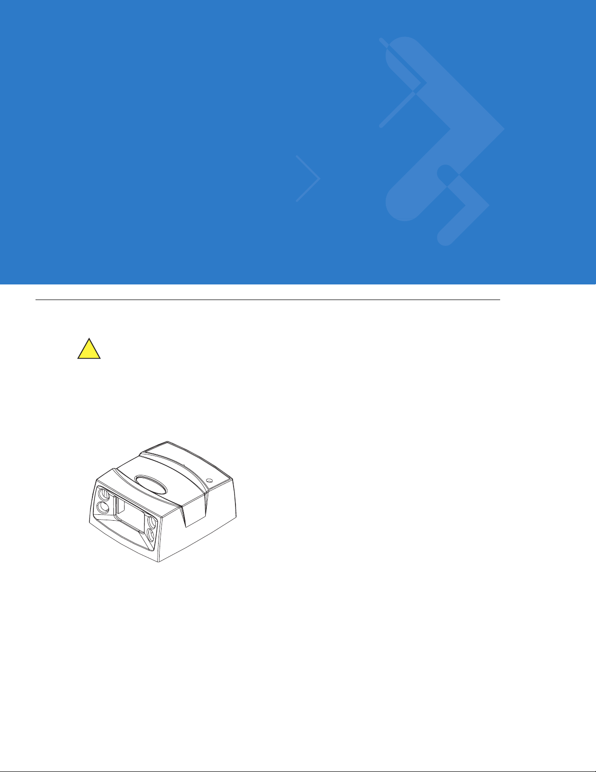
The Symbol MS440X fixed-mount imager is specifically designed for stand-alone applications, and OEM
applications such as kiosks. The imager is extremely compact, provides easy and flexible integration of bar code
imaging into a host device, and of fers high-performance imaging on 1-D and 2-D bar codes. The Symbol MS440X
is ideal for medical instruments and manufacturing applications.
hazardous laser light exposure.
Figure 1-1
This integration guide includes parameters and describes the th eory of operation, installation, specifications, and
configuration.
Symbol MS440X MiniScan Imager
Page 20

1 - 2 Symbol MS4404/MS4407 Integration Guide
Symbol MS440X Features
•
Stand-alone or OEM applications
•
Quick and easy integration for OEM devices
•
Excellent imaging performance on all 1-D and 2-D bar codes
•
RS-232 (Serial) or USB Interface
•
Direct part mark (DPM) support (DPM version only). Scan 2D symbols etched directly onto an item’ s surface
(via laser etching and dot peening) for permanent identification.
•
Easy programming and configuration
•
Flexible mounting options
•
LEDs indicating power status and successful decodes.
Typical Applications
Fixed Mount Standalone Applications
•
Clinical diagnostics
•
Medical instruments
•
Work st ations
•
Assembly lines.
OEM Applications
•
Kiosks / ATMs
•
Music listening stations
•
Medical instruments
•
Clinical diagnostics
•
Lottery terminals / gaming
•
Airline gate check-in.
Theory of Operation
During image capture:
1. The imager sensor array contained in the SE4400 captures the image of the bar code through the optical
system.
2. The PL4407 controls the SE4400 imager to obtain the best possible image quality.
3. The PL4407 transfers the decoded data or image data to the host system.
The result is a monochrome digital image similar to that of a digital came ra. The output from the SE4400 is byte wide
pixel data that is sent to the PL4407.
Page 21
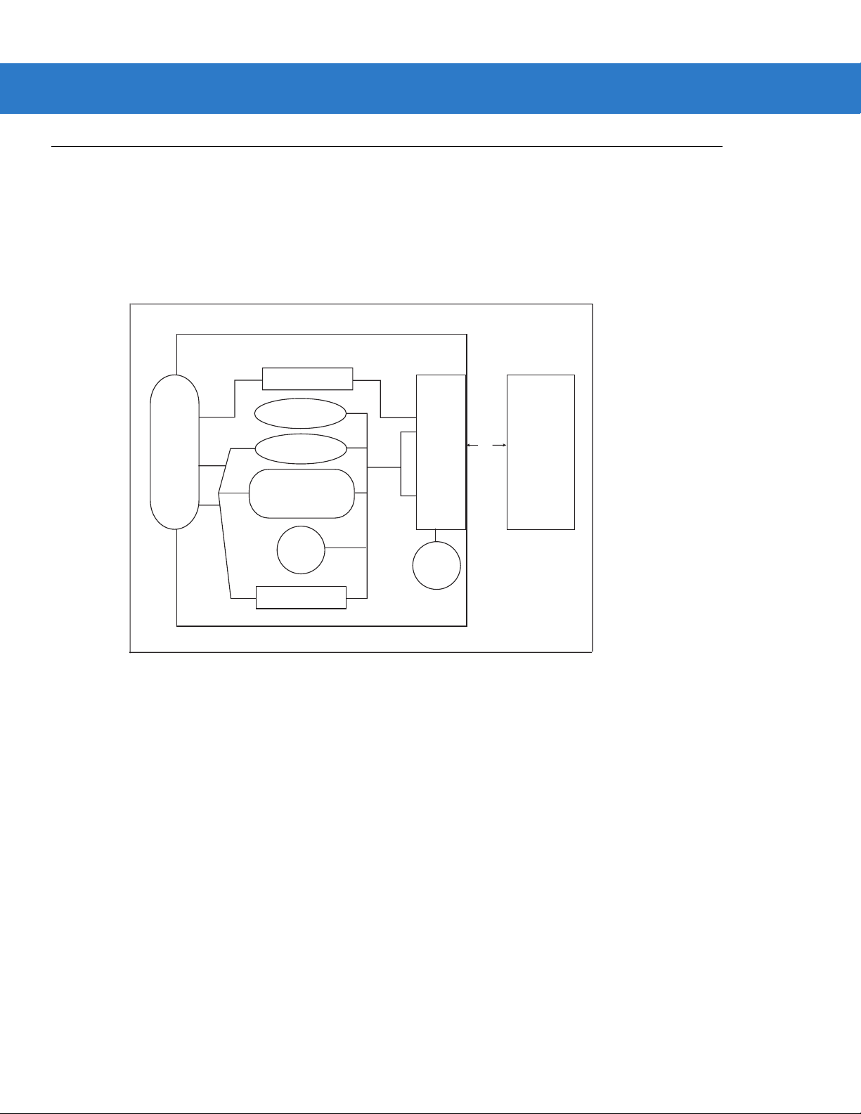
Block Diagrams
The MiniScan block diagrams illustrate the functional relationship of the MiniScan components. A detailed
description of each component in the block diagr ams is also pro vid ed .
Block Diagrams
Getting Started 1 - 3
Interface Board
Voltage Regulator
Figure 1-2
Beeper
DB9
External Beeper
Interface Circuit
Red/
Green
LED
External Trigger
Symbol MS4404 Block Diagram
PL4407
Decoder
LED
Illumina tion
flex
SE4400
(Imager)
Data
Acquisition
Engine
Page 22
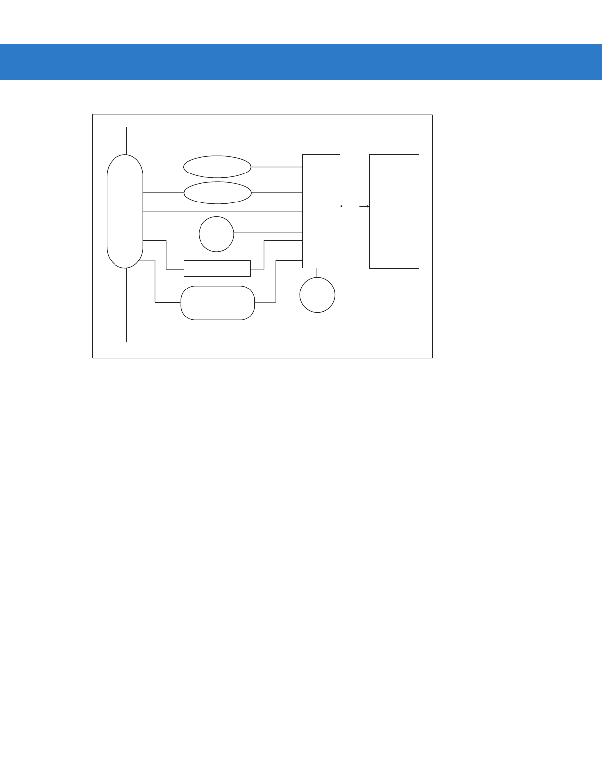
1 - 4 Symbol MS4404/MS4407 Integration Guide
.
Interface Board
Beeper
flex
SE4400
(Imager)
Data
Acquisition
Engine
Figure 1-3
External Beeper
DB9
Red/
Green
LED
External Trigger
Interface Circuit
Symbol MS4407 Block Diagram
PL4407
Decoder
LED
Illumina tion
Miniscan Block Diagram Descriptions
Imager Engine - The SE4400 engine provides digital images which can be transmitted to a decoder to decode a
bar code of any format supported by the decoding software. The engine utilizes laser aiming and an LED illumination
system, and can switch between two focus positions for extended working range or for mor e precise focusing in
high-density bar code decoding or digital picture taking.
Interface Board - The interface board adapts the imager engine's interface into usable signals and data for the host.
It also contains a beeper. LED illumination and red/green LED for audio/visual feedback, and provides for an
external trigger and external beeper.
The Symbol MS4404 interface board converts TTL level SSI signals to proper RS-232 levels fo r co nnectio n to an y
RS-232 compliant host, and the Symbol MS4407 interface board allows connection to logic level serial and USB
hosts.
Voltage Regulator (S ymbol MS4404 only) - The power supply allows the Symbol MS4404 to operate of the
extended input voltages of 5 - 12 Vdc.
DB9 - The DB9 connector provides an outlet for the various interface signals used between a MiniScan and the host.
It also maintains pin compatibility with MiniScan (MSXXXX) host cables.
Page 23

Getting Started 1 - 5
PL4407 Decoder
ARM9-Based Processor
The digital system is built on an ARM9 Harvard architecture core, 32 bit RISC engine with a five-stage pipeline. The
major features of the core are:
•
Programmable speed up to 150 MHz with an adjustable external bus speed up to 96 MHz.
•
16K instruction and data cache (64-way set associative).
•
Flexible internal bus architecture that supports DMA operations from any peripheral module to the core or to
another peripheral port including main memory.
•
Implementation of an enhanced Memory Management Unit (MMU).
Main Memory
The two available PL4407 microprocessor designs are:
•
PL4407-x100: 32-bit external bus interface to 8 MB of PC100-compliant SDRA M, class ified as Mo b ile
SDRAM due to its lower operating current and enhanced power-down modes; internally configured as
4 banks of 512 kb x 32 bits.
•
PL4407-x200: 32-bit external bus interface to 16 MB of Mobile SDRAM; internally configured as
4 banks of 1024 Kb x 32 bits.
Power Management (Symbol MS4404 Only)
NOTE This section does not apply to the USB interface. USB supports low power mode as defined by the USB
specification.
The Symbol MS4404 has two power modes:
•
Continuous Power
•
Low Power.
In Continuous Power mode, the Symbol MS4404 system is always running even when not in a decode session.
In Low Power mode (the default power mode), the Symbol MS4404 draw less current than when in Continuous
Power mode, and is more suitable for battery-powered applications. In this mode the Symbol MS4404 enter Low
Power mode whenever possible. The Symbol MS4404 must be awakened from Low Power mode before performing
any functions.
Page 24

1 - 6 Symbol MS4404/MS4407 Integration Guide
Table 1-1 describes how to put the Symbol MS4404 into Low Power mode; Table 1-2 describes how to awaken it.
Completely removing power from the Symbol MS4404 is not recommended; th is should not be necessary as in Lo w
Power mode the Symbol MS4404 consume very little power (see Table 1-1).
Table 1-1
Set the Power Mode parameter to Low
Power (see Power Mode on page 6-8).
Send the serial SLEEP command
(see the Simple Serial Interface (SSI)
Programmer Guide).
Note: All Wake Up signals (see T able 1-2) mu st be inactive to enter Low Power mode. Once the
Symbol MS4404 is awakened, at least 1 second (programmable time) must elapse before it
re-enters Low Power mode.
Table 1-2
AIM/WKUP* Low
TRIG* Low
CTS* Low
RXD Send 0x00
Placing the Symbol MS4404 into Low Power Mode
Action Behavior
The Symbol MS4404 enters Low Power mode
automatically whenever possible.
The Symbol MS4404 enters Low Power mode only
once, as soon as possible.
Waking Up the Symbol MS4404
Signal State to Wake Up
When the Symbol MS4404 is awakened, it remains awake for at least 1 second (programmable time) before
re-entering Low Power mode; the host must perform its first action within this time period.
Serial I/O
Simple Serial Interface (SSI) Protocol is a half-duplex asynchronous serial interface with two hardware handshaking
lines. The four SSI-specific interface signals are:
•
TXD - Transmitted Data
•
RXD - Received Data
•
RTS* - Request to Send
•
CTS* - Clear to Send
Signal names with the "*" modifier are asserted when at the positive logic 0 state (active low).
Signal names without the "*" modifier are asserted when at the positive logic 1 state (active high).
The TXD line transmits asynchronous serial data from the Symbol MS440X to the host.
The RXD line is used by the Symbol MS440X to receive asynchronous seria l data from the host. The SSI protocol
does not support full-duplex data transfers; dat a is either tran smitted or received by the Sym bol MS440X, but never
both simultaneously.
The RTS* and CTS* signals help coordinate data transfers between the Symbol MS440X and the host.
Page 25

Chapter 2 Installation
Overview
This chapter provides information on unpacking, mounting, and installing the MiniScan imager.
Unpacking
Remove the MiniScan from its packing and inspect for damag e. If the imager is dama ged, call Motorola Enterprise
Mobility Support on page xv.
KEEP THE PACKING. It is the approved shipping container and should be used if the equipment needs to be
returned for servicing.
Page 26
2 - 2 Symbol MS4404/MS4407 Integration Guide
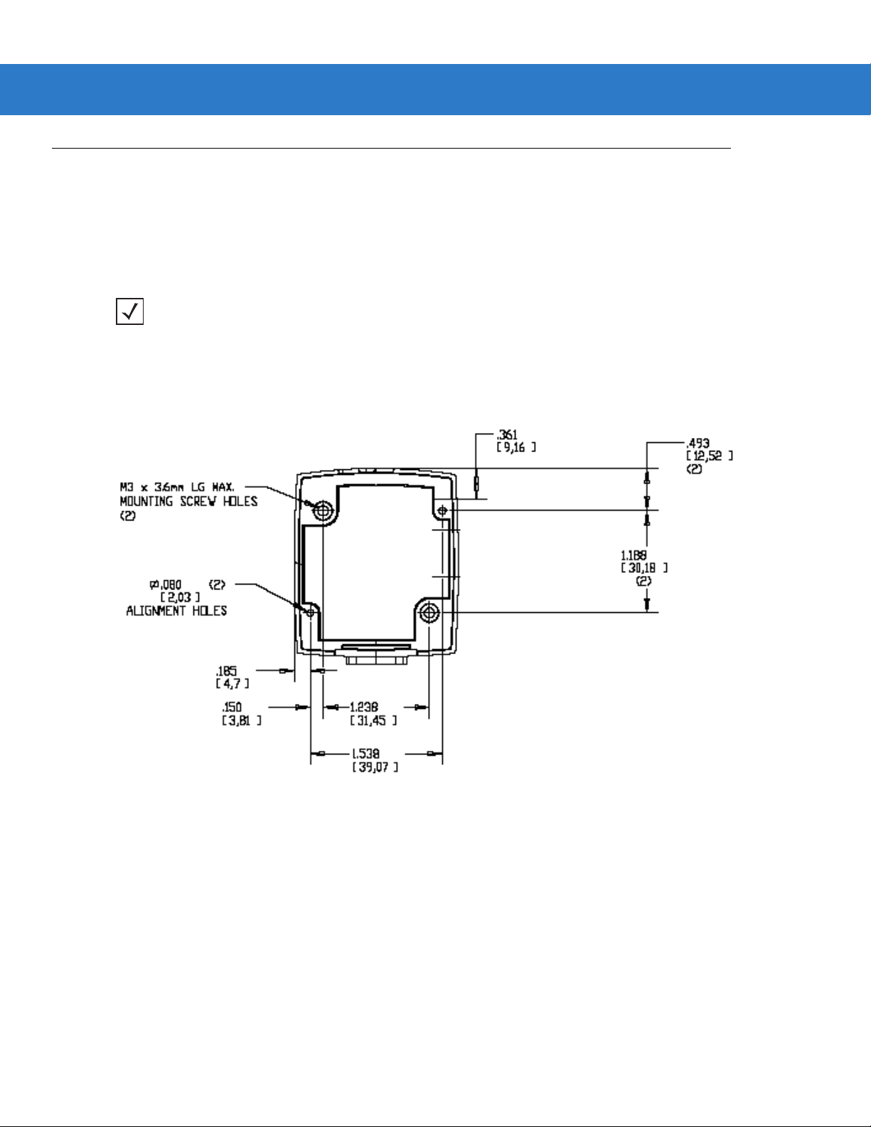
Mounting
There are two mounting holes (threaded inserts) on the bottom of the Symbol MS440X chassis.
The following figures provide mounting dimensions for the MiniScan housings. For a mounting template, see
Chapter 13, Mounting Template.
NOTE Use only non-magnetic M3x.5 screws with a maximum length of 3.6mm to mount the MiniScan imager
chassis.
Symbol MS440X Mounting Dimensions
Note: Dimensions are
in inches [mm]
Figure 2-1
Symbol MS440X Mounting Dimensions
Exit Window
Page 27
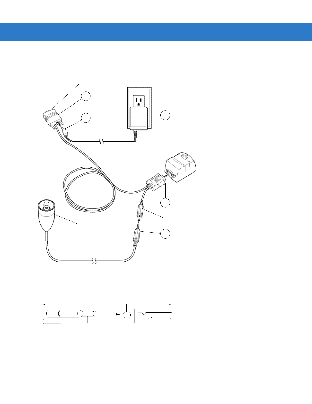
Connecting the MiniScan
1
2
2
3
3
To connect the MiniScan to the host, connect the imager cables in the order shown in Figure 2-2.
To Host
3
Getting Started 2 - 3
5
Trigger or Photo
Sensor (Optional)
4
1
Trigger Jack (Optional)
See Figure 2-3
2
Figure 2-2
1
Figure 2-3
Typical Connection Diagram
Male jack shown for reference
Note: Due to many variations of
jack and socket styles, identify
terminals as shown before
soldering leads.
Trigger Jack Connector Pins
Insertion
Direction
1 - Ground (Sleeve)
1 - Ground (Sleeve)
2 - Vcc (Middle Contact)
2 - Battery (Middle Contact)
3 - Trigger (Tip)
3 - Trigger (Tip)
Page 28
2 - 4 Symbol MS4404/MS4407 Integration Guide
Location and Positioning
The location and positioning guidelines provided do not consider unique application characteristics. It is
recommended that an opto-mechanical engineer perform an opto-mechanical analysis prior to integration.
NOTE Integrate the imager in an environment no more extreme than the product’s specification, where the
imager will not exceed its temperature range. For instance, do not mount the imager onto or next to a large
heat source. When placing the imager with another device, ensure there is proper convection or venting
for heat. Follow these suggestions to ensure product longevity, warranty, and overall satisfaction with the
imager.
Embedded Applications Requiring a Window
Use the following guidelines for applications that require a window in front of the MiniScan.
NOTE Motorola does not recommend placing an exit window in front of the MiniScan; however, the following
information is provided for applications that require such a window.
Window Material
NOTE The window placement and material recommendations that follow should be considered if the Symbol
MS440X is mounted within a product with its own window.
Many window materials that look perfectly clear can contain stresses and distortions that can reduce imager
performance. For this reason, optical glass or cell-cast acrylic with an anti-reflection coating is highly
recommended. Following is a description of acrylic, and CR-39, another popular window material. Table 2-1
outlines the suggested window properties.
CAUTION Consult an opto-mechanical engineer to recommend an appropriate window material and to
NOTE Do not use polycarbonate material.
Acrylic
When fabricated by cell-casting, acrylic has very good optical quality and low initial cost. However, protect the
surface from the environment as acrylic is susce pt ible to attack by chemicals, mechanical stresses, and UV light.
Acrylic has reasonably good impact resistance and can be ultrasonically welded.
CR-39
determine if coatings are appropriate for the specific application.
CR-39 is a thermal-setting plastic produced by the cell-casting process, and is commonly used in plastic eye glasses
lenses. CR-39 has excellent chemical and environmental resistance, including good surface hardness. Typically it
does not require hard-coating, but can be hard coated for severe environments. CR-39 has re asonably good impact
resistance and cannot be ultrasonically welded.
Page 29

Getting Started 2 - 5
Chemically Tempered Float Glass
Glass is a hard material which provides excellent scratch and abrasion resistance. However, unannealed glass is
brittle. Increasing flexibility strength with minimal optical distortion requires chemical tempering. Glass cannot be
ultrasonically welded and is difficult to cut into odd shapes.
Table 2-1
Material Clear cell-cast acrylic.
Spectral Transmission 85% minimum from 640 to 690 nanometers.
Thickness 0.059 ± 0.005
Wavefront Distortion (transmission) 0.2 wavelengths peak-to-valley maximum over any
Clear Aperture To extend to within 0.04 in. of the edges all around.
Surface Quality 60-20 scratch/dig
Coating Both sides to be anti-reflection coated to provide
Suggested Window Properties
Property Description
0.08 in. diameter within the clear aperture.
0.5% max reflectivity (each side) from 640 to 690
nanometers at nominal window tilt angle. Coatings
must comply with the hardness adherence
requirements of MIL-M-13508.
Window Coatings
Table 2-2 lists some e xit window manufacturers and anti-reflection coaters.
Anti-Reflection Coatings
Apply an anti-reflection coating to the inside and/or out side of the window to significantly reduce the amount of light
reflected off the window, back into the imager engine. The coating can also improve the range of acceptable window
positions and minimize performance degradation due to signal loss as the light pa sses through the window. Using
anti-reflection coatings on both the inside and outside of the window is high ly recommended.
Page 30

2 - 6 Symbol MS4404/MS4407 Integration Guide
Polysiloxane Coating
Polysiloxane type coatings are applied to plastic surfaces to improve the surface resistance to both scratch and
abrasion. They are usually applied by dipping, then air-drying in an oven with filtered hot air.
Table 2-2
Evaporated Coatings, Inc.
2365 Maryland Road
Willow Grove, PA 19090
(215) 659-3080
Fosta-Tek Optics, Inc.
320 Hamilton Street
Leominster, MA 01453
(978) 534-6511
Glasflex Corporation
4 Sterling Road
Sterling, NJ 07980
(908) 647-4100
Optical Polymers Int. (OPI)
110 West Main Street
Milford, CT 06460
(203) 882-9093
Polycast
70 Carlisle Place
Stamford, CT 06902
(800) 243-9002
Window Manufacturers and Coaters
Company Discipline Specifics
Anti-reflection coater Acrylic window supplier
Anti-reflection coater
Cell-caster, hard coater,
laser cutter
Cell-caster Acrylic exit window
CR-39 cell-caster, coater,
laser cutter
acrylic cell-caster, hard
coater, laser cutter
CR39 exit window
manufacturer
manufacturer
CR39 exit window
manufacturer
Acrylic exit window
manufacturer
TSP
2009 Glen Parkway
Batavia, OH 45103
(800) 277-9778
acrylic cell-caster, coater,
laser cutter
Acrylic exit window
manufacturer
Embedded Window Angle and Position
If a window is placed between the MiniScan and the item to be imaged, observe the following guidelines:
•
Window Clear Opening - Make the clear opening of the window large enou gh so that the entir e imager field
of view passes through the window. Cutting off any part of the field of view can degrade decode range
performance. Ensure that window placement relative to the MiniScan accounts for tolerances on all parts
involved in that assembly.
•
Window Angle - Angle the window at least 2o more than the tilt of the window on the imager ( see Table 2-3).
Further tilting the window is acceptable and decreases the possibility of a secondary reflection from that
window degrading the imager's perform an ce .
•
Optical Working Range - Adding a window can reduce the working range of the imager since there is a
signal loss when passing through window material. To minimize this reduction, use a special coating
described in Window Coatings on page 2-5. To understand the difference, test the imager in the desired
orientation and see if the difference affects imager performance.
Page 31

Getting Started 2 - 7
Table 2-3
Secondary Window Angles
MiniScan Model
MS4404/MS4407
MiniScan Exit
Window Angle from
Vertical
o
0.5
Minimum
Secondary Window
Angle from Vertical
(distance > 2 mm)
o
35
Notes:
Unless otherwise specified:
•
Dimensions are in inches, dimensions in [ ] are mm.
•
User mounting tolerances are not included.
Figure 2-4
Symbol MS440X Optical Path and Exit Window
Page 32

2 - 8 Symbol MS4404/MS4407 Integration Guide
Accessories
The following accessories are available for the MiniScan imager, and can be found in Symbol’s Solution Builder
(ordering guide).
Table 2-4
Power Supplies*
110V power supply, US 50-14000-008 50-14000-008R
220V power supply, Europe 50-14000-009 50-14000-009R
100V power supply, Asia 50-14000-010 50-14000-010R
264V Universal power supply
(also order cables below)
RS-232
Female DB9 with straight connector to RS-232
host (female DB9), with trigger jack and no
beeper
Female DB9 with straight connector to RS-232
host (female DB9), with trigger jack and beeper*
Female DB9 with straight connector to RS-232
host (female DB9)
MiniScan Imager Accessories
Accessory Standard Part Number ROHS Part Number
50-14001-001 50-14001-001R
DC line cord (power supply to imager) 50-16002-009 50-16002-009R
AC line cord (wall outlet to power supply) 23844-00-00 N/A
25-13227-XX 25-13227-XXR
25-13228-XX 25-13228-XXR
25-58918-XX 25-58918-XXR
Female DB9 with straight connector to RS-232
host (female DB9), with trigger jack and no
hardware handshaking
USB
Female DB9 with straight connector with trigger
jack and beeper to USB (Type A connector)
Female DB9 straight to USB 25-58926-XX 25-58926-XXR
Cable Adapters
Female 25 pin D, TxD on pin 2 50-12100-378 N/A
Female 25 pin D, TxD on pin 3 50-12100-377 N/A
Male 25 pin D, TxD on pin 2 50-12100-380 N/A
Male 25 pin D, TxD on pin 3 50-12100-379 N/A
*For power connection, this device must be connected to a limited power source.
Note: DO NOT use cables with an integrated beeper when operating at 12 VDC.
25-63736-XX 25-63736-XXR
25-58925-XX 25-58925-XXR
Page 33

Getting Started 2 - 9
Table 2-4
MiniScan Imager Accessories (Continued)
Accessory Standard Part Number ROHS Part Number
Optional Accessories
Push button trigger cable 25-04950-XX N/A
Photo sensor trigger cable 25-13176-XX N/A
Software
Software Developer's CD SW-60371-XX N/A
*For power connection, this device must be connected to a limited power source.
Note: DO NOT use cables with an integrated beeper when operating at 12 VDC.
Software Developer CD (Symbol MS4404 Only)
The Software Developer CD provides the software tools requir ed to integrate and communicate with the MiniScan
imagers, including:
•
Sample Windows® program with source code
•
DLL with source code for building user applications
•
ActiveX component (including help file) for easy integration into VisualBasic programs
•
Simple Serial Interface documentation.
With over 70 programmable paramete rs, you can configure MiniScan imagers using bar code menus, or through the
serial interface using Symbol’s Simple Serial Interface protocol.
For Windows
®
, DOS, and embedded system environments, the CD enables the user to take full advantage of the
imager’s features and obtain maximu m per for m an ce .
Page 34

2 - 10 Symbol MS4404/MS4407 Integration Guide
Page 35

Chapter 3 Imaging
Overview
This chapter provides information on aiming, illumination, focus control, data capture, beeper and decode LED
signals, supported symbologies and operating modes.
Aiming System
A 650 nm laser and a DOE generate a laser-aiming pattern which represents the imager's field of view throughout
its entire depth of field. The aiming subsystem uses a visible laser diode, a lens, and a dif fra ctive optical element to
generate the aiming pattern. The pattern's center cross hairs indicates the center of the field of view.
Figure 3-1
Figure 1-2. Aiming Pattern
Aiming Error
The aiming pattern is designed to eliminate divergence (parallax) between the aiming axis and the imaging axis.
This method provides an aiming axis parallel to the imaging axis, while minimizing the of fset b etween the two. See
Table 4-3 on page 4-6 and Table 4-4 on page 4-8 and for aiming element specifications.
Aiming Control
The aiming subsystem is under dynamic software control and is independent of the illumination subsystem.The
Symbol MS440X can capture images with both the aiming subsystem turned on (the ima ge of the aiming pa ttern is
captured in the digital image) and the aiming subsystem turned off.
Page 36

3 - 2 Symbol MS4404/MS4407 Integration Guide
Illumination System
An illumination subsystem, consisting of four red 635 nm LEDs, is provided to meet the image capture and
decoding requirements throughout the full range of ambient lighting (total darkness to full sunlight).
Illumination Control
The Symbol MS440X can capture images with the illumination subsystem turned on or off, accommodating images
that are close to the wavelength of the illumination. For example, since red LED illumination is used, it may be
desirable to shut off the illumination when capturing a printed image in red ink.
Focus Control
The Symbol MS440X has two focus positions controlled by an electromagnetic motor, which is under dynamic
software control and is independent of the illumination and aiming systems. The operating modes of the motor are:
•
Near Focus
•
Far Focus (default).
Imaging Tips
When imaging, ensure the symbol to be captured is within the decode range. See Location and Positioning on
page 2-4. Ensure the bar code is within the aiming pattern. The green decode LED lights and the imager beeps to
indicate a successful decode.
Capturing Data
Place the symbol in any orientation within the aiming pattern. Ensure the entire symb ol is within the rectangular
area formed by the brackets in the aiming pattern. The red laser aiming pattern turns on to assist in aiming.
1D bar code symbol
2D bar code symbol
2D dot peen DPM symbol
Figure 3-2
Aiming Pattern
Imager Aiming Pattern: Bar Code Centered
Page 37

Imaging 3 - 3
Correct
Figure 3-3
Imager Aiming Pattern: Bar Code Not Centered
Beeper Signals
The BPR* output line is provided for user feedback, and provides 50 mA drive capability for an external beeper.
The Symbol MS440X's beeper ranges from 2.352 KHz to 2.963 KHz. The beeper output is a 50% duty cycle
square wave at maximum volume, 12.5% at low volume.
Table 3-1
Decode Middle Tone
Trigger is pulled No sound
System bootup Low Tone, Middle Tone, High Tone
Transmission error Four Low Tones
Snapshot started Low Tone
Snapshot completed Low Tone
Beeper Indications
Event Beeper Indication
Incorrect
Entry error Low Tone, High Tone
Parameter entered High Tone, Low Tone, High Tone, Low Tone
Defaults set High Tone, Low Tone, High Tone, Low Tone
Scanner expects a number High Ton e, Lo w Tone
No Decode message No Sound
Video mode is on No Sound
Video mode is off No Sound
Scanner wakeup No Sound
Page 38

3 - 4 Symbol MS4404/MS4407 Integration Guide
Supported Symbologies
Table 3-2 lists the bar code types supported by the imaging system. Each can be individually enabled or disabled.
Table 3-2
Bookland EAN Coupon Code GS1 DataBar
Codabar Data Matrix (ECC 200) UPC/EAN
Code 11 Discrete 2 of 5 UCC/EAN 128
Code 39 Interleaved 2 of 5 US Planet
Code 39 Full ASCII Maxicode US Postnet
Trioptic Code 39 MicroPDF417 UK Postal
Code 93 PDF417 Australian Postal
Code 128 MSI Plessey Japan Postal
Composite Codes QR Code Dutch Postal
Aztec (New in 2006)
Supported Symbologies
Operating Modes
The imaging system supports the following opera ting modes. See Operational Modes on page 7-4 for the bar codes
to change between modes.
•
Decode (default mode) - for decoding a bar code
•
Snapshot - for capturing an image
•
Video - provides a video of the subject
•
Snapshot with Viewfinder Mode - provides a video of the subject until a snapshot of the image is captured.
Page 39

Chapter 4 Symbol MS4404/MS4407
Specifications
Electrical Interface
Symbol MS4404 Electrical Interface
Figure 4-1
Symbol MS4404 MiniScan Connector
Page 40

4 - 2 Symbol MS4404/MS4407 Integration Guide
Table 4-1 lists the pin functions of the Symbol MS4404 interface.
Table 4-1
Pin No. Pin Name Type* Function
1 Trigger I Signals imager to begin decoding session.
2 TXD O Serial data transmit output. Drives the serial data receive
3 RXD I Serial data receive input. Driven by the serial data transmit
4NC
5 Ground Power supply ground input and signal ground reference.
6 Power I 5.0 VDC - 12 VDC ± 10%
7 CTS I Clear-to-send handshaking input line, used only in
8 RTS O Request-to-send handshaking output line, used only in
9 Beeper/Download I/O During normal operation this signal functions as an external
Symbol MS4404 True RS-232 Electrical Interface
input on the device communicating with the imager.
output on the device communicating with the imager.
conjunction with the RTS line. Optionally used by another
device to signal the imager to begin transmitting data.
conjunction with the CTS line. Optionally used by the imager
to signal another device that data is available to send.
beeper drive line. This signal can sink 50mA of current to
drive an external beeper, and is normally pulled up. This
signal is also used to begin Flash Download operation when
grounded externally during power up.
NC = No Connect (Do not connect this pin)
*I = Input O = Output
Page 41

Symbol MS4407 Electrical Interface
Symbol MS4404/MS4407 Specifications 4 - 3
Figure 4-2
Table 4-2 lists the pin functions of the Symbol MS4407 interface.
Table 4-2
Pin No. Pin Name Pin No. Pin Name
1 Trigger 1 Trigger
2 NC 2 TXD Output TTL Only
3 USB + 3 RXD Input TTL Only
4 Connect to Pin 8 4 NC
5 Ground 5 Ground
6 +5V Power 6 +5V Power
7 USB - 7 CTS Input TTL Only
8 Connect to Pin 4 8 RTS Output TTL Only
9 Beeper/Download 9 Beeper/Download
NC = No Connect (Do not connect this pin)
Symbol MS4407 MiniScan Connector
Symbol MS4407 USB and Serial Electrical Interface
USB Interface Serial Interface
Page 42

4 - 4 Symbol MS4404/MS4407 Integration Guide
Mechanical Drawings
Notes:
Unless otherwise specified:
•
Dimensions are in inches, dimensions in [ ] are mm.
•
User mounting tolerances are not included.
Figure 4-3
Symbol MS440X Mechanical Drawings - Part 1
Page 43

Symbol MS4404/MS4407 Specifications 4 - 5
Notes:
Unless otherwise specified:
•
Dimensions are in inches, dimensions in [ ] are mm.
•
User mounting tolerances are not included.
Figure 4-4
Symbol MS440X Mechanical Drawings - Part 2
Page 44

4 - 6 Symbol MS4404/MS4407 Integration Guide
Symbol MS4404 Technical Specifications
Table 4-3
Power Requirements
Aiming Element
Field of View
Focal Distance from Front of Engine
Illumination Element
Image File Formats BMP, TIFF, JPEG
Symbol MS4404 Technical Specifications at 23° C
Item Description
Input Voltage
Input Current
Visible Laser Diode (VLD)
VLD Power
Pattern Angle
Aiming Error
Horizontal
Vertical
Near Focus
Far Focus
Light Emitting Diode (LED) 635 nm ± 20 nm (Internal/External)
4.5 V (min) to 13.2 V (max)
5 V in presentation mode active scan with external illumination;
260 mA (max)
650 nm ± 5 nm
0.7 mW Maximum
30.0º horizontal, 22.5º vertical
Total aiming error is 6.0 mm offset (horizontal)
Maximum angular aiming error is 1.5º
33.2 degrees
24.5 degrees
5 inches
9 inches
Interface True RS-232
Optical Resolution (gray scale) 640 (H) x 480 (V) pixels
Pitch Angle ± 60º from normal (see Figure 4-5 on page 4-10 )
Roll 360º (see Figure 4-5 on page 4-10)
Skew To ler anc e ± 50º from normal (see Figure 4-5 on page 4-10)
Symbologies 1-D Symbologies 2-D Symbologies
UPC/EAN Maxicode
Code 128 PDF417
UCC.EAN128 DataMatrix
GS1 DataBar QRCode
Code 39
Code 93 Postal Codes
I 2 of 5 US Postnet
Discrete 2 of 5 US Planet
Codabar U K Postal
MSI Australian Postal
Japan Postal
Note: Environmental and/or tolerance parameters are not cumulative. A thermal analysis
is recommended if the application is subject to an extreme temperature environment.
Page 45

Symbol MS4404/MS4407 Specifications 4 - 7
Table 4-3
Ambient Light Immunity
Humidity
Shock 2000 ± 5% G
Drop Multiple 30 in. (76.2 cm) drops to concrete
Temperature
Electrical Safety (pending) ETL, VDE
Laser Classification (aiming element) It is intended for use in CDRH Class 2/IEC Class 1 devices.
Radiated Emissions (pending) FCC Part 15 Class B, CISPIR22 Class B
Height 0.99 in. (25.2 mm) maximum
Width 1.91 in. (30.2 mm) maximum
Symbol MS4404 Technical Specifications at 23° C (Continued)
Item Description
Sunlight Total darkness to 9,000 ft. candles (96,900 lux)
Operating
Storage
Operating
Storage
95% RH, non-condensing at 50º C
85% RH, non-condensing at 70º C
-4º to 122º F (-20º to 50º C) (50% duty cycle)
-40º to 158º F (-40º to 70º C)
Depth 2.18 in. (55.4 mm) maximum
Weight 1.8 oz. (51.0 grams)
Interface 9-pin Male D-sub supports all interfaces
Note: Environmental and/or tolerance parameters are not cumulative. A thermal analysis
is recommended if the application is subject to an extreme temperature environment.
Page 46

4 - 8 Symbol MS4404/MS4407 Integration Guide
Symbol MS4407 Imager Technical Specifications
Table 4-4
Power Requirements
Aiming Element
Field of View
Focal Distance from Front of Engine
Illumination Element
Image File Formats BMP, TIFF, JPEG
Symbol MS4407 Technical Specifications at 23° C
Item Description
Input Voltage
Input Current
Visible Laser Diode (VLD)
VLD Power
Pattern Angle
Aiming Error
Horizontal
Vertical
Near Focus
Far Focus
Light Emitting Diode (LED) 635 nm ± 20 nm (Internal/External)
4.5 V (min) to 5.5 V (max)
5 V in presentation mode active scan with external illumination;
245 mA (max)
650 nm ± 5 nm
0.7 mW Maximum
30.0º horizontal, 22.5º vertical
Total aiming error is 6.0 mm offset (horizontal)
Maximum angular aiming error is 1.5º
33.2 degrees
24.5 degrees
5 inches
9 inches
Interface 0 - 5 V Serial (TTL 232), USB1.1
Optical Resolution (gray scale) 640 (H) x 480 (V) pixels
Pitch Angle ± 60º from normal (see Figure 4-5 on page 4-10 )
Roll 360º (see Figure 4-5 on page 4-10)
Skew To ler anc e ± 50º from normal (see Figure 4-5 on page 4-10)
Note: Environmental and/or tolerance parameters are not cumulative. A thermal analysis
is recommended if the application is subject to an extreme temperature environment.
Page 47

Symbol MS4404/MS4407 Specifications 4 - 9
Table 4-4
Symbologies 1-D Symbologies 2-D Symbologies
Ambient Light Immunity
Humidity
Symbol MS4407 Technical Specifications at 23° C (Continued)
Item Description
UPC/EAN PDF417
Code 128 MicroPDF417
UCC.EAN128 DataMatrix
ISBT 128 Maxico de
Code 39 QRCode
Trioptic Code 39 Aztec
Code 93
Code 11 Postal Codes
I 2 of 5 US Postnet
Discrete 2 of 5 US Planet
Codabar UK Postal
MS Japan Postal
GS1 DataBar Australian Postal
Inverse 1DI Dutch Postal
Composite Codes 4State Postal
DPM
(DPM version only).
Sunlight Total darkness to 9,000 ft. candles (96,900 lux)
Operating
Storage
95% RH, non-condensing at 50º C
85% RH, non-condensing at 70º C
Shock 2000 ± 5% G
Drop Multiple 30 in. (76.2 cm) drops to concrete
Temperature
Operating
Storage
Electrical Safety (pending) ETL, VDE
Laser Classification (aiming Element) It is intended for use in CDRH Class 2/IEC Class 1 devices.
Radiated Emissions (pending) FCC Part 15 Class B, CISPIR22 Class B
Height 0.99 in. (25.2 mm) maximum
Width 1.91 in. (30.2 mm) maximum
Depth 2.18 in. (55.4 mm) maximum
Weight 1.8 oz. (51.0 grams)
Interface 9-pin Male D-sub supports all interfaces
Note: Environmental and/or tolerance parameters are not cumulative. A thermal analysis
is recommended if the application is subject to an extreme temperature environment.
-4º to 122º F (-20º to 50º C) (50% duty cycle)
-40º to 158º F (-40º to 70º C)
Page 48

4 - 10 Symbol MS4404/MS4407 Integration Guide
Skew, Pitch and Roll
Measured on a 20 mil Code 39 symbol at a distance of 10 inches. Tolerance is reduced at extreme ends of the
working range.
Skew Pitch
+ 50° from normal
60° from normal
+
Roll
360°
Note: Tolerances are
reduced at extreme ends
of the working range.
Figure 4-5
Skew, Pitch and Roll
Page 49

Decode Zones
Standard Near Focus
The decode zone for the Near Focus Symbol MS440X is sh own in Figur e 4-6. Typical values are shown. Ta ble 4-5
lists the typical and guaranteed di st ances for sele cted ba r code de nsities. The minimum ele ment wid th (o r “sym bol
density”) is the width in mils of the narrowest element (bar or space) in the symbol.
Note: Typical performance at 73°F (23°C)
on high quality symbols in normal room light.
Vcc = 5.0 Vdc
Symbol MS4404/MS4407 Specifications 4 - 11
cm
in.
3.5
8.9
W
i
d
1.75
4.4
t
h
MS440X
In.
cm
* Minimum distance determined by symbol length and scan angle.
Figure 4-6
2.7
2.2
2.0
*
*
0
0
2
5.1
5 mil
6.67 mil PDF417
3.0
7.5 mil
10 mil PDF417
3.0
13 mil (100% UPC)
15 mil PDF417
468
10.2
5.5
5.25
6.0
6.0
7.0
7.0
20 mil
15.2
Depth of Field
Standard Near Focus Decode Zone
20.3
9.5
10
25.4
0
1.75
3.5
4.4
8.9
o
0
f
F
i
e
l
d
Page 50

4 - 12 Symbol MS4404/MS4407 Integration Guide
Table 4-5
Symbol Density/
Bar Code Type
5.0 mil
Code 39
6.67 mil
PDF417
7.5 mil
Code 39
10 mil
PDF417
13 mil
UPC-A
15 mil
PDF417
20 mil
Code 39
Standard Near Focus Decode Distances
Bar Code
Content/
Contrast
Note 2
ABCDEFGH
80% MRD
4 Col, 20 Rows
80% MRD
ABCDEF
80% MRD
3 Col, 17 Rows
80% MRD
012345678905
80% MRD
Typical Working
Ranges
Near Far Near Far
2.7 in
6.9 cm
3.0 in
7.62 cm
2.2 in
5.6 cm
3.0 in
7.6 cm
2.0 in
5.1 cm
80% MRD Note 1 7.0 in
123
Note 1 9.5 in
80% MRD
5.5 in
14.0 cm
5.25 in
13.3 cm
6.0 in
15.2 cm
6.0 in
15.2 cm
7.0 in
17.8 cm
17.8 cm
24.1 cm
Guaranteed Working
Ranges
4.0 in
10.2 cm
4.5 in
11.4 cm
3.5 in
8.9 cm
4.0 in
10.2 cm
3.0 in
7.6 cm
Note 1 6.0 in
Note 1 8.0 in
Notes:
1. Near distances are field-of-view (FOV) limited.
2. Contrast is measured as Mean Reflective Difference (MRD) at 670 nm.
3. Working range specifications at temperature = 23°C, pitch=15°, roll=0°,
skew=0°, photographic quality, ambient light ~30 ft-c, humidity 45-70% RH.
5.0 in
12.7 cm
5.0 in
12.7 cm
5.5 in
13.9 cm
5.5 in
13.9 cm
6.0 in
15.2 cm
15.2 cm
20.3 cm
Page 51

Symbol MS4404/MS4407 Specifications 4 - 13
Standard Far Focus
The decode zone for the Far Focus Symbol MS440X is shown in Figure 4-7. Typical values are shown. Table 4-6
lists the typical and guaranteed di st ances for sele cted ba r code de nsities. The minimum ele ment wid th (o r “sym bol
density”) is the width in mils of the narrowest element (bar or space) in the symbol.
Note: Typical performance at 73°F (23°C)
on high quality symbols in normal room light.
Vcc = 5.0 Vdc
in.
8
4
cm
20.3
10.2
W
i
d
t
h
MS440X
5 mil
7.0
5.5
7.5 mil
In.
cm
2.75
*
*
0
0
3.5
10 mil PDF417
5.0
13 mil (100% UPC)
15 mil PDF417
5
12.7 25.4
9.0
9.0
13.5
12.0
20 mil
10 15 20
38.1
Depth of Field
* Minimum distance determined by symbol length and scan angle.
Figure 4-7
Standard Far Focus Decode Zone
18.5
50.8
0
10.2
4
f
F
o
0
i
20.3
8
e
l
d
Page 52

4 - 14 Symbol MS4404/MS4407 Integration Guide
Table 4-6
Symbol Density/
Bar Code Type
5.0 mil
Code 39
6.67 mil
PDF417
7.5 mil
Code 39
10 mil
PDF417
13 mil
UPC-A
15 mil
PDF417
20 mil
Code 39
Standard Far Focus Decode Distances
Bar Code
Content/
Contrast
Note 2
ABCDEFGH
80% MRD
4 Col, 20 Rows
Typical Working
Near Far Near Far
5.5 in
13.9 cm
N/A N/A N/A N/A
80% MRD
ABCDEF
80% MRD
3 Col, 17 Rows
80% MRD
012345678905
80% MRD
3.5 in
8.9 cm
5.0 in
12.7 cm
2.75 in
6.9 cm
80% MRD Note 1 12.0 in
123
Note 1 18.5 in
80% MRD
Ranges
7.0 in
17.8 cm
9.0 in
22.9 cm
9.0 in
22.9 cm
13.5 in
34.3 cm
30.5 cm
46.9 cm
Guaranteed Working
Ranges
N/A N/A
5.5 in
14.0 cm
6.5 in
16.5 cm
3.0 in
7.6 cm
Note 1 11.0 in
Note 1 15.5 in
Notes:
1. Near distances are FOV limited.
2. Contrast is measured as Mean Reflective Difference (MRD) at 670 nm.
3. Working range specifications at temperature = 23°C, pitch=15°, roll=0°, skew=0°,
photographic quality, ambient light ~30 ft-c, humidity 45-70% RH.
7.0 in
17.8 cm
8.0 in
20.3 cm
11.5 in
29.2 cm
27.9 cm
39.4 cm
Page 53

Symbol MS4404/MS4407 Specifications 4 - 15
HD/DPM Near Focus
The decode zone for the Near Focus Symbol MS440X HD and DPM versions is shown in Figure 4-8. Typical
values are shown. Table 4-7 lists the typical and guaranteed distances for selected bar code densities. The
minimum element width (or “symbol density”) is the width in mils of the narrowest element (bar or space) in the
symbol.
in.
cm
3.0
1.5
7.6
3.8
W
i
d
t
h
Note: Typical performance at 73°F (23°C)
on high quality symbols in nor mal room light.
Vcc = 3.3V
MS440X
DPM
In.
cm
4 mil PDF417
2.4
1.7
6.67 mil PDF417
2.0
1.6
1.7*
*
*
0
0
1
2.5
10 mil PDF417
2.2
15 mil PDF417
2
10.2
3.2
5 mil
3.6
7.5 mil
13 mil (100% UPC)
20 mil
3
7.6
10.2
4.0
4.3
4.0
4.5
4
5
12.7
Depth of Field
* Minimum distance deter mined by symbol length and scan angle .
5.1
6
15.2
7
17.8
7.0
8
20.3
1.5
3.0
0
o
0
f
F
i
3.8
e
l
d
7.6
Figure 4-8
HD/DPM Near Focus Decode Zone
NOTE The decode zone performance for DPM shown above is based on controlled conditions and is to be used
as a guide only. Decoding is affected by mark quality, type, surface, and grade as well as ambient lighting
conditions.
Page 54

4 - 16 Symbol MS4404/MS4407 Integration Guide
Table 4-7
HD/DPM Near Focus Decode Distances
Symbol Density/
Bar Code Type
4.0 mil
PDF417
5.0 mil
Code 39
6.67 mil
PDF417
7.5 mil
Code 39
10 mil
PDF417
13 mil
UPC-A
15 mil
PDF417
20 mil
Code 39
Bar Code
Content/
Contrast
Note 2
80% MRD 2.4 in
ABCDEFGH
80% MRD
4 Col, 20 Rows
80% MRD
ABCDEF
80% MRD
3 Col, 17 Rows
80% MRD
012345678905
80% MRD
Typical Working Ranges
Near Far Near Far
3.2 in
6.10 cm
1.7 in
4.32 cm
2.0 in
5.08 cm
1.6 in
4.06 cm
Note 1
1.7 in
4.32 cm
2.2 in
5.59 cm
8.13 cm
4.0 in
10.16 cm
3.6 in
9.14 cm
4.3 in
10.92 cm
4.0 in
10.16 cm
5.1 in
12.95 cm
80% MRD Note 1 4.5 in
11.43 cm
123
80% MRD
Note 1 7.0 in
17.78 cm
Guaranteed Working
Ranges
Note 1 2.74 in
6.96 cm
2.29 in
5.82 cm
2.74 in
6.96 cm
2.54 in
6.45 cm
3.04 in
7.72 cm
2.94 in
7.47 cm
3.54 in
8.99 cm
Note 1 3.04 in
7.72 cm
Note 1 4.04 in
10.26 cm
Note 1 3.79 in
9.63 cm
Note 1 5.29 in
13.44 cm
Notes:
1. Near distances are field-of-view (FOV) limited.
2. Contrast is measured as Mean Reflective Difference (MRD) at 670 nm.
3. Working range specifications at temperature = 23°C, pitch=15°, roll=0°, skew=0°,
photographic quality, ambient light ~30 ft-c, humidity 45-70% RH.
Page 55

Symbol MS4404/MS4407 Specifications 4 - 17
HD/DPM Far Focus
The decode zone for the Far Focus Symbol MS440X HD and DPM ve rsions is shown in Figur e 4-9. Typical values
are shown. Table 4-8 lists the typical and guaranteed distances for selected bar code densities. The minimum
element width (or “symbol density”) is the width in mils of the narrowest element (bar or space) in the symbol.
Note: Typical performance at 73°F (23°C)
on high quality symbols in nor mal room light.
Vcc = 3.3V
MS440X
DPM
In.
cm
5 mil
3.5
6.67 mil PDF417
4.0
2.7
10 mil PDF417
3.8
2.5
2.7*
*
0
0
13 mil (100% UPC)
15 mil PDF417
3
7.6 15.2
7.5 mil
20 mil
6
7.0
7.1
9.0
9.0
10.5
10.2
912
22.9 30.5
Depth of Field
* Minimum distance deter mined by symbol length and scan angle .
14.5
15
38.1
in.
4
2
0
2
4
cm
10.2
5.1
5.1
10.2
W
i
d
t
h
o
0
f
F
i
e
l
d
Figure 4-9
NOTE The decode zone performance for DPM shown above is based on controlled conditions and is to be used
HD/DPM Far Focus Decode Zone
as a guide only. Decoding is affected by mark quality, type, surface, and grade as well as ambient lighting
conditions.
Page 56

4 - 18 Symbol MS4404/MS4407 Integration Guide
Table 4-8
HD/DPM Far Focus Decode Distances
Symbol Density/
Bar Code Type
4.0 mil
PDF417
5.0 mil
Code 39
6.67 mil
PDF417
7.5 mil
Code 39
10 mil
PDF417
13 mil
UPC-A
15 mil
PDF417
20 mil
Code 39
Bar Code
Content/
Contrast
Typical Working Ranges
Note 2
Near Far Near Far
Guaranteed Working
Ranges
80% MRD N/A N/A N/A N/A
ABCDEFGH
80% MRD
4 Col, 20 Rows
80% MRD
ABCDEF
80% MRD
3 Col, 17 Rows
80% MRD
012345678905
80% MRD
80% MRD 2.7 in
123
80% MRD
3.5 in
8.89 cm
4.0 in
10.16 cm
2.7 in
6.86 cm
3.8 in
9.65 cm
2.5 in
6.35 cm
Note 1
6.86 cm
7.0 in
17.78 cm
7.1 in
18.03 cm
9.0 in
22.86 cm
9.0 in
22.86 cm
10.5 in
26.67 cm
10.2 in
25.91 cm
Note 1 14.5 in
36.83 cm
4.79 in
12.17 cm
5.29 in
13.44 cm
4.04 in
10.26 cm
5.29 in
13.44 cm
3.54 in
8.99 cm
6.29 in
15.98 cm
5.79 in
14.71
7.29 in
18.52 cm
7.04 in
17.88 cm
8.29 in
21.06 cm
Note 1 7.79 in
19.79 cm
Note 1 11.54 in
29.31 cm
Notes:
1. Near distances are FOV limited.
2. Contrast is measured as Mean Reflective Difference (MRD) at 670 nm.
3. Working range specifications at temperature = 23°C, pitch=15°, roll=0°, skew=0°,
photographic quality, ambient light ~30 ft-c, humidity 45-70% RH.
Page 57

Chapter 5 Maintenance & Troubleshooting
Overview
The chapter provides information on maintenance and troubleshooting.
Maintenance
Cleaning the exit window is the only maintenance required. Do not allow any abrasive material to touch the window.
Clean the exit window with a damp cloth and, if necessary, a non-ammonia based detergent.
Page 58

5 - 2 Symbol MS4404/MS4407 Integration Guide
Troubleshooting
Problem Possible Cause Possible Solutions
No red LED or nothing
happens during a
capture attempt.
Imager cannot read the
bar code.
No power to the imager. Check the system power.
Confirm that the correct host interface
cable is used.
Connect the power supply.
Re-connect loose cables.
Interface/power cables are
loose.
Imager is not programmed for
the correct bar code type.
Incorrect communication
parameters.
Bar code symbol is
unreadable.
Inappropriately hot
environment.
Re-connect loose cables.
Ensure the imager is programmed to
read the type of bar code to be decoded.
Try capturing other ba r code(s) and other
bar code types.
Set the correct communication
parameters (baud rate, parity, stop bits,
etc.)
Check the symbol to ensure it is not
defaced. Try capturing similar symbols of
the same code type.
Remove the imager from the hot
environment, and allow it to cool down.
Laser activates, followed
by a beep sequence.
NOTE If after performing these checks the symbol still does not decode, contact the distributor or contact
Motorola Enterprise Mobility Support. See page xv for contact information.
Beeper is configured. Refe r to Beeper Signals on page 3-3 for
beeper indication descriptions.
Page 59

Chapter 6 User Preferences
Overview
This chapter describes each user preferen ce fea tu re and provides the programming bar codes necessary for
selecting these features.
Host Selection
Select a host type according to the pinout information in Tab l e 4- 2 on page 4-3 (connecting pins 4 and 8). The
default serial host for the Symbol MS4404 is SSI and the default USB host for the Symbol MS4407 is SNAPI with
Imaging, as these host types provide more flexibility during integration when configuring the unit via host
command.
Selecting other host configurations require using bar code menus and are not available via host programming.
These hosts do not support host triggering, and require a method to trigger the reader for initial configuration. Use
caution when selecting one of these hosts. Be sure to consider how setting up via bar code menu, which includes
providing a triggering method, can impact integratio n. See each host chapter for configuration o ptions for each h ost
type.
Changing Default Values
The imager ships with the settings shown in User Preferences Default Table on page 6-3 (also see Appendix A,
Standard Defaults for all host device and miscellaneous defaults). If the default values suit requirements,
programming is not necessary.
There are two ways to change a parameter value:
•
Capture the appropriate bar codes in this guide. These new values replace the standard default values in
memory.
•
For SSI and USB SNAPI hosts, send a “parameter send” command from the host system. Hexadecimal
parameter numbers are shown in this chapter below the parameter title, and options are shown in
parenthesis beneath the accompanying bar codes. See the Simple Serial In terface (SSI) Pr ogrammer Guide
for detailed instructions for changing parameter values using this method.
Page 60

6 - 2 Symbol MS4404/MS4407 Integration Guide
NOTE Most computer monitors allow capturing the bar codes directly on the screen. When capturing from the
screen, be sure to set the document magnification to a level where the bar code can be seen clearly, and
bars and/or spaces are not merging.
To return all features to default values, capture Set Default Parameter on page 6-3. Througho ut the pr ogramming
bar code menus, default values are indicated with asterisks (
*).
* Indicates Default
Imaging Sequence Examples
In most cases, capturing one bar code sets the parameter value. For example, to set the beeper tone to high,
capture the High Frequency (beeper tone) bar code listed under Beeper Tone on page 6-4. The imager issues a
fast warble beep signal and a good decode LED signal, signifying a successful parameter entry.
Other parameters, such as Presentation Mode Session T imeout, require capturing several bar codes. See these
parameter descriptions for this procedure.
Errors While Decoding
Unless otherwise specified, to correct an error during a decoding sequen ce, just re-capture the correct parameter.
*High Volume
(00h)
Feature/Option
Option Hex Value for programming
via SSI command
Page 61

User Preferences Parameter Defaults
Table 6-1 lists defaults for user preferences parameters. To change any parameter value, capture the appropriate
bar code(s) provided in User Preferences on page 6-3.
NOTE See Appendix A, Standard Defaults for all user preferences, hosts, symbologies, and miscellaneous
default parameters.
User Preferences 6 - 3
Table 6-1
User Preferences
Set Default Parameter All Defaults 6-3
Parameter Scanning ECh Enable 6-4
Beeper Tone 91h Medium 6-4
Beeper Volume 8Ch High 6-5
Trigger Mode 8Ah Presentation 6-6
Picklist Mode F0h 92h Disabled Always 6-7
Power Mode 80h Continuous On 6-8
Time Delay to Low Power Mode 92h 1.0 Sec 6-8
Decode Session Timeout 88h 9.9 Sec 6-9
Timeout Between Decodes, Same Symbol 89h 0.6 Sec 6-10
Beep After Good Decode 38h Enable 6-10
Presentation Mode Session Timeout F0h, 90h 2 Seconds 6-1 1
User Preferences Default Table
Parameter
Parameter
Number
Default Page Number
User Preferences
Set Default Parameter
Capture this bar code to return all parameters to the default values listed in Table A-1 on page A-1.
*Set All Defaults
Page 62

6 - 4 Symbol MS4404/MS4407 Integration Guide
Parameter Scanning
Parameter # ECh
To disable decoding of parameter bar codes, capture the Disable Parameter Sc annin g bar code below. Note that
you can still decode the Set Defaults parameter bar code. To enable decoding of parameter bar codes, capture
either Enable Parameter Scanning or Set All Defaults.
*Enable Parameter Scanning
(01h)
Disable Parameter Scanning
(00h)
Beeper Tone
Parameter # 91h
To select a decode beep frequency (tone), capture the Low Frequency, Medium Frequency, or High Frequency
bar code.
Low Frequency
(02h)
*Medium Frequency
(Optimum Setting)
(01h)
High Frequency
(00h)
Page 63

User Preferences 6 - 5
Beeper Volume
Parameter # 8Ch
To select a beeper volume, capture the Low Volume, Medium Volume, or High Volume bar code.
Low Volume
(02h)
Medium Volume
(01h)
*High Volume
(00h)
Page 64

6 - 6 Symbol MS4404/MS4407 Integration Guide
Trigger Mode
Parameter # 8Ah
•
Level - A trigger event activates decode processing, which continues until the trigger event ends, a valid
decode, or the decode session time-out is reached.
•
Presentation Mode - When the Symbol MS440X detects an object in its field of view it triggers and attempt
to decode. The range of object detection does not vary under normal lighting conditions. This applies to
decode mode only. In this mode the unit does not enter its sleep state.
•
Host - A host command issues the triggering signal. The Symbol MS440X interprets a trigger pull as a level
triggering option.
Level
(00h)
Host
(08h)
*Presentation Mode
(07h)
Page 65

User Preferences 6 - 7
Picklist Mode
Parameter # F0h 92h
Picklist mode enables the imager to decode only bar codes that are aligned und er the laser crosshair. Select one of
the following picklist modes for the imager:
•
Disabled Always (default) - Picklist mode is always disabled.
•
Enabled Out of Scanstand - Picklist mode is enabled when the imager is out of Scanstand mode and
disabled when the imager is in Scanstand mode.
•
Enabled Always- Picklist mode is always enabled.
*Disabled Always
(00h)
Enabled Always
(02h)
Enabled Out of Scanstand
(01h)
Page 66

6 - 8 Symbol MS4404/MS4407 Integration Guide
Power Mode
Parameter # 80h
This parameter determines whether or not power remains on after a decode attempt. In low power mode, the
imager enters into a low power consumption mode to preserve battery life after each decode attempt. In
continuous power mode, power remains on after each decode attempt.
*Continuous On
(00h)
Low Power Mode
(01h)
Time Delay to Low Power Mode
Parameter # 92h
This parameter sets the time the imager remains active after decoding. The imager wakes upon trigger pull or
when the host attempts to communicate with the imager.
NOTE This parameter only applies when Power Mode is set to Low Power.
To program a different value for this parameter than those provided below, see the Simple Serial Interface
(SSI) Programmer Guide.
*1 Second
(11h)
5 Seconds
(15h)
Page 67

Time Delay to Low Power Mode (continued)
1 Minute
(21h)
User Preferences 6 - 9
5 Minutes
(25h)
15 Minutes
(2Bh)
1 Hour
(31h)
Decode Session Timeout
Parameter # 88h
This parameter sets the maximum time decode pr ocessing co ntinues dur ing a decod e attempt. It is pro grammable
in 0.1 second increments from 0.5 to 9.9 seconds. The default timeout is 9.9 seconds.
To set a Dec ode Sessio n Timeout, capture the ba r cod e belo w. Next, capture two numeric bar codes from
Appendix D, Numeric Bar Codes that correspond to the desired on time. Single digit numbers must have a lea ding
zero. For example, to set a Decode Session Timeout of 0.5 seconds, capture the bar code below, then capture the
0 and 5 bar codes. To correct an error or change the selection, capture Cancel on page D-3.
Decode Session Timeout
Page 68

6 - 10 Symbol MS4404/MS4407 Integration Guide
Timeout Between Decodes, Same Symbol
Parameter # 89h
This option is used in presentation mode to prevent multiple reads of a symbol left in the Symbol MS440X field of
view. The timeout begins when the symbol is removed from the field of view. It is programmable in 0.1 second
increments from 0.0 to 9.9 seconds. The default interval is 0.6 seconds.
To select the timeout between decodes for the same symbol, capture the bar code below , then capture two numer ic
bar codes from Appendix D, Numeric Bar Codes that correspond to the desired interval, in 0.1 second increments.
Beep After Good Decode
Parameter # 38h
Timeout Between Decodes, Same Symbol
Capture a bar code below to select whether or not the imager issues a be ep signal after a good de code. If selecting
Do Not Beep After Good Decode, beeper signals are issued during parameter menu imaging and to indicate
error conditions.
*Beep After Good Decode
(Enable)
(01h)
Do Not Beep After Good Decode
(Disable)
(00h)
Page 69

User Preferences 6 - 11
Presentation Mode Session Timeout
Parameter # F0h, 90h
To set the duration of the attempt to decode a bar code detected in presentation mode, capture the bar co de below.
Next, capture three numeric bar codes from Appendix D, Numeric Bar Codes to select a value between 1 and 255
that represents tenths of a second. Single digit numbers must have a leading zero. For example, to set 0.5
seconds, capture the bar code below, then capture the 0, 0, 5 bar codes. To correct an error or change the
selection, capture Cancel on page D-3. The default value is 2 seconds.
Presentation Mode Session Timeout
Page 70

6 - 12 Symbol MS4404/MS4407 Integration Guide
Page 71

Chapter 7 Imager Preferences
Overview
This chapter describes imager preference features and provides the programming bar codes for selecting these
features.
The imager ships with the settings shown in the Imager Preferen ces Default Table on page 7-2 (also see Appendix
A, Standard Defaults for all host device and miscellaneous defaults). If the default values suit requirements,
programming is not necessary.
There are two ways to change a parameter value:
•
Capture the appropriate bar codes in this guide. These new values replace the standard default values in
memory.
•
For SSI and USB SNAPI hosts, send a “parameter send” command from the host system. Hexadecimal
parameter numbers are shown in this chapter below the parameter title, and options are shown in
parenthesis beneath the accompanying bar codes. See the Simple Serial In terface (SSI) Pr ogrammer Guide
for detailed instructions for changing parameter values using this method.
NOTE Most computer monitors allow capturing the bar codes directly on the screen. When capturing from the
screen, be sure to set the document magnification to a level where the bar code can be seen clearly, and
bars and/or spaces are not merging.
Select a host type (see each host chapter for specific host information) after the power-up beep signal activates.
This is only necessary upon the first power-up when connected to a new host.
To return all features to default values, capture *Set All Defaults on page 6-3. Throughout the programming bar
code menus, default values are indicated with asterisks (
* Indicates Default
*Enable Decode Aiming Pattern
(02h)
*).
Feature/Option
Option Hex Value for
programming via SSI command
Page 72

7 - 2 Symbol MS4404/MS4407 Integration Guide
Imaging Sequence Examples
In most cases capturing one bar code sets the parameter value. For example, to disable the decode aiming
pattern, capture the Disable Decode Aiming Pattern bar code listed under Decode Aimi ng Pattern on page 7-7.
For systems that use a beeper and LED, a fast warble beep sounds and the LED lights, signifying a successful
parameter entry.
Other parameters, such as Crop to Pixel Address, require capturing several bar codes. See these parameter
descriptions for this procedure.
Errors While Imaging
Unless otherwise specified, to correct an error during an imaging sequence, just re-capture the correct parameter.
Imager Preferences Parameter Defaults
Table 7-1 lists defaults for imager preferences parameters. To change any option, capture the appropriate bar
code(s) provided in Imager Preferences on page 7-4.
NOTE See Appendix A, Standard Defaults for all user preferences, hosts, symbologies, and miscellaneous
default parameters.
Table 7-1
Imaging Options
Focus Mode F0h A6h Far Focus
Decoding Autoexposure F0h 29h Enable 7-6
Decoding Illumination F0h 2Ah Enable 7-6
Decode Aiming Pattern F0h 32h Enable 7-7
DPM Scanning F1h 09h Enable
Image Capture Autoexposure F0h 68h Enable 7-9
Image Capture Illumination F0h 69h Enable 7-9
Imager Preferences Default Table
Parameter Parameter Number Default Page Number
Note: The default value
for DPM digital scanners
is Near Focus.
7-5
7-8
Gain F4h F0h A7h 100 7-10
Exposure Time F4h F0h 38h 10 ms 7-11
LED Illumination F0h ADh External LED Illumination 7-12
Snapshot Mode Timeout F0h 43h 0 (30 seconds) 7-12
Page 73

Imager Preferences 7 - 3
Table 7-1
Snapshot Aiming Pattern F0h 2Ch Enable 7-13
Image Cropping F0h 2Dh Disable 7-13
Crop to Pixel Addresses F4h F0h 3Bh;
Image Resolution F0h 2Eh Full 7-15
JPEG Image Options F0h 2Bh Quality 7-16
JPEG Quality Value F0h 31h 65 7-16
JPEG Size V alue F0h 33h 40 (41K) 7-16
Image File Format Selection F0h 30h JPEG 7-17
Bits per Pixel (BPP) F0h 2Fh 8 BPP 7-17
Signature Capture 5Dh Disable 7-18
Signature Capture Image File Format
Selection
Imager Preferences Default Table (Continued)
Parameter Parameter Number Default Page Number
0 top, 0 left, 479 bottom,
F4h F0h 3Ch;
F4h F0h 3Dh;
F4h F0h 3Eh
F0h 39h JPEG 7-19
639 right
7-14
Signature Capture Bits per Pixel (BPP) F0h 3Ah 8 BPP 7-20
Signature Capture Width F4h F0h 6Eh 400 7-20
Signature Capture Height F4h F0h 6Fh 100 7-21
Signature Capture JPEG Quality F0h A5h 65 7-21
Video View Finder F0h 44h Disable 7-21
Target Video Frame Size F0h 48h 2200 bytes 7-22
Video View Finder Image Size F0h 49h 1700 bytes 7-22
Page 74

7 - 4 Symbol MS4404/MS4407 Integration Guide
Imager Preferences
The parameters in this chapter control image capture characteristics. Image capture occurs in all modes of
operation, including decode, video, and snapshot.
Operational Modes
The imager has three modes of operation:
•
Decode Mode
•
Snapshot Mode
• Snapshot with Viewfinder Mode
•
Video Mode.
Decode Mode
By default, upon a trigger event, the imager attempts to locate and decode enabled bar codes within its field of
view. The imager remains in this mode as long as the trigger is active or until a bar code is decoded.
Snapshot Mode
Use Snapshot Mode to capture a high-quality image and transmit it to the host. T o temporarily enter this mode
capture the Snapshot Mode bar code. While in this mode the imager blinks the green LED at 1-se cond intervals to
indicate it is not in standard operating (decode) mode.
In Snapshot Mode, the imager turns on the laser aiming pattern to highlight the area to be captured in the image.
The next trigger event instructs the imager to capture a high quality image and transmit it to the host. A short time
may pass (less than 2 seconds) between when the trigger is activated and the image is captured as the imager
adjusts to the lighting conditions. Hold the imager steady until the image is captured, denoted by a single beep.
If a trigger event is not activated within the Snapshot Mode Timeout period, the imager returns to Decode Mode.
Use Snapshot Mode Timeout on page 7-12 to adjust this timeout period. The default timeout period is 30 seconds.
To disable the laser aiming pattern during Snapshot Mode, see Snapshot Aiming Pattern on page 7-13.
Use Video View Finder on page 7-21 to enable Snapshot with Viewfinder Mode. In this mode the imager
behaves as a video camera until the trigger is active, at which time a Snapshot is performed as described above.
Page 75

Imager Preferences 7 - 5
Video Mode
In this mode the imager behaves as a video camera as long as the trigger is active. When the trigger is released,
the imager returns to Decode Mode. Capture this bar code to temporarily enter Video Capture Mode.
Snapshot Mode
Video Mode
Focus Mode
Parameter # F0h, A6h
Select the focus mode to control the working range of the imager. If Far Focus is selected, the imager is optimized
to read at its far position. With Near Focus, the imager is optimized to read at its near position.
*Far Focus
(00h)
Near Focus
(01h)
NOTE The default value for DPM digital scanners is Near Focus.
Page 76

7 - 6 Symbol MS4404/MS4407 Integration Guide
Decoding Autoexposure
Parameter # F0h,29h
Select Enable Decoding Autoexposure to allow the imager to control gain settings and exposure (integration)
time to best capture an image for the selected operation mode.
Select Disable Decoding Autoexposure to manually adjust the gain and exposure time (see Gain and Exposure
Time on the following pages). This option is only recommended for advanced users with difficult image capture
situations.
*Enable Decoding Autoexposure
(01h)
Disable Decoding Autoexposure
(00h)
Decoding Illumination
Parameter # F0h, 2Ah
Selecting Enable Illumination causes the imager to flash illumination on every image capture to aid decoding.
Select Disable Illumination to prevent the imager from using decoding illumination.
Enabling illumination usually results in superior images. The effectiveness of the illumination decreases as the
distance to the target increases.
*Enable Decoding Illumination
(01h)
Disable Decoding Illumination
(00h)
Page 77

Imager Preferences 7 - 7
Decode Aiming Pattern
Parameter # F0h, 32h
This parameter only applies when in Decode Mode. Select Enable Decode Aiming Pattern to project the aiming
pattern during bar code capture, or Disable Decode Aiming Pattern to turn the aiming pattern off.
*Enable Decode Aiming Pattern
(02h)
Disable Decode Aiming Pattern
(00h)
Page 78

7 - 8 Symbol MS4404/MS4407 Integration Guide
DPM Scanning
Parameter # F1h, 09h
Unlike bar codes that are typically printed on labels, a direct p art mark (DPM) is a symb ol that is marked directly on
an item’s surface for permanent identification. These symbols are marked using methods such as laser etching
and dot peening (see Figure 3-2 on page 3- 2 for an example of a dot peen symbol). The DS3407-DP (DPM) dig ital
reader scans these types of symbols.
NOTE When the DS3407-DP digital scanner is DPM enabled, the digital scanner reads all symbols including
DPM, 1D, PDF417, etc. If DPM reading is not required, scan Disable DPM Scanning to ensure optimum
scanner performance.
If you enable DPM Scanning, disable Picklist Mode on page 6-7 when scanning a DPM bar code.
Picklist performance is not guaranteed for DPM bar codes.
Also, if you enable DPM Scanning, the scanner behaves as if the DataMatrix Inverse Autodetect setting
is selected. When you disable DPM Scanning, the previous (user-selected) DataMatrix Inverse setting
remains in effect. SeeData Matrix Inverse on page 11-68.
To ensure the DS3407-DP digital scanner is programmed for DPM reading:
1. The DS3407-DP digital scanner can not r ead ce rtain bar codes in near field. To ensure the digital scanner can
read all bar codes, scan Far Focus on page 7-5.
2. If DPM scanning was disabled in the DS3407-DP digital scanner, scan Enable DPM Scanning (below).
3. Before scanning a DPM bar code, ensure that Data Matrix on page 11-68 is enabled.
*Enable DPM Scanning
(01h)
Disable DPM Scanning
(00h)
Page 79

Imager Preferences 7 - 9
Image Capture Autoexposure
Parameter # F0h, 68h
Select Enable Autoexposure to allow the imager to control gain settings and exposure (integration) time to best
capture an image for the selected operation mode.
Select Disable Autoexposure to manually adjust the gain and exposure time (see Gain and Exposure Time on the
following pages). This option is only recommended for advanced users with difficult image capture situations.
*Enable Image Capture Autoexposure
(01h)
Disable Image Capture Autoexposure
(00h)
Image Capture Illumination
Parameter # F0h, 69h
Selecting Enable Image Capture Illumination causes th e imag er to flash on every image captur e. Select Disa ble
Illumination to prevent the imager from using artificial illumination.
Enabling illumination usually results in superior images. The effectiveness of the illumination decreases as the
distance to the target increases.
*Enable Image Capture Illumination
(01h)
Disable Image Capture Illumination
(00h)
Page 80

7 - 10 Symbol MS4404/MS4407 Integration Guide
Gain
Parameter # F4h, F0h, A7h
This parameter only applies when Decoding or Image Capture Autoexposure is disabled. Gain is a means of
amplifying the raw image data before it is converted into 256 grayscale values. Increasing the gain increases
brightness and contrast, but also increases no ise (un desir ed electrical fluctuations in the image) which makes the
image less attractive and/or harder to decode.
To set the manual gain, capture the bar code below followed by 3 bar codes from Appendix D, Numeric Bar Codes,
in the range of 79 to 127, representing the value. The default is 100.
Set Gain
Page 81

Imager Preferences 7 - 11
Exposure Time
Parameter # F4h, F0h, 38h
This parameter is only available when Image Capture Autoexposure is disabled. Exposure Time controls the
amount of time the CCD is allowed to collect light, much like the shutter speed for a camera. Generally, the brighter
the environment, the lower the exposure ti me . Set the m an ual exposure time to one of the following values: 5 ms,
10 ms, 15 ms, 20 ms, 25 ms, or 30 ms. Increasing the exposure time past 20 ms in a handheld application
increases the risk of blurring the image due to hand jitter.
5 ms
(004Fh)
15 ms
(00ECh)
25 ms
(018Ah)
*10 ms
(009Dh)
20 ms
(013Bh)
30 ms
(01D8h)
Page 82

7 - 12 Symbol MS4404/MS4407 Integration Guide
LED Illumination
Parameter # F0h, ADh
Select whether to use internal LED illumination (provided by the Symbol MS440X), external illumination (provided
outside the Symbol MS440X), or both.
This parameter only applies for decoding if Decoding Illumination on page 7-6 is enabled, or for image capture if
Image Capture Illumination on page 7-9 is enabled. If Decoding Illumination or Image Capture Illumination is
disabled, all illumination is off for that mode, regardless of this LED Illumination setting.
Internal Illumination
(00h)
*External Illumination
(01h)
Internal and External Illumination
(02h)
Snapshot Mode Timeout
Parameter # F0h, 43h
This parameter sets the amount of time the imager remains in Snapshot Mode. The imager exits Snapshot Mode
upon a trigger event, or when the Snapshot Mode Timeout elapses. To set this timeout value, capture the bar code
below followed by a bar code from Appendix D, Numeric Bar Codes. The default value is 0 which represents 30
seconds; values increment by 30. For example, 1 = 60 seconds, 2 = 90 seconds, etc.
Snapshot Mode Timeout
Page 83

Imager Preferences 7 - 13
Snapshot Aiming Pattern
Parameter # F0h, 2Ch
Select Enable Snapshot Aiming Pattern to project the aiming pattern when in Snapshot Mode, or Disable
Snapshot Aiming Pattern to turn the aiming pattern off.
*Enable Snapshot Aiming Pattern
(01h)
Disable Snapshot Aiming Pattern
(00h)
Image Cropping
Parameter # F0h, 2Dh
This parameter crops a captured image. If Disable Image Cropping is selected, the full 640 x 480 pixels are
presented. If Enable is selected, the imager crops the image to the pixel addresses set in Crop to Pixel Addresses
on page 7-14.
Enable Image Cropping
(01h)
*Disable Image Cropping
(Use Full 640 x 480 Pixels)
(00h)
Page 84

7 - 14 Symbol MS4404/MS4407 Integration Guide
Crop to Pixel Addresses
Parameter # F4h, F0h, 3Bh (Top)
Parameter # F4h, F0h, 3Ch (Left)
Parameter # F4h, F0h, 3Dh (Bottom)
Parameter # F4h, F0h, 3Eh (Right)
If Enable Image Cropping is selected, set the pixel addresses from (0,0) to (639,479) to crop to.
Columns are numbered from 0 to 639, rows from 0 to 479. Specify four values for Top, Left, Bottom, and Right,
where Top and Bottom correspond to row pixel addresses, and Left and Right correspond to column pixel
addresses. For example, for a 4 row x 8 column image in the extreme bottom-right section of the image, set the
following values:
Top = 476, Bottom = 479, Left = 632, Right = 639
To set the pixel address to crop to, capture each Pixel Address bar code followed by three bar codes from
Appendix D, Numeric Bar Codes which represent the value. Leading zeros are required, so to enter a value of 3,
for example, capture 0, 0, 3.
Top Pixel Address
(0 - 479 Decimal)
Bottom Pixel Address
(0 - 479 Decimal)
Left Pixel Address
(0 - 639 Decimal)
Right Pixel Address
(0 - 639 Decimal)
Page 85

Imager Preferences 7 - 15
Image Resolution
Parameter # F0h, 2Eh
This option alters image resolution before compression. Multiple pixels are combin ed to one pixel, resulting in a
smaller image containing the original content with reduced resolution.
Select one of the following values:
Table 7-2
Resolution
Full 640 x 480
1/2 320 x 240
1/3 212 x 160
1/4 160 x 120
Resolution Value
Uncropped Image
Value
*Full Resolution
(00h)
Size
1/3 Resolution
(02h)
1/2 Resolution
(01h)
1/4 Resolution
(03h)
Page 86

7 - 16 Symbol MS4404/MS4407 Integration Guide
JPEG Image Options
Parameter # F0h, 2Bh
JPEG images can be optimized for either size or for quality. Capture the Quality Selector bar code to enter a
quality value; the imager then selects the corresponding image size. Capture th e Size Selector bar code to enter a
size value; the imager then selects the best image quality.
*JPEG Quality Selector
(01h)
JPEG Size Selector
(00h)
JPEG Quality and Size Value
JPEG Quality = Parameter # F0h, 31h
JPEG Size = Parameter # F0h, 33h
If JPEG Quality Selector is selected, capture the JPEG Quality Value bar code followed by 3 bar codes from
Appendix D, Numeric Bar Codes corresponding to a value from 5 to 100, where 100 represents the highest quality
image.
If JPEG Size Selector is selected, capture JPEG Size Value followed by 3 bar codes from Appendix D, Numeric
Bar Codes corresponding to a value from 5 to 150 wh ich represent s the file size in multiples of 1024 bytes (1K). For
example, setting this value to 8 (008) permits the file size to be as large as 8192 bytes.
JPEG Quality Value
(Default: 065)
(5 - 100 Decimal)
JPEG Size Value
(Default: 040)
(5 - 150 Decimal)
Page 87

Imager Preferences 7 - 17
Image File Format Selector
Parameter # F0h, 30h
Select an image format appropriate for the system (BMP, TIFF, or JPEG). The imager stores captured images in
the selected format.
BMP File Format
(03h)
*JPEG File Format
(01h)
TIFF File Format
(04h)
Bits per Pixel
Parameter # F0h, 2Fh
Select the number of significant bits per pixel (BPP) to use when capturing an image. Select 1BPP for a black and
white image, 4BPP to assign 1 of 16 levels of grey to each pixel, or 8BPP to assign 1 of 256 levels of grey to each
pixel. The imager ignores these settings for JPEG files, which always use 8BPP.
1 BPP
(00h)
Page 88

7 - 18 Symbol MS4404/MS4407 Integration Guide
Bits per Pixel (continued)
*8 BPP
(02h)
Signature Capture
Parameter # 5Dh
4 BPP
(01h)
A signature capture bar code is a special-purpos e sym b olo gy which deline ate a sign ature capture area in a
document with a machine-readable format. The recognition pattern is variable so it can option ally provide an index
to various signatures. The region inside the bar code pattern is considered the signature capture area.
Output File Format
Decoding a signature capture bar code de-skews the signatur e image convert s the image to a BMP, JPEG, or TIFF
file format. The output data includes the file descriptor followed by the formatted signature image.
Table 7-3
Output Format
JPEG - 1
BMP - 3
TIFF - 4
Output File Format
(1 byte)
File Descriptor
Signature Image
Signature Type
(1 byte)
1-8 0x00000400 0x00010203…..
Size
(4 bytes)
(BIG Endian)
Signature Image
Page 89

To enable or disable Signature Capture, capture the appropriate bar code below.
Enable Signature Capture
(01h)
*Disable Signature Capture
Signature Capture File Format Selector
Parameter # F0h, 39h
Imager Preferences 7 - 19
(00h)
Select a signature file format appropriate for the system (BMP, TIFF, or JPEG). The imager stores captured
signatures in the selected format.
BMP Signature Format
(03h)
*JPEG Signature Format
(01h)
TIFF Signature Format
(04h)
Page 90

7 - 20 Symbol MS4404/MS4407 Integration Guide
Signature Capture Bits per Pixel
Parameter # F0h, 3Ah
Select the number of significant bits per pixel (BPP) to use when capturing a signature. Select 1BPP for a black
and white image, 4BPP to assign 1 of 16 levels of grey to each pixel, or 8BPP to assign 1 of 256 levels of grey to
each pixel. The imager ignores these settings for JPEG files, which always use 8BPP.
1 BPP
(00h)
4 BPP
(01h)
*8 BPP
(02h)
Signature Capture Width
Parameter # F4h, F0h, 6Eh
The aspect ratio of the Signature Capture Width and Signature Capture Height parameters must match that of the
signature capture area. For example, a 4 x 1 inch signature capture area would require a 4 to 1 aspect ratio of
width to height.
To set the width of the signature capture box, capture the Signature Capture Width bar code, followed by 3 bar
codes from Appendix D, Numeric Bar Codes corresponding to a value in the range of 001 to 640 decimal.
Signature Capture Width
(Default: 400)
(001 - 640 Decimal)
Page 91

Imager Preferences 7 - 21
Signature Capture Height
Parameter # F4h, F0h, 6Fh
To set the height of the signature capture box, capture the Signature Capture Height bar code, followed by 3 bar
codes from Appendix D, Numeric Bar Codes corresponding to a value in the range of 001 to 480 decimal.
Signature Capture Height (Default: 100)
(001 - 480 Decimal)
Signature Capture JPEG Quality
Parameter # F0h, A5h
Capture the JPEG Quality Value bar code followed by 3 bar codes from Appendix D, Numeric Bar Codes
corresponding to a value from 005 to 100, where 100 represents the highest quality image.
JPEG Quality Value (Default: 065)
(5 - 100 Decimal)
Video View Finder
Parameter # F0h, 44h
Select Enable Video View Finder to project th e video view finder while in Image Mode, or Disable Video View
Finder to turn the video view finder off.
*Disable Video View Finder
(00h)
Enable Video View Finder
(01h)
Page 92

7 - 22 Symbol MS4404/MS4407 Integration Guide
Target Video Frame Size
Parameter # F0h, 48h
Select the number of 100-byte blocks to be transmitted per second. Selecting a smaller value allows more frames
to be transmitted per second but reduces video quality; selecting a larger value increases video quality but slows
transmission.
To set the Target Video Frame Size, capture the bar code below followed by two bar codes from Appendix D,
Numeric Bar Codes corresponding to the 100-byte value from 800 to 3300 bytes. For example, to select 1500
bytes, enter 1, 5. To select 900 bytes, enter 0, 9.
T arg et Video Frame Size
Video View Finder Image Size
Parameter # F0h, 49h
Select the number of 100-byte blocks. Values range from 800 to 3000 bytes. Selecting a smaller value allows more
frames to be transmitted per second; selecting a larger value increases video quality.
To set the Video View Finder Imager Size, capture the bar code below followed by two bar code s from Appe ndix D,
Numeric Bar Codes corresponding to the 100-byte value from 800 to 3000 bytes. For example, to select 1500
bytes, enter 1, 5. To select 900 bytes, enter 0, 9.
Video View Finder Image Size
Page 93

Chapter 8 SSI Interface
Overview
This chapter describes the system requirements of the Simple Serial Interface (SSI), which provides a
communications link between Motorola decoders (e.g., scan engines, slot scanners, hand-held scanners,
two-dimensional scanners, hands-free scanners, and RF base st ations) and a serial host. It provides the means for
the host to control the decoder or scanner.
Communications
All communications between the decoder and host are done over the hardware interface lines using the SSI
protocol. See the Simple Serial Interface Programmer’s Guide, p/n 72-40451-xx, for more information on SSI.
The host and the decoder exchange messages in packets. (A packet is a collection of bytes framed by the proper
SSI protocol formatting bytes.) The maximum number of bytes per packet allowed by the SSI protocol for any
transaction is 257 (255 bytes + 2 byte checksum).
Decode data can be sent as ASCII data (unp acketed), or as p art of a larger me ssage (p acketed), depend ing on the
decoder configuration.
The SSI performs the following major functions for the host device:
•
Maintains a bi-directional interface with the decoder
•
Allows the host to send commands that control the decoder
•
Passes data from the decoder to a host device in the formatted SSI packet format or straight decode
message.
The working environment of the SSI consists of a decoder, a serial cable which attaches to the host device, and in
some instances, a power supply.
SSI transmits all decode data inclu ding special formatting (e.g., AIM ID). The format of the transmitted data can be
controlled via parameter settings.
The decoder may also send parameter information, product identification information or event codes to the host.
All commands sent between the decoder and host must use the format described in the SSI Message Formats
section. The SSI Transactions section describes the required sequence of messages in specific cases.
Page 94

8 - 2 Symbol MS4404/MS4407 Integration Guide
Table 8-1 lists all the SSI Opcodes supported by the decoder . It identifies the SSI partner allowed to send a
message of each type. The host transmits Opcodes designate d type H. The decoder transmits type D Opcodes,
and either partner can transmit Host/Decoder (H/D) types.
Table 8-1
AIM_OFF H 0xC4 Deactivate aim pattern.
AIM_ON H 0xC5 Activate aim pattern.
BEEP H 0xE6 Sound the beeper.
CAPABILITIES_REPLY D 0xD4 Reply to CAPABILITIES_REQUEST; contains a list of the
CAPABILITIES_REQUEST H 0xD3 Request capabilities report from the decoder.
CMD_ACK H/D 0xD0 Positive acknowledgment of received packet.
CMD_NAK H/D 0xD1 Negative acknowledgment of received packet.
DECODE_DATA D 0xF3 Decode data in SSI packet format.
EVENT D 0xF6 Event indicated by associated event code.
LED_OFF H 0xE8 De-activate LED output.
LED_ON H 0xE7 Activate LED output.
PARAM_DEFAULTS H 0xC8 Set parameter default values.
SSI Commands
Name Ty pe Opcode Description
capabilities and commands supported by the decoder.
PARAM_REQUEST H 0xC7 Request values of certain parameters.
PARAM_SEND H/D 0xC6 Send parameter values.
REPLY_ID D 0xA6 Reply to REQUEST_ID; contains decoder's serial number.
REPL Y_REVISION D 0xA4 Reply to REQ_REV contains decoder's sof tware/hardware
configuration.
REQUEST_REVISION H 0xA3 Request the decoder's configuration.
SCAN_DISABLE H 0xEA Prevent the operator from scanning bar codes.
SCAN_ENABLE H 0xE9 Permit bar code scanning.
SLEEP H 0xEB Request to place the decoder into low power.
START_DECODE H 0xE4 Tell decoder to attempt to decode a bar code.
STOP_DECODE H 0xE5 Tell decoder to abort a decode attempt.
WAKEUP H N/A Wakeup decoder after it has entered low power mo de.
The details of the SSI protocol can be found in the Simple Serial Interface Programmer's Guide (72-40451-xx).
Page 95

SSI Transactions
General Data Transactions
ACK/NAK Handshaking
ACK/NAK handshaking may be enabled or disabled. If this parameter is set, all packeted messages must have a
CMD_ACK or CMD_NAK response, unless the command description states otherwise. This parameter is enabled
by default. This handshaking should remain enabled to provide feedback to the host. Raw decode data and
WAKEUP do not use ACK/NAK handshaking since they are not packeted data.
Example of a problem which may occur when ACK/NAK handshaking is disabled:
•
The host sends a PARAM_SEND message to the decoder to change baud rate from 9600 to 19200.
•
The decoder cannot interpret the message.
•
The decoder does not implement the changes requested by the host.
•
The host assumes that the parameter changes have occurred and acts accordingly.
SSI Interface 8 - 3
•
Communications are lost because the change did not occur on both sides.
If the ACK/NAK handshaking is enabled, the following occurs :
•
The host sends a PARAM_SEND message.
•
The decoder cannot interpret the message.
•
The decoder CMD_NAKs the message.
•
The host resends the message.
•
The decoder receives the message successfully, responds with CMD_ACK, and implements parameter
changes.
Transfer of Decode Data
The Decode Data Packet Format parameter controls how decode data is sent to the host. When this parameter is
set, the data is sent in a DECODE_DATA packet. When the parameter is cleared, the data is transmitted as raw
ASCII data.
NOTE When decode data is transmitted as raw ASCII data, then ACK/NAK handshaking does not apply
regardless of the state of the ACK/NAK handshaking parameter.
Page 96

8 - 4 Symbol MS4404/MS4407 Integration Guide
ACK/NAK Enabled and Packeted Data
The decoder sends a DECODE_DATA message after a successful de code. The decoder wait s for a progr ammable
time-out for a CMD_ACK response. If it does not receive the response, the decoder tries to send two more times
before issuing a host transmission error. If the decoder receives a CMD_NAK from the host, it may attempt a retry
depending on the cause field of the CMD_NAK message.
(1)
Decoder
Data is captured
by decoder
DECODE_DATA
(2)
CMD_ACK
message sent
ACK/NAK Enabled and Unpacketed ASCII Data
Even though the ACK/NAK handshaking is enabled, no ha ndshaking occurs because the han dshaking applies only
to packeted data. In this example the packeted_decode parameter is disabled.
Host
Decoder
Data is captured
by decoder
ASCII data
Host
ACK/NAK Disabled and Packeted DECODE_DATA
In this example ACK/NAK does not occur even though packeted_decode is enabled because the ACK/NAK
handshaking parameter is disabled.
Decoder
Data is captured
by decoder
(1)
DECODE_DATA
message sent
Host
Page 97

ACK/NAK Disabled and Unpacketed ASCII Data
Data captured by the decoder is sent to the host.
SSI Interface 8 - 5
Decoder
Data is captured
by decoder
ASCII data sent
Communication Summary
RTS/CTS Lines
All communication must use RTS/CTS handshaking as described in the Simple Serial Interface Programmer’s
Guide, p/n 72-40451-xx. If hardware handshaking is disabled or bypassed, the WAKEUP command must be sent
prior to all other communications, or else the first byte of a communication message may be lost during the
decoder wakeup sequence.
ACK/NAK Option
ACK/NAK handshaking can be enabled or disabled. This handshaking is enabled by default and we suggest the
option not be disabled. Disabling this handshaking may lead to communication problems, as handshaking is the
only acknowledgment that a message was re ce iv ed , an d if it was received correctly. ACK/NAK is not used with
unpacketed decode data regardless of whether or not this option is enabled.
(1)
Host
Number of Data Bits
All communication with the decoder must use 8-bit data.
Serial Response Time-out
The Serial Response Time-out p arameter is used to determine how long to wait for a handshaking response before
trying again, or aborting any further attempts. Both the host and decoder should use the same value for this
parameter.
NOTE A temporary change may be made to the Serial Response Time-out when the host takes longer to process
an ACK, or longer data string. Frequent permanent changes are not recommended due to limited write
cycles of non-volatile memory.
Page 98

8 - 6 Symbol MS4404/MS4407 Integration Guide
Retries
When sending data, the host should resend twice afte r the initial send if the decoder does not respond with an ACK
or NAK (if ACK/NAK handshaking is enabled), or response data (e.g., PARAM_SEND, REPLY_REVISION). If the
decoder replies with a NAK RESEND, the host resends the data. All resent messages must have the resend bit set
in the Status byte.
The decoder resends data two times after the initia l send if the host fails to reply with an ACK or NAK (if ACK/NAK
handshaking is enabled).
Baud Rate, Stop Bits, Parity, Response Time-out, ACK/NAK Handshake
If the serial parameters above are changed u sing PARAM_SEND, the ACK response to the P ARAM_ SEND is sent
using the previous values for these parameters. The new values then take effect for the next transaction.
Errors
A communication error is generated by the decoder when:
•
The CTS line is asserted when the decoder tries to transmit, and is still asserted on each of 2 successive
retries
•
Failure to receive an ACK or NAK after initial transmit and two resends.
Things to Remember When Using SSI Communication
If hardware handshaking is not used, space messag e s sufficiently apart. The host must not communicate with the
decoder if the decoder is sending.
If hardware handshaking is used, frame each message properly with the handshaking signals. Do not try to send
two commands within the same handshaking frame.
There is a permanent/temporary bit in the PARAM_SEND message. Temporary changes are lost when power is
removed from the decoder. Permanent changes are written to non- volatile me mory. Frequent changes shorten the
life of the non-volatile memory.
Page 99

Selecting Time Delay to Low Power Mode using SSI
Time Delay to Low Power Mode on page 6-8 provides bar codes to select a general time delay. T o program a more
specific delay value, use an SSI command according to Table 8-2.
SSI Interface 8 - 7
Table 8-2
0x00 15 Mins 0x10 1 Sec 0x20 1 Min 0x30 1 Hour
0x01 30 Mins 0x11 1 Sec 0x21 1 Min 0x31 1 Hour
0x02 60 Mins 0x12 2 Secs 0x22 2 Mins 0x32 2 Hours
0x03 90 Mins 0x13 3 Secs 0x23 3 Mins 0x33 3 Hours
N/A N/A 0x14 4 Secs 0x24 4 Mins 0x34 4 Hours
N/A N/A 0x15 5 Secs 0x25 5 Mins 0x35 5 Hours
N/A N/A 0x16 6 Secs 0x26 6 Mins 0x36 6 Hours
N/A N/A 0x17 7 Secs 0x27 7 Mins 0x37 7 Hours
N/A N/A 0x18 8 Secs 0x28 8 Mins 0x38 8 Hours
N/A N/A 0x19 9 Secs 0x29 9 Mins 0x39 9 Hours
N/A N/A 0x1A 10 Secs 0x2A 10 Mins 0x3A 10 Hours
N/A N/A 0x1B 15 Secs 0x2B 15 Mins 0x3B 15 Hours
N/A N/A 0x1C 20 Secs 0x2C 20 Mins 0x3C 20 Hours
Values for Selecting Time Delay to Low Power
Value Timeout Value Timeout Value Timeout Value Timeout
N/A N/A 0x1D 30 Secs 0x2D 30 Mins 0x3D 30 Hours
N/A N/A 0x1E 45 Secs 0x2E 45 Mins 0x3E 45 Hours
N/A N/A 0x1F 60 Secs 0x2F 60 Mins 0x3F 60 Hours
Page 100

8 - 8 Symbol MS4404/MS4407 Integration Guide
Simple Serial Interface Default Parameters
This section describes how to set up the decoder with a SSI host. When SSI is used, the decoder is programmed
via bar code menu or SSI hosts commands.
Throughout the programming bar code menus, default values are indicated with asterisks (
* Indicates Default
NOTE Most computer monitors allow scanning the bar codes directly on the screen. When scanning from the
screen, be sure to set the document magnification to a level where the bar code can be seen clearly, and
bars and/or spaces are not merging.
Table 8-3 lists the defaults for the SSI host. There are two ways to change the default values:
•
Scan the appropriate bar codes in this guide. The s e new values replace the standard default values in
memory. To recall the default parameter values, scan the *Set All Defaults bar code on page 6-3.
•
Download data through the device’s seri al port using SSI. Hexadecimal parameter numbers are shown in this
chapter below the parameter title, and options are shown in parenthesis beneath the accompanying bar
codes. See the Simple Serial Interface (SSI) Programmer’s Guide for detailed instructions for changing
parameters using this method.
*Baud Rate 9600
(06h)
Feature/Option
Option Hex Value for programming
via SSI command
*).
NOTE See Appendix A, Standard Defaults for all user preferences, hosts, symbologies, and miscellaneous
default parameters.
Table 8-3
Select SSI Host N/A N/A 8-10
Baud Rate 9Ch 9600 8-11
Parity 9Eh None 8-13
Check Parity 97h Disable 8-14
Software Handshaking 9Fh ACK/NAK 8-14
Host RTS Line S tate 9Ah Low 8-15
Decode Data Packet Format EEh Send Raw Decode Data 8-15
Stop Bits 9Dh 1 8-16
SSI Default Table
Parameter
Parameter
Number
Default
Page
Number
 Loading...