

Motorola Moto X Force, DROID Turbo 2 Repair Manual

DROID TURBO 2 /
Moto X Force
DROID TURBO 2 / Moto X Force
Level 2 – Service and Repair Manual
DROID TURBO 2 / Moto X Force
Revision
Date
Notes
1
10/30/2015
Initial release.
Bounce Chassis Screw Guide (3-00-F6-10000) added to Tools Required for
Assembly and Battery Assembly.
• Figure 8 updated to include the DROID Logo.
Level 2 – Service and Repair Manual
REVISION HISTORY
2 12/04/2015
3 02/16/2016
• Table 3 updated to include rework Audio Bezels and the DROID Logos.
• Audio Bezel and DROID Logo added to Disassembly and Recovery Map.
• Bounce Inlay Heating Plate (3-00-F5-10000) and “7x7” Hot Plate added to the
Tools Required for Disassembly.
• The Rear Inlay Removal section was updated to include pre-heating
instructions using the Bounce Inlay Heating Plate (3-00-F5-10000).
• The following sections were added to Disassembly and Recovery:
o Audio Deco Removal
o DROID Logo Removal
o Side Key Removal
• DROID Logo added to Assembly Map.
• The Tools Required for Assembly section was updated to include the new
Bounce Audio Bezel Press Tool (3-00-F7-10000) and an updated image of the
Bounce Earpiece Deco Press Fixture (3-00-D8-10000).
• The Rear Inlay Assembly section was updated to include assembly of the
DROID Logo.
• The Audio Deco Assembly section was updated to include rework Audio
Bezels, updated images of the Bounce Earpiece Deco Press Fixture (3-00-D8-
10000), and the new Bounce Audio Bezel Press Tool (3-00-F7-10000).
Motorola Mobility Confidential Restricted:
PAGE 2 Do not share without consent from Motorola

DROID TURBO 2 / Moto X Force
Level 2 – Service and Repair Manual
TABLE OF CONTENTS
Revision History .................................................................................................................................................. 2_Toc441747693
List of Tables ................................................................................................................................................................. 6
Table of Figures ............................................................................................................................................................ 6
Safety Information ........................................................................................................................................................ 7
Cautions and Warnings ....................................................................................................................................... 7_Toc441747698
Battery Safety Guidelines .............................................................................................................................................. 7
Introduction ................................................................................................................................................................... 8
External Views .............................................................................................................................................................. 8
PSCD Gaps.................................................................................................................................................................. 10
Exploded Views ........................................................................................................................................................... 18
DLN Liner Replacement .............................................................................................................................................. 23
Tools Required for DLN Liner Replacement ................................................................................................................. 23
MASC Procedure ......................................................................................................................................................... 24
Customer Procedure ................................................................................................................................................... 29
Disassembly and Recovery ........................................................................................................................................ 31
Disassembly and Recovery Map .................................................................................................................................. 31
Tools Required for Disassembly .................................................................................................................................. 32
SIM/SD Tray Removal ................................................................................................................................................. 33
Water Detection Label Inspection ................................................................................................................................ 34
Audio Deco Removal ................................................................................................................................................... 35
Rear Inlay Removal ..................................................................................................................................................... 36
Rear-Facing Imager Bezel Removal ............................................................................................................................. 39
Rear-Facing Imager Lens Removal .............................................................................................................................. 40
DROID Logo Removal .................................................................................................................................................. 41
Rear Housing Removal ................................................................................................................................................ 42
Side Key Removal ....................................................................................................................................................... 44
Battery Disconnection ................................................................................................................................................. 45
Front-Facing Imager Removal ..................................................................................................................................... 47
Front-Facing Imager Gasket Removal .......................................................................................................................... 48
Earpiece Speaker Removal .......................................................................................................................................... 49
Secondary-Microphone Grommet Removal.................................................................................................................. 50
Battery Removal .......................................................................................................................................................... 51
PCB Removal .............................................................................................................................................................. 52
Trim Ring Removal ...................................................................................................................................................... 54
IR LED Flex Removal ................................................................................................................................................... 55
IR LED Grommet Removal ........................................................................................................................................... 56
Coax Cable Removal ................................................................................................................................................... 57
Motorola Mobility Confidential Restricted:
PAGE 3 Do not share without consent from Motorola

DROID TURBO 2 / Moto X Force
Level 2 – Service and Repair Manual
Rear-Facing Imager Removal ...................................................................................................................................... 58
Proximity Grommet Removal ....................................................................................................................................... 59
Microphone Grommet Removal ................................................................................................................................... 60
Loudspeaker Removal ................................................................................................................................................. 61
Vibrator Removal ......................................................................................................................................................... 62
Headset Jack Removal ................................................................................................................................................ 63
NFC Antenna Removal ................................................................................................................................................. 64
Parts Refresh .............................................................................................................................................................. 65
Tools Required for Parts Refresh ................................................................................................................................. 65
Battery Cleaning.......................................................................................................................................................... 66
PCB Cleaning .............................................................................................................................................................. 68
Rear Housing Cleaning ................................................................................................................................................ 70
Rear Inlay Cleaning ..................................................................................................................................................... 72
Assembly ..................................................................................................................................................................... 73
Assembly Map ............................................................................................................................................................ 73
Tools Required for Assembly ....................................................................................................................................... 74
Rear Housing WDL Assembly ...................................................................................................................................... 77
PCB Preparation .......................................................................................................................................................... 78
ZIF Connector Pad Assembly ....................................................................................................................................... 83
Proximity Grommet Assembly ..................................................................................................................................... 85
IR LED Grommet Assembly .......................................................................................................................................... 86
Main-Microphone Grommet Assembly ......................................................................................................................... 87
IR LED Flex Assembly .................................................................................................................................................. 89
Rear-Facing Imager Assembly ..................................................................................................................................... 90
Trim Ring Assembly .................................................................................................................................................... 91
Coax Cable Assembly .................................................................................................................................................. 95
PCB Assembly ............................................................................................................................................................. 97
Earpiece Speaker Assembly ...................................................................................................................................... 102
Front-Facing Imager Assembly .................................................................................................................................. 103
Secondary-Microphone Grommet Assembly .............................................................................................................. 105
Battery Adhesive Assembly ....................................................................................................................................... 106
Battery Assembly ...................................................................................................................................................... 107
Heatspreader Assembly ............................................................................................................................................ 110
NFC Antenna Assembly ............................................................................................................................................. 112
Vibrator Assembly ..................................................................................................................................................... 114
Headset Jack Assembly ............................................................................................................................................ 116
Loudspeaker Assembly ............................................................................................................................................. 118
Rear Housing Assembly............................................................................................................................................. 120
Rear-Facing Imager Lens Assembly .......................................................................................................................... 124
Motorola Mobility Confidential Restricted:
PAGE 4 Do not share without consent from Motorola

DROID TURBO 2 / Moto X Force
Level 2 – Service and Repair Manual
Rear Inlay Assembly .................................................................................................................................................. 125
Audio Deco Assembly ................................................................................................................................................ 132
SIM/SD Tray Assembly .............................................................................................................................................. 135
Motorola Mobility Confidential Restricted:
PAGE 5 Do not share without consent from Motorola

DROID TURBO 2 / Moto X Force
Level 2 – Service and Repair Manual
LIST OF TABLES
Table 1. External Views Parts List ................................................................................................................................... 9
Table 2. PSCD Gap Measurements ................................................................................................................................ 16
Table 3. Exploded View Parts List .................................................................................................................................. 18
Table 4. Subassembly Exploded View Parts List ............................................................................................................ 21
TABLE OF FIGURES
Figure 1. External Views.................................................................................................................................................. 8
Figure 2. PSCD Front View ............................................................................................................................................ 10
Figure 3. PSCD Rear View ............................................................................................................................................. 11
Figure 4. PSCD Side View ............................................................................................................................................. 12
Figure 5. PSCD Top View and Cross Section View ......................................................................................................... 13
Figure 6. PSCD Display Alignment ................................................................................................................................. 14
Figure 7. PSCD Front-Facing Imager Alignment ............................................................................................................. 15
Figure 8. Assembly Exploded View ................................................................................................................................ 18
Figure 9. Subassembly Exploded View .......................................................................................................................... 21
Motorola Mobility Confidential Restricted:
PAGE 6 Do not share without consent from Motorola

DROID TURBO 2 / Moto X Force
Level 2 – Service and Repair Manual
SAFETY INFORMATION
Cautions and Warnings
Electrostatic Discharge
The phone components may be damaged by electrostatic discharge (ESD). Always use an ESD mat and ground strap
when working with internal components.
Battery Safety Guidelines
Handle Battery with care. Ensure Battery edges and surfaces are not dented or deformed. If the Battery Pack is dropped
to the floor, it may be internally damaged and must be scrapped.
Ensure all surfaces, fixtures, and phone components contacting the Battery are smooth and clean.
• Ensure Battery and its insulation are not damaged (e.g. scratched, dented, punctured) prior to and throughout
assembly.
• Prior to assembly, ensure Battery edges and surfaces are not dented or deformed, and that fixtures and parts that
will contact the Battery are free of foreign material.
• Ensure screws and screwdrivers do not contact the Battery.
• Failure to adhere to Safety Critical Note(s) may increase risk of rupture, burning, or failure to function safely when
used by the customer.
Motorola Mobility Confidential Restricted:
PAGE 7 Do not share without consent from Motorola
DROID TURBO 2 / Moto X Force
Level 2 – Service and Repair Manual
INTRODUCTION
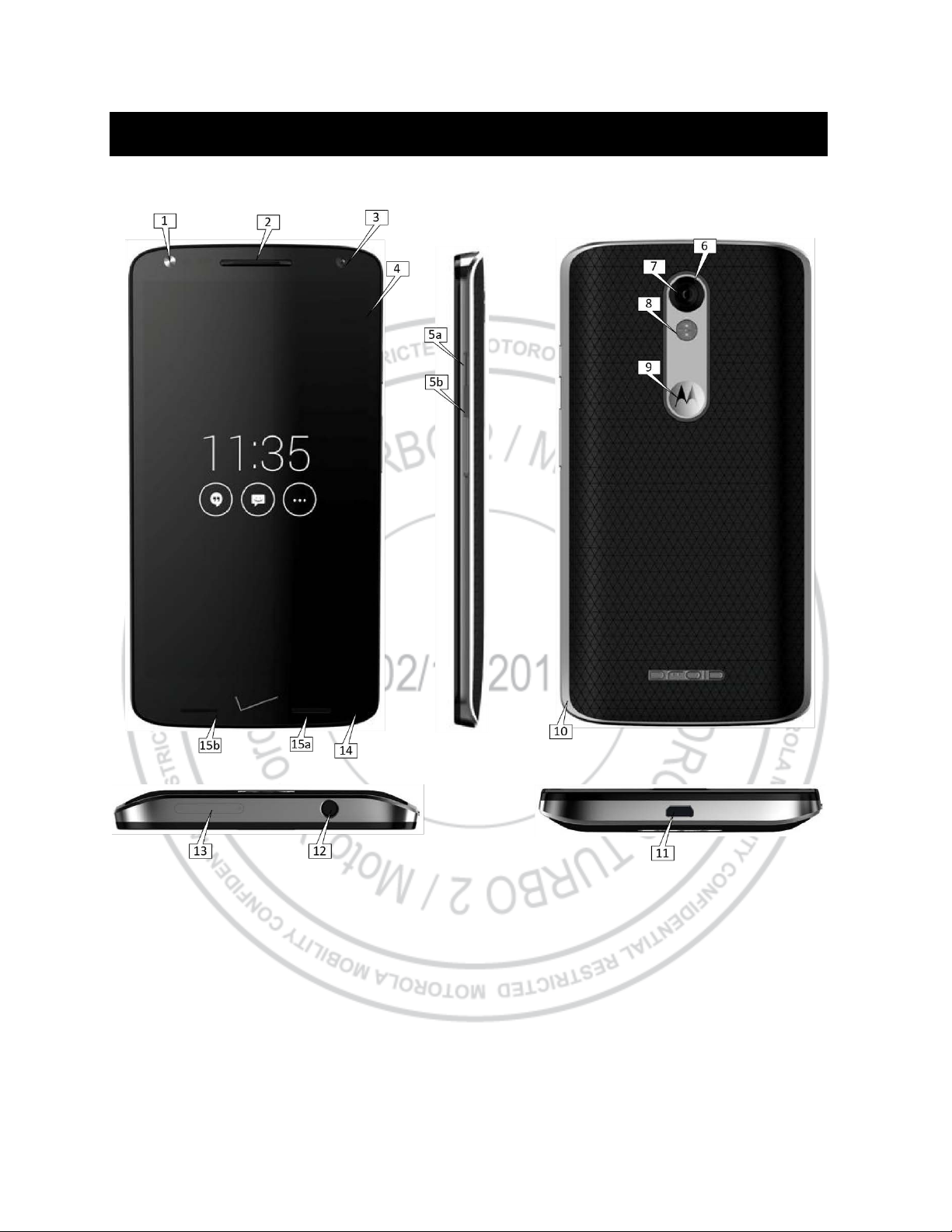
External Views
Figure 1. External Views
Motorola Mobility Confidential Restricted:
PAGE 8 Do not share without consent from Motorola
DROID TURBO 2 / Moto X Force
Reference #
Description
1
Front-Facing LED Flash
2
Earpiece Speaker
3
Front-Facing Imager
4
Display Lens
5a
Power Key
5b
Volume Key
6
Rear-Facing Imager Bezel
7
Rear-Facing Imager
8
LED Flash
9
Motorola Logo
10
Rear Housing
11
USB Port
12
Headset Jack
13
SIM and SD Card Tray
14
Main Microphone
15a
Loudspeaker
15b
Loudspeaker
Level 2 – Service and Repair Manual
Table 1. External Views Parts List
Motorola Mobility Confidential Restricted:
PAGE 9 Do not share without consent from Motorola
DROID TURBO 2 / Moto X Force
Level 2 – Service and Repair Manual
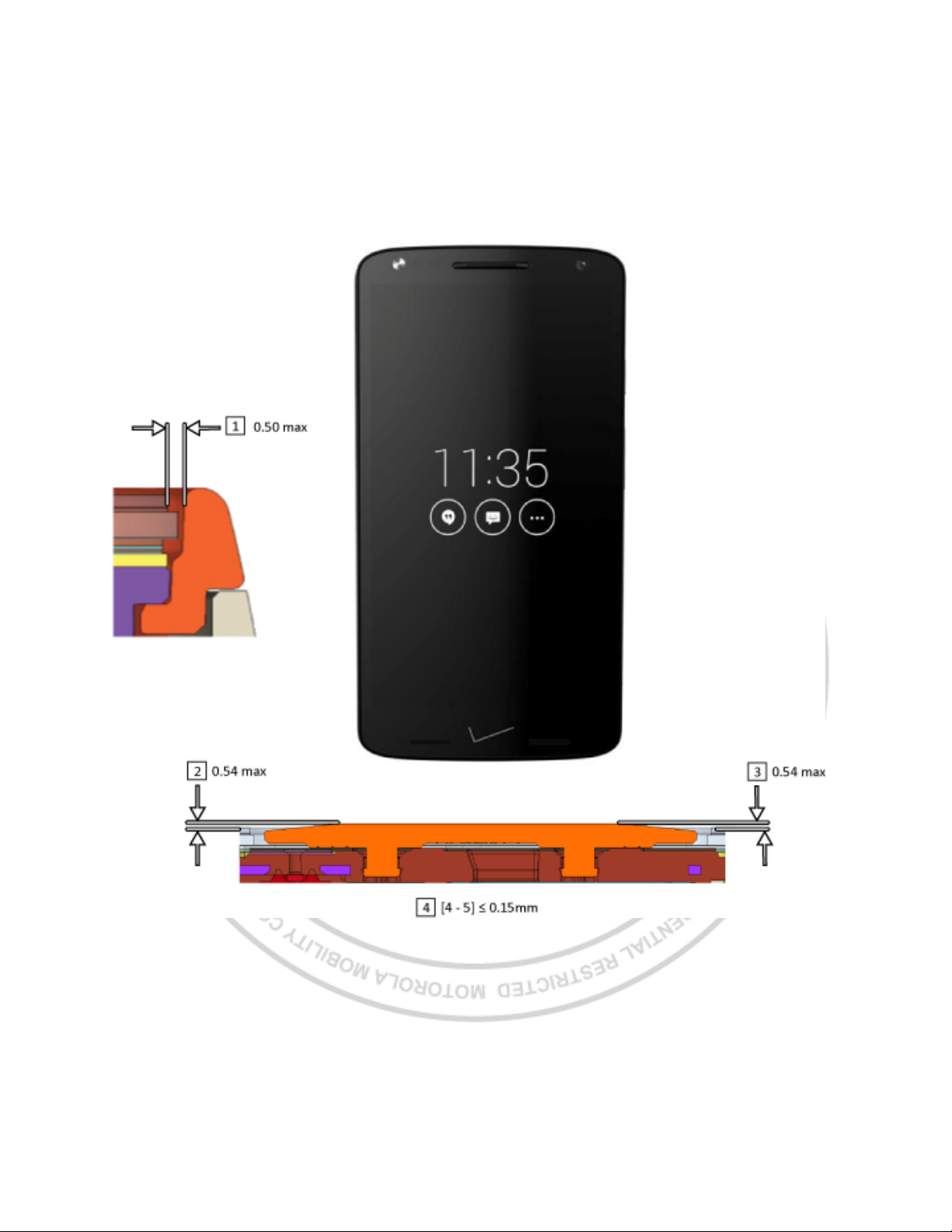
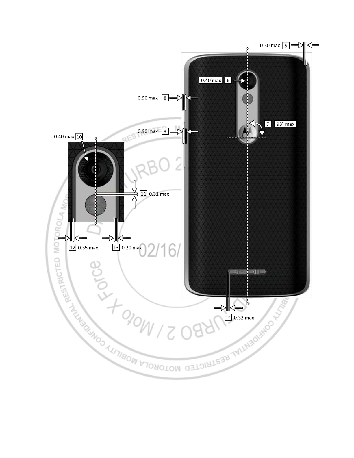
PSCD Gaps
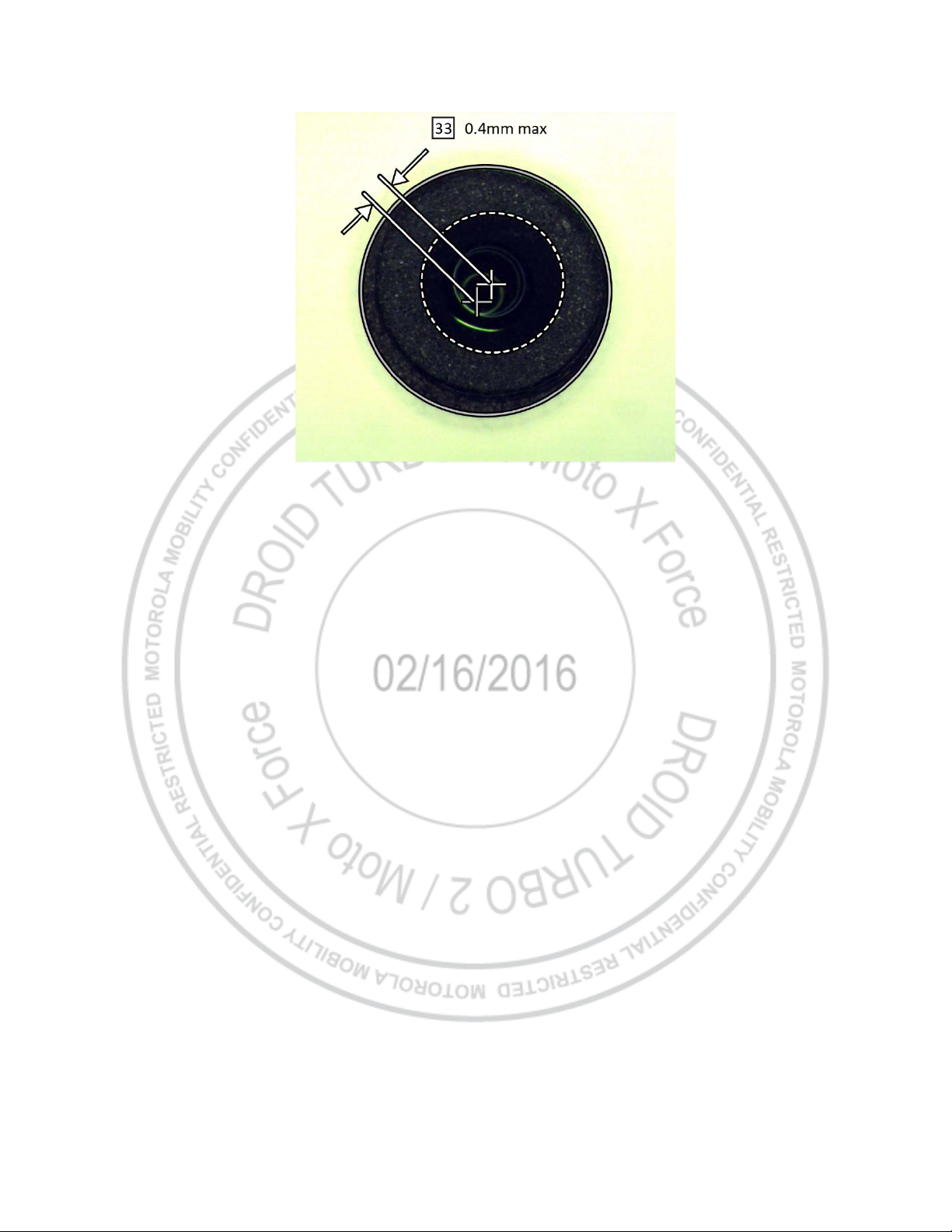
All dimensions are in millimeters (mm). The following gaps are considered maximum allowable without further approval
from a supervisor. Measure gaps at an angle perpendicular to the surface/area being measured. Feeler Gauges must
not be used at an angle as they will give false-positive results.
Figure 2. PSCD Front View
Motorola Mobility Confidential Restricted:
PAGE 10 Do not share without consent from Motorola
DROID TURBO 2 / Moto X Force
Level 2 – Service and Repair Manual
Figure 3. PSCD Rear View
Motorola Mobility Confidential Restricted:
PAGE 11 Do not share without consent from Motorola
DROID TURBO 2 / Moto X Force
Level 2 – Service and Repair Manual
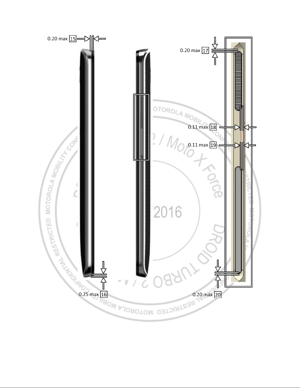
Figure 4. PSCD Side View
Motorola Mobility Confidential Restricted:
PAGE 12 Do not share without consent from Motorola
DROID TURBO 2 / Moto X Force
Level 2 – Service and Repair Manual
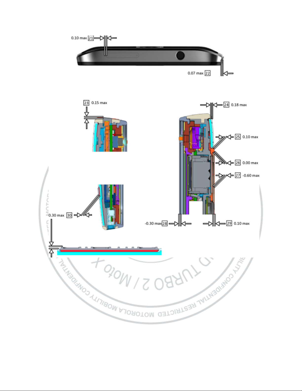
Figure 5. PSCD Top View and Cross Section View
Motorola Mobility Confidential Restricted:
PAGE 13 Do not share without consent from Motorola
DROID TURBO 2 / Moto X Force
Level 2 – Service and Repair Manual
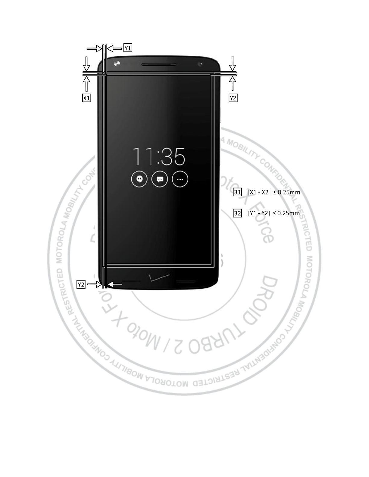
Figure 6. PSCD Display Alignment
Motorola Mobility Confidential Restricted:
PAGE 14 Do not share without consent from Motorola
DROID TURBO 2 / Moto X Force
Level 2 – Service and Repair Manual
Figure 7. PSCD Front-Facing Imager Alignment
Motorola Mobility Confidential Restricted:
PAGE 15 Do not share without consent from Motorola
DROID TURBO 2 / Moto X Force
Reference #
Description
1
Front Rim Housing to Lens Liner Perimeter
2
Lens Liner to Audio Deco (Left Point) Step
3
Lens Liner to Audio Deco (Right Point) Step
4
Audio Deco Tilt (Left Point vs. Right Point) Step
5
Rear Band Housing to Rear Inlay Perimeter
6
Main Imager Center to Main Imager Lens Artwork Concentricity
7
Camera Deco M Logo Rotation
8
Power Key to Rear Band Housing Step
9
Volume Key to Rear Band Housing Step
10
Main Imager Center to Camera Deco Concentricity
11
Camera Deco to Flash Lens Perimeter
12
Rear Inlay to Rear Bezel Perimeter
13
Rear Bezel to Camera Deco Perimeter
14
Rear Inlay to Droid Logo Perimeter
15
Front Rim Housing to Rear Band Housing (Z)
16
Front Rim Housing to Rear Band Housing Step (X & Y)
17
Rear Band Housing to Power Key (Y)
18
Rear Band Housing to Power Key (Z)
19
Rear Band Housing to Volume Key (Z)
20
Rear Band Housing to Volume Key (Y)
21
Rear Band Housing to SIM Door Perimeter
22
Front Rim Housing to Rear Band Housing Step (X & Y)
23
Rear Band Housing to SIM Door Step
24
Rear Band Housing to Rear Inlay Step
25
Rear Inlay to Rear Bezel Step
26
Rear Bezel to Camera Deco Step
27
Camera Deco to Camera Lens Step
28
Front Rim Housing to Main Lens Step
29
Camera Deco to Camera Flash Lens Step
30
Rear Inlay to Droid Logo Step
31
Main Lens View Area to Display Active Area (X1-X2)
32
Main Lens View Area to Display Active Area (Y1-Y2)
Level 2 – Service and Repair Manual
Table 2. PSCD Gap Measurements
Motorola Mobility Confidential Restricted:
PAGE 16 Do not share without consent from Motorola

DROID TURBO 2 / Moto X Force
Reference #
Description
33
Front-Facing Imager Center to Main Lens Artwork Center Concentricity
Level 2 – Service and Repair Manual
Motorola Mobility Confidential Restricted:
PAGE 17 Do not share without consent from Motorola

DROID TURBO 2 / Moto X Force
Reference #
Description
Recovery Part
1
DIE CUT,LINER,LENS,NO BRANDING
NO
ASSY,HSG,AU DECO,T&R,METALLIC RED,KINZIE (REWORK)
BZL,AU DECO,METALLIC DK GRY (ORIGINAL)
NO
ASSY,HSG,LENS W/FRONT HOUSING,PSA,BLACK,ROW,KINZIE
ASSY,HSG,LENS W/FRONT HOUSING,PSA,WHITE,ROW,KINZIE
YES
HSG,FRNT RIM,DECORATED,BLACK
HSG,FRNT RIM,DECORATED,WHITE
NO
5
GROM,SENSOR,KINZIE
NO
6
TRANSDUCER,OTHR,6X12X3,6X12X3MM RCVR F0=200HZ, AAC
NO
7
SEAL,O-RING,FRONT IMGR
NO
8
ASSY,FLXCKT,5MP IMAGER,KINZIE
YES
9
CABLE,COAX
YES
Level 2 – Service and Repair Manual
Exploded Views
Figure 8. Assembly Exploded View
Table 3. Exploded View Parts List
BZL,AU DECO,METALLIC BLK (REWORK)
BZL,AU DECO,METALLIC SLVR (REWORK)
2
3
4
BZL,AU DECO,METALLIC DK GRY (REWORK)
ASSY,HSG,AU DECO,T&R,METALLIC RED,KINZIE (ORIGINAL)
BZL,AU DECO,METALLIC BLK (ORIGINAL)
BZL,AU DECO,METALLIC SLVR (ORIGINAL)
Motorola Mobility Confidential Restricted:
PAGE 18 Do not share without consent from Motorola

DROID TURBO 2 / Moto X Force
Reference #
Description
Recovery Part
ASSY,HSG,SIM DOOR, FULL FLOOR TRAY,DARK MTLC GRAY, KINZIE
ASSY,HSG,SIM DOOR, FULL FLOOR TRAY,SINGLE SIM,RED,KINZIE
YES
ASSY,PWA,MN,BOUNCE VZW
ASSY,PWA,MN,32 GB,BOUNCE,CHINA,ROW
YES
12
ASSY,PWA,TOP,HSJ,VIBRATOR,KINZIE
YES
13
DIE CUT,ADHESIVE,PCB-CHASSIS
NO
14
ASSY,FLXCKT,IR LED,KINZIE
YES
15
PAD,CONDUCTIVE,FRONT IMGR
NO
16
ASSY,FLXCKT,CAMERA,REAR FACING 21MP IMAGER,KINZIE
YES
17
DIE CUT,ADHES,COP TAPE,PM8994
NO
18
ASSY,CHAS,REAR,KINZIE
YES
19
TRANSDUCER,POLYPHONIC,13X18X2P5
NO
20
ASSY,BAT,LI POLY,FB55,3760MAH,LG CHEM
YES
21
PAD,CONDUCTIVE,FRONT IMGR
NO
ASSY,HSG,REAR,METALLIC DK GRY
ASSY,HSG,REAR,RED,KINZIE
YES
23
ASSY,HSG,STOPPER,EARPIECE/FLASH,KINZIE
YES
24
SCR,MACH,M1.4
NO
25
ASSY,HSG,STOPPER,NFC CONN
YES
26
DIE CUT,ADHESIVE,INLAY,REAR COVER
NO
ASSY,HSG,INLAY,CSR,BLACK,REAR COVER,ROW
ASSY,HSG,INLAY,NYLON,GRAY,ROW,REAR CVR
YES
BZL,DECO,REAR,METALLIC DK GRY
BZL,DECO,REAR,METALLIC RED
YES
Level 2 – Service and Repair Manual
ASSY,HSG,SIM DOOR,FULL FLOOR TRAY,LIGHT
ASSY,HSG,SIM DOOR, FULL FLOOR TRAY,SINGLE SIM,METALLIC DK
GRAY
10
11
ASSY,HSG,SIM DOOR, FULL FLOOR TRAY,SINGLE SIM,METALLIC
SILVER,KI
ASSY,HSG,SIM DOOR, FULL FLOOR TRAY,SINGLE SIM,METALLIC
CHAMPAGNE
ASSY,PWA,MN,BOUNCE,ROW
ASSY,PWA,MN,64 GB,BOUNCE,VZW
ASSY,PWA,MN,64 GB,BOUNCE,ROW
22
27
28
Motorola Mobility Confidential Restricted:
PAGE 19 Do not share without consent from Motorola
ASSY,HSG,REAR,TIN SILVER,KINZIE
ASSY,HSG,REAR,CHAMPAGNE,KINZIE
ASSY,HSG,INLAY,CSR,WINTER WHITE,REAR COV
ASSY,HSG,INLAY,NYLON,BLACK,REAR CVR
ASSY,HSG,INLAY,NYLON,BLACK,ROW,REAR CVR
BZL,DECO,REAR,METALLIC SLVR
DROID TURBO 2 / Moto X Force
Reference #
Description
Recovery Part
29
DIE CUT,ADHES,CAMERA,DECO
NO
ASSY,CAMR DECO,METALLIC SLVR
ASSY,CAMR DECO,BLACK
YES
ASSY,DROID LOGO,DARK MTLC GRAY,KINZIE
ASSY,DROID LOGO,DARK GRAY/BLACK,KINZIE
NO
Level 2 – Service and Repair Manual
30
31
ASSY,CAMR DECO,METALLIC DK GRY
ASSY,CAMR DECO,METALLIC CHMPGN
ASSY,DROID LOGO,DARK MTLC SILVER,KINZIE
ASSY,DROID LOGO,METALLIC CHAMPAGNE,TALL,KINZIE
Motorola Mobility Confidential Restricted:
PAGE 20 Do not share without consent from Motorola
DROID TURBO 2 / Moto X Force
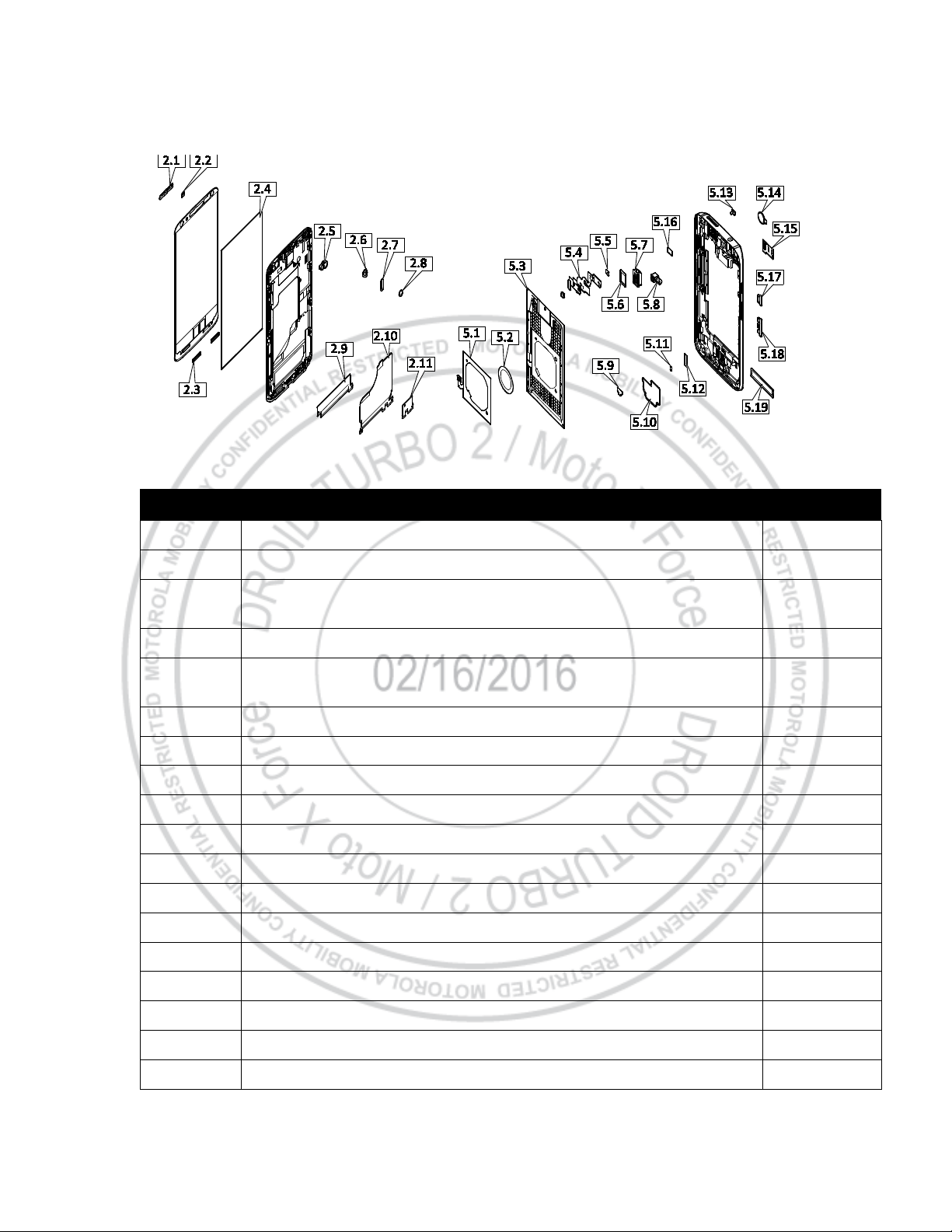
Reference #
Description
Recovery Part
2.1
SCRN,MESH,EARPIECE,TOP
NO
2.2
SCRN,MESH,MIC5
NO
SCRN,MESH,METAL,BOTTOM,BLACK,KINZIE
SCRN,MESH,METAL,BOTTOM,SILVER,KINZIE
NO
2.4
PAD,HT SPREADER,DISPLAY TO CHAS
NO
ASSY,HSG,FRNT FLSH LENS,KINZIE
ASSY,HSG,FRNT FLSH LENS,WHITE,KINZIE
NO
2.6
GROM,SEAL,MIC 5
NO
2.7
PAD,CONNECTOR,REAR IMGR
NO
2.8
PAD,CUSHION,COAX CBL
N
2.9
DIE CUT,KAPTON TAPE,FRONT CHASSIS,3.2MM X 22.5MM
NO
2.10
DIE CUT,ADHES,CONDUCTIVE,DISPLAY FLX
NO
2.11
SCRN,MESH,MIC 1&4
NO
5.1
FLX,NFC,WLC
NO
5.2
SPCR,WLC COIL
NO
5.3
ASSY,HSG,REAR,ENDO,KINZIE
YES
5.4
ASSY,FLXCKT,AU
NO
5.5
SCRN,MESH,MIC 2,CORE
NO
5.6
SEAL,HSET JCK
NO
5.7
CONN,JACK,HEADSET,3.5 MM DIA
YES
Level 2 – Service and Repair Manual
Figure 9. Subassembly Exploded View
Table 4. Subassembly Exploded View Parts List
2.3
2.5
Motorola Mobility Confidential Restricted:
PAGE 21 Do not share without consent from Motorola
DROID TURBO 2 / Moto X Force
Reference #
Description
Recovery Part
ALERT DEVICE,VIBR,MOTOR, ROTARY, 11.75 MM X X 4.55 MM MOTOR
BODY
YES
5.9
USB PAD
NO
5.10
DIE CUT,ADHES,LOUD
NO
5.11
PLT,METAL,ANTENNA,FEED,X+1
NO
5.12
SCRN,MESH,MIC3
NO
5.13
SCRN,MESH,MYLAR,MIC2,CAV
NO
5.14
LENS,IMAGER,REAR
NO
5.15
ASSY,FLXCKT,FLASH,BOUNCE
NO
5.16
PAD,CONNECTOR, FRNT IMGR
NO
5.17
BTN,POWER,GRAPHITE GRAY,KINZIE
YES
5.18
BTN,VOLUME,GRAPHITE GRAY,KINZIE
YES
5.19
SEAL,32014943 MYLAR, BV-REV_A
NO
Level 2 – Service and Repair Manual
5.8
Motorola Mobility Confidential Restricted:
PAGE 22 Do not share without consent from Motorola
DROID TURBO 2 / Moto X Force
Description
Part #
Picture / Drawing
Level 2 – Service and Repair Manual
DLN LINER REPLACEMENT
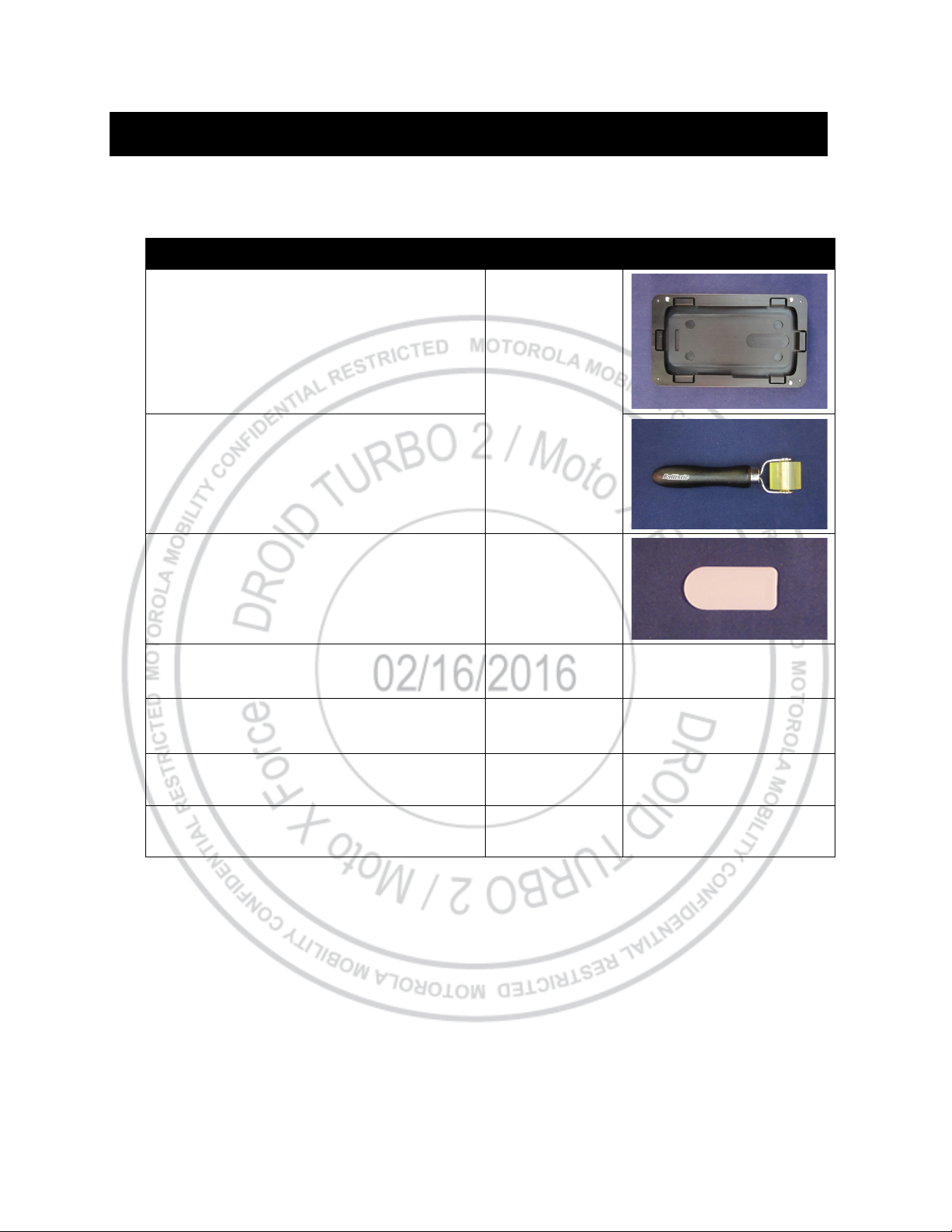
Tools Required for DLN Liner Replacement
The following tools are required to replace the DLN Liner on the DROID TURBO 2 / Moto X Force phone.
Bounce Lens Liner Alignment Fixture
3-00-E3-10000
Lens Liner Roller
Lens Removal Pick Tool 3-00-E4-10000
Kimwipes
Alpha Dry Wipes
Compressed Air Spray Can -- --
Gloves or Finger Collets -- --
01018766001W
01018765001W
--
--
Motorola Mobility Confidential Restricted:
PAGE 23 Do not share without consent from Motorola
DROID TURBO 2 / Moto X Force
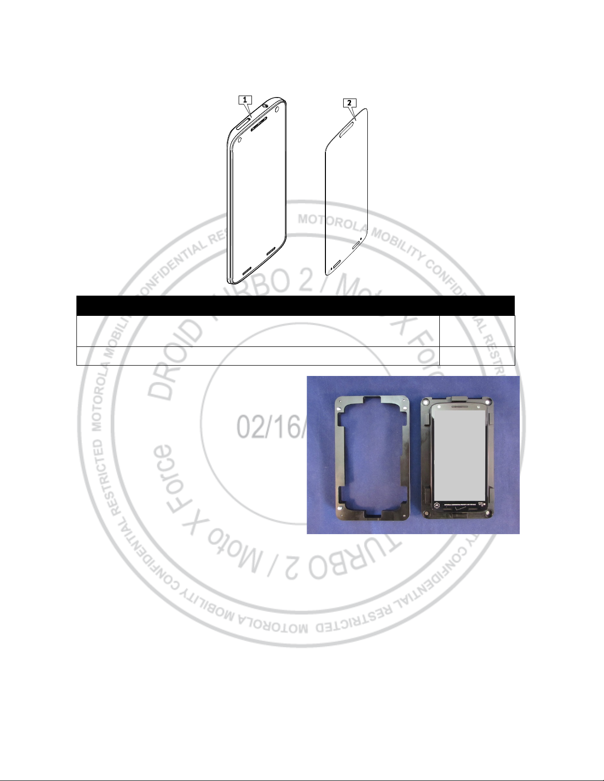
Description
Reference #
ASSY,HSG,LENS W/ FRNT HOUSING,PSA,BLACK,KINZIE
ASSY,HSG,LENS W/ FRNT HOUSING,PSA,WHITE,KINZIE
1
DIE CUT,LINER,LENS,NO BRANDING
2
Level 2 – Service and Repair Manual
MASC Procedure
1. Place the phone in the Bounce Lens Liner
Alignment Fixture (3-00-E3-10000).
Motorola Mobility Confidential Restricted:
PAGE 24 Do not share without consent from Motorola
DROID TURBO 2 / Moto X Force
Level 2 – Service and Repair Manual
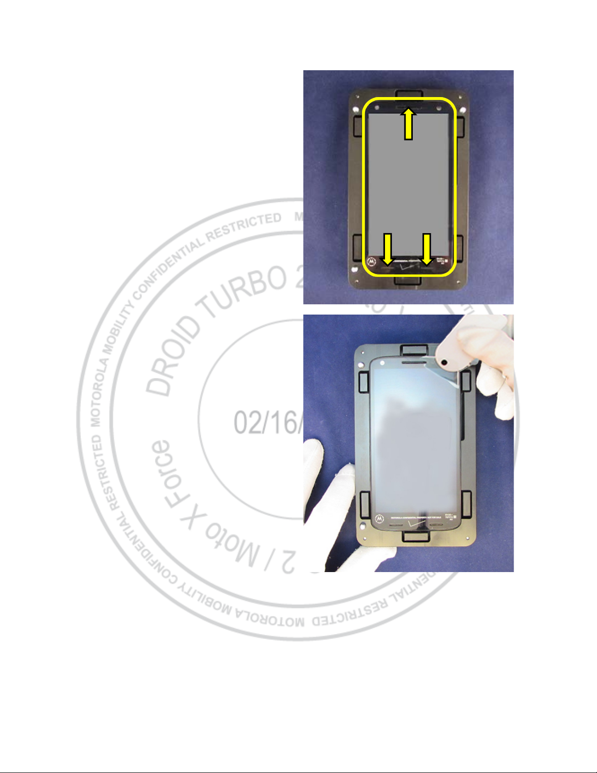
2. Place the alignment lid on the fixture.
3. Spray the Display and all 3 audio ports with
compressed air to remove any dust or foreign
material.
4. Use the Lens Removal Pick Tool (3-00-E4-
10000) to lift the corner of the old DLN Liner, and
then peel it off the Display.
Motorola Mobility Confidential Restricted:
PAGE 25 Do not share without consent from Motorola
DROID TURBO 2 / Moto X Force
Level 2 – Service and Repair Manual
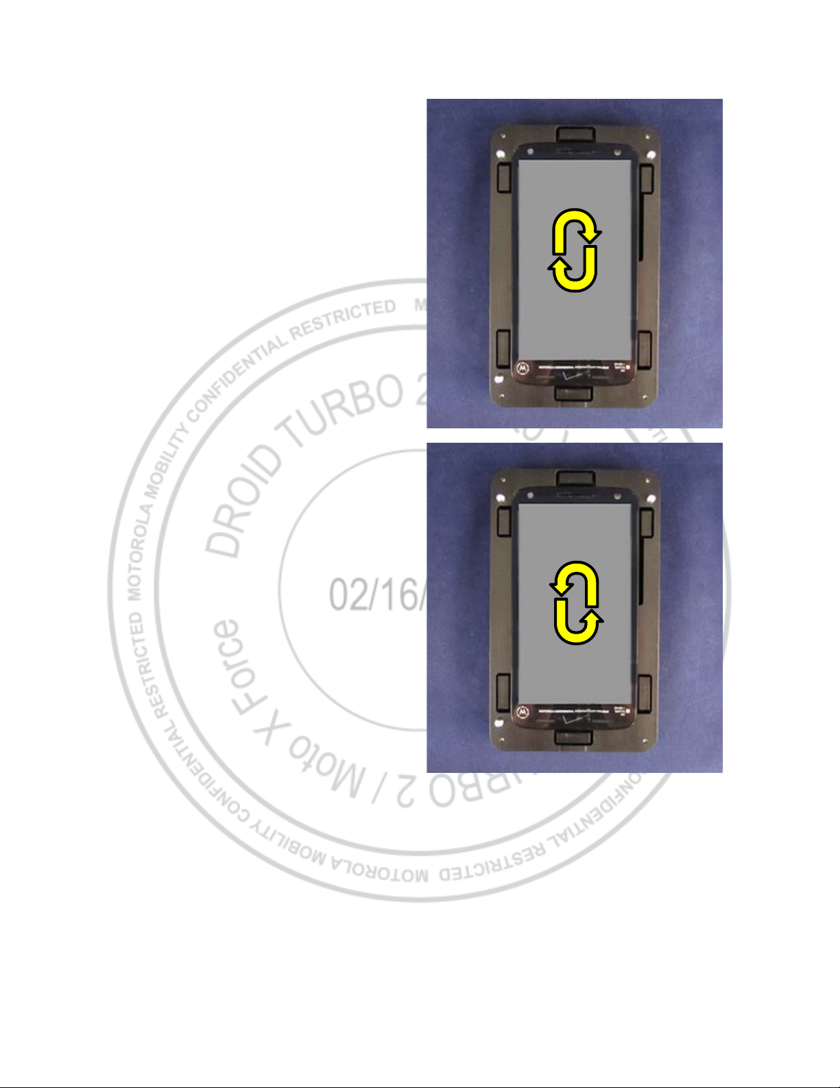
5. Wipe the Display with a Kimwipe in a clockwise
motion and remove any lint or dust.
6. Wipe the Display with an Alpha Dry Wipe in a
counterclockwise motion.
7. Spray the Display with compressed air to remove
any dust or foreign material.
8. Verify the Display is free of lint, dust, or any other
foreign material.
Motorola Mobility Confidential Restricted:
PAGE 26 Do not share without consent from Motorola
DROID TURBO 2 / Moto X Force
Level 2 – Service and Repair Manual
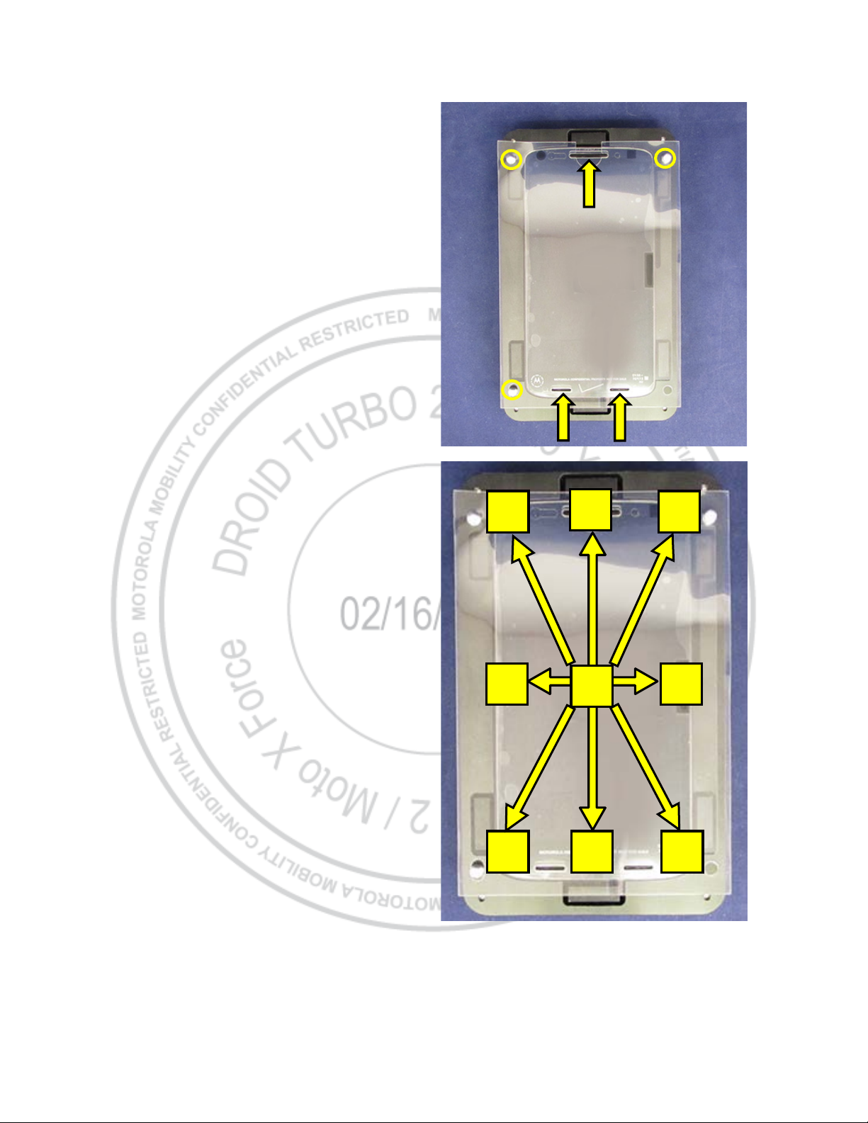
9. Remove the adhesive liner from the DLN Liner.
10. Place the DLN Liner into the fixture over the
Display, using the pins in the fixture and the 3
audio ports and the 3 pins to align it.
11. Use the Lens Liner Roller or Lens Removal Pick
Tool to apply manual pressure to the DLN Liner
as follows:
• Place the roller or pick on point 1 and slide
out to point 2.
• Place the roller or pick on point 1 and slide
out to point 3.
• Place the roller or pick on point 1 and slide
out to point 4.
• Place the roller or pick on point 1 and slide
out to point 5.
5
3
4 4
2
1
5
2
3
Motorola Mobility Confidential Restricted:
PAGE 27 Do not share without consent from Motorola
DROID TURBO 2 / Moto X Force
Level 2 – Service and Repair Manual
12. Remove the top liner from the DLN Liner.
13. Remove the phone from the fixture.
14. Use the roller or pick to press out any remaining
air bubbles.
NOTE
Small air bubbles will disappear over the next 48
hours.
Motorola Mobility Confidential Restricted:
PAGE 28 Do not share without consent from Motorola

DROID TURBO 2 / Moto X Force
Level 2 – Service and Repair Manual
Customer Procedure
1. Power off the phone.
2. Use the Lens Removal Pick Tool to lift the
corner. Then, peel off the lens.
3. Use the wet cloth, then dry cloth. Make sure
there’s no lint or dust left.
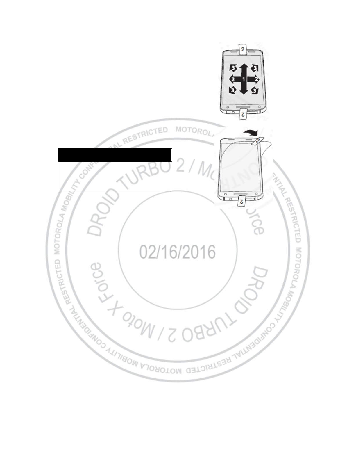
4. Pull tab 1 to remove the back cling.
5. Carefully align the new lens using the audio ports
as guides.
Motorola Mobility Confidential Restricted:
PAGE 29 Do not share without consent from Motorola
DROID TURBO 2 / Moto X Force
Level 2 – Service and Repair Manual
6. Press and drag down, then across the center.
Wait 15 seconds, then press outward from the
center.
7. Pull tab 2 to remove the top cling. Wait 24 hours
and press out any remaining air bubbles.
NOTE
Use the tool to gently press down any air pockets.
Small air bubbles may disappear over the next 48
hours.
Motorola Mobility Confidential Restricted:
PAGE 30 Do not share without consent from Motorola
 Loading...