

Page 1
MINITOR V
SELECTIVE CALL
ALERT MONITOR RECEIVER
USERS’ GUIDE
Page 2

Intrinsically Safe Radio Information
Anyone intending to use a radio in a location where hazardous
concentrations of flammable materials exist (hazardous atmosphere)
is advised to become familiar with the subject of intrinsic safety and
with the National Electric Code NFPA 70 (National Fire Protection
Association) Article 500 (hazardous [classified] locations). UL
Approval labels are attached to the Minitor V pager to identify the unit
as being UL Approved for specified hazardous atmospheres. This
label specifies the hazardous Class/Division/Group which will appear
as follows:
RAD DEV FOR HAZ LOC INT SAFE
DIV 1, I, CD; II, EFG Temp code T3C
RAD DEV FOR HAZ LOC INT SAFE
EXIA: DIV 1, I, CD; II, EFG-T3C
Substitution of Components may impair intrinsic safety.
The following is the Approved battery listing to be used for the UL
Approved Minitor V.
• Do not operate equipment in a hazardous atmosphere unless it is a
type especially qualified (for example, UL Approved) for such use. An
explosion or fire may result.
• Do not operate a UL Approved Product in a hazardous atmosphere
if it has been physically damaged (for example, cracked housing). An
explosion or fire may result.
• Do not replace or charge batteries in a hazardous atmosphere.
Contact sparking may occur while installing or removing batteries and
cause an explosion or fire.
• Do not replace or change accessories in a hazardous atmosphere.
Contact sparking may occur while installing or removing accessories
and cause an explosion or fire.
1
Page 3

• Turn a radio off before removing or installing a battery or
accessory.
• Do not disassemble a UL Approved Product unit in any way that
exposes the internal electrical circuits of the unit.
• Do not substitute components. This could v
rating.
oid the intrinsic safety
2
Page 4

INTRODUCTION
Congratulations on
V Alert Monitor. Motorola’s advanced technology offers
unique features and benefits that set the industry standards
for performance, reliability, and styling. The compact alert
monitor is offered in a variety of models including:
• One-Frequency Standard with VIBRA-Page™
• One-Frequency Standard Stored Voice and VIBRA-Page™
• Two-Frequency with Scan and VIBRA-Page™
• Two-Frequency Store Voice with Scan and VIBRA-Page™
Other user programmable options are available to provide a
wide selection of features and special applications.
INSPECTION
Verif
the back of the alert monitor. Inspect the equipment
thoroughly. If any part of the equipment has been damaged
in transit, report the extent of the damage to the
transportation company immediately.
y the model number information located on the label on
your purchase of the Motorola MINITOR
BATTERY TYPES
The alert monitor is powered by one rechargeable Ni-MH
battery pack.
3
Page 5
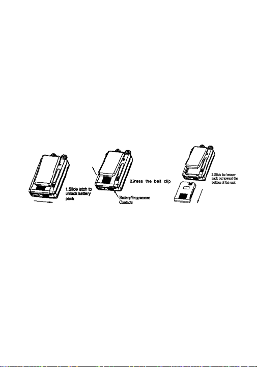
BATTERY INSTALLATION
: For optimum performance, the Ni-MH battery pack
NOTE
must be fully charged before operating your alert monitor.
Install your batteries as follows:
1. Release the battery lock, and slide the battery pack latch
towards the right to unlock the battery pack.
2. Press the clip.
3. Slide out on the battery pack as shown below.
4. Slide in the battery pack into place, and then slide the
battery pack latch to the locked position.
CAUTION: If th
monitor will not function and the batteries will not charge.
e batteries are improperly installed, the alert
4
Page 6
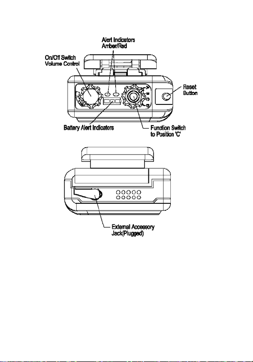
STANDARD FEATURES AND CONTROLS (All Models)
ON/OFF Switch/Volume Control
The ON
single control located on the top of the alert monitor as
shown above. Turning the control knob a few degrees in a
clockwise direction applies power to the receiver, and an
audible beep is sounded to indicate that the alert monitor is
turned on. As the control is rotated in a clockwise direction,
the volume level of any received
/OFF SWITCH/VOLUME CONTROL is a combined
5
Page 7

message and alert tone is increased. Rotating the control in
the opposite (counterclockwise) direction reduces the audio
level, and turns the alert monitor off.
Audible/Visual Alert Indicators
When your alert
and amber LEDs on the control panel light and an alert tone
is sounded until the decoder circuit power-up is complete.
Thereafter, whenever a properly encoded message is
received, the red LED flashes and an audio alert is sounded.
If the battery voltage falls below the level required for reliable
operation, a low battery pulse tones sounds and the red LED
flashes. Following any subsequent audio message, the
momentary low battery pulse tone is repeated until the
battery pack is recharged or replaced. If the function switch
is set to a vibrate position, just the red LED flashes to
indicate a low battery state.
Function Switch
According to the
will be configured to 4 positions. Different function modes
(monitor/selective call, scan, etc.) can be configured for any
position of the switch.
Channel Monitoring
monitor is initially turned on, both the red
specific model ordered, the function switch
When the function switch is set to a monitor position,
all voice communications on the selected chan nel is
heard through the speaker. When monitoring channel 1 or
2 all ordered alert options are functional.
Reset Button
After receipt of a properl
completion of that message, the alert monitor will
automatically reset to the programmed operational mode
y coded message and after
6
Page 8

(see Field Installed Options section for reset options).
Some of these reset functions will place the pager in the
monitor more. In these cases, or when the manual reset
function is programmed into the pager, press the reset
button to return your alert monitor to the standby mode.
External Speaker Jack
When the alert monitor is used in
or when privacy is needed, an optional Motorola approved
lapel speaker or earpiece can be connected to the
external accessory jack located on the top control panel.
The jack is fitted with a protective plug.
NOTE: To prevent entry of dust and moisture, the plug
should be inserted whenever the external accessory jack
is not being used.
Belt Clip Feature
An integral part of the clip on the
security hook. This hook is intended to allow easy removal
of the alert monitor, while at the same time preventing the
unit from being pulled off your belt.
Scan (Two-Frequency Models Only)
All alert monitors that are equipped with two frequencies
are capable of scanning the two channels for selective call
or monitoring purposes.
STORED VOICE MODEL FEATURES AND CONTROLS
The alert
store up to 8 minutes of voice messages. Messages are
stored according to their length. If preferred, the alert
monitor can be programmed for stored voice fixed message
lengths of 30, 60 or 120 seconds. Messages can be deleted
monitors that include the stored voice feature can
high-noise environments
back of your monitor is a
7
Page 9

by either incoming new messages replacing older messages
or by turning the receiver off.
Unread Message Indicator
The red LED turns on if there are any unread messages.
Reminder Alert
The pager generates a reminder alert approximately every
two minutes when an unread message exists.
Voice Memo
When the alert
switch is moved to a new position, a voice prompt will be
played to announce the mode that the pager is in. This
feature is available with the stored voice pagers only and
can be disabled through the programming software.
FIELD INSTALLED OPTIONS
monitor is powered on or the function select
Fixed-Alert, Audio-Only Volume Control
When this option is installed, the alert tone is factory
preset (non-adjustable) at the maximum volume level.
Turning the volume control varies only the voice message
volume level.
NOTE: Use of audio accessories is not recommended
with this option.
Time-Out Auto Reset
This feature allows the alert monitor to be automatically
reset after a predetermined amount of time. This places
the alert monitor back in standby mode to help conserve
battery power.
8
Page 10

Several alert monitor field programmable options are
available to include the following:
• Priority Scan
• Non Priority Scan
• Silent Scan
• Alert Duration
• Priority Alert
• On/Off Duty
• Reset Options
- Carrier Reset
- Delayed N Carrier Reset
- Manual Reset
- Revert Reset
- Time Out Reset
- Delayed N Revert Reset
• Stored Voice Options
- Max Message Lengths
- Call Reminder
• Push-To-Listen
Contact a Motorola authorized paging system dealer or
call 1-800-548-9954 for the addition of these features.
9
Page 11

OPERATION
Perform the following steps to condition your alert monitor
for operation:
1. Set the FUNCTION switch to a tone-alert position.
2. Rotate the ON-OFF SWITCH/VOLUME CONTROL
clockwise to turn on the alert monitor. Eight short beep
sounds occur and both LEDs light, indicating that power is
applied.
3. Set the FUNCTION switch to a monitor position.
4. Listen for a transmission and adjust the volume control
to a comfortable listening level.
5. If no transmission is heard, hold down the RESET
button and adjust the background noise to a comfortable
listening level. It may be necessary to readjust the volume
when a voice signal is present.
6. Set the FUNCTION switch to the desired operating
mode, i.e., selective call tone, selective call vibrate,
monitor, scan, etc.
7. Turn off the monitor by rotating the ON-OFF
SWITCH/VOLUME CONTROL counterclockwise until a
click is heard and the mechanical stop is reached.
SCAN OPERATION
Priority Scan
If the alert monitor is programmed for priority scan, the
frequency programmed as F1 is designated as the priority
channel. If there is no traffic on F1, the alert monitor
alternately listens to F1 and F2 until a transmission is
detected. If a transmission is detected on F1, the alert
monitor stays on that channel until the transmission
ceases. The alert monitor only decodes tones on the F1
channel. No tones are decoded on the F2 channel.
10
Page 12

If the alert monitor detects a transmission on F2 it stops
on F2 then listens for transmissions on F1. Scan back
time is programmable and can be set to 0.5, 1, or 2second increments. If a transmission is detected on F1,
the alert monitor switches to F1 cutting off any
transmission on F2. When switching from F2 to F1, the
alert monitor listens for any tones and alerts if the proper
tones are detected. It should be noted that the detection
of tones is very dependent on the duration of the tone
sent over the air. To ensure reliable alerting, it is
recommended that this feature only be used when the first
tone duration transmitted is one second or more.
Non-priority Scan
In the non-priority scan mode, the alert monitor alternately
listens on F1 and F2 for any transmission. A transmission
on either channel causes the alert monitor to stop on that
channel until the signal disappears. In non-priority scan,
the alert monitor decodes tones on either F1 or F2
provided the alert monitor has listened to the appropriate
channel at the correct time. However, it should be noted
that if the alert monitor is listening to traffic on F2 and an
alert is transmitted on F1, the alert monitor will not hear
that signal until the transmission on F2 is finished.
Therefore, an emergency alert could be missed if the alert
monitor is listening to traffic on one channel with tones
being sent out on the other channel.
Silent Scan
In the silent scan mode, the alert monitor alternately
listens on F1 and F2 for alert tones. Detection of alert
tones on each channel causes the alert monitor to stop on
that channel until the signal disappears. In the silent scan
11
Page 13

more, the alert monitor decodes tones on either F1 or F2
provided the alert monitor has listened to the appropriate
channel at the correct time. However, it should be noted
that if the alert monitor is listening to traffic on F2 and an
alert is transmitted on F1, the alert monitor will not hear
that signal until the transmission on F2 is finished.
Therefore, an emergency alert could be missed if the alert
monitor is listening to traffic on one channel with tones
being sent out on the other channel. Scan back time is
set to 0.25 seconds. To ensure reliable alerting, it is
recommended that this feature only be used when the first
tone duration transmitted is one second or more.
STORED VOICE OPERATION
Selecti
ve Call Position:
In this position, the message is simultaneously stored as
you receive the voice communication. The message
recording cycle is complete under any of the following
conditions:
• When the maximum message length is complete
• When the squelch circuit no longer detects carrier signal
• When the delayed “N” cycle is complete
• When the timed-out reset cycle is complete
If channel traffic occurs after the page and message, and
before carrier signal is lost, that will also be stored in
memory. After storage is complete and carriers drops, the
alert monitor responds according to the programmed reset
mode. The alert monitor can be reset by pressing the
RESET button at any time.
12
Page 14

Scan/Monitor Positions
In these positions, the message is stored only when a
properly encoded message is received. Other
communications monitored on the channel that do not
alert your monitor are not stored.
Selective Playback of Message(s)
To playback a particular message in memory, press the
PLAYBACK button. Pressing once replays the newest
message in memory. Twice replays the second most
recent message and
back during message recording.
so on. Mess ages cannot be played
You may also playback older messages by pressing the
PLAYBACK button as you are listening to a message. If
you are listening to the most recent message, and want to
listen to an older message, press the PLAYBACK button
while listening to the current message. The playback
switches to an older message if it is still in storage.
If there are no messages in memory, a “memory empty”
tone is heard while the PLAYBACK button is pressed.
NOTE: A message is considered read if playback has
been initiated for more than 30 seconds or the end of the
message is reached, whichever occurs first.
BATTERY LIFE
Battery life depends upon the number of calls received
and length of each call, capacity and charge of the
battery, and the mode of operation. A battery gauge,
located between the knobs on top of the pager can be
13
Page 15

used to determine remaining battery capacity. To enable
the battery gauge, press the reset button. This will
illuminate the LED in the battery gauge. Three LED are
present and represent approximately one-third of the
battery capacity.
CLEANING YOUR PAGER
To clean smudges and grime from the exterior of your
pager, use a soft, non-abrasive cloth moistened in a mild
soap and water solution. Use a second cloth moistened
in clean water to wipe the surface clean. Do not immerse
in water. Do not use alcohol or other cleaning solutions.
REPAIR AND MAINTENANCE
Your alert monitor, properly handled, will provide quality
service for years. However, should it ever require service,
call 1-800-548-9954 for instructions.
ACCESSORIES
Motorola offers several accessories to increase
communications efficiently and provide many unique
benefits. Consult your Motorola sales representative for a
complete list of accessories, prices, and applications.
• Desktop Battery Charger
• Desktop Battery Charger Amplifier with Antenna
and Relay
• Earpieces
• Lapel Speaker
• Nylon Carrying Case
14
Page 16

Regulatory Agency Compliance
This device complies with part 15 of the FCC Rules.
Operation is subject to the following two conditions: (1)
This device may not cause harmful interference, and (2)
this device must accept any interference received,
including interference that may cause undesired
operation.
This equipment has been tested and found to comply with
the limits for a Class B digital device, pursuant to part 15
of the FCC Rules.
These limits are designed to provide reasonable
protection against harmful interference in a residential
installation. This equipment generates, uses and can
radiate radio frequency energy and, if not installed and
used in accordance with the instructions, may cause
harmful interference to radio communications.
However, there is no guarantee that interference will not
occur in a particular installation. If this equipment does
cause harmful interference to radio or television reception,
which can be determined by turning the equipment off and
on, the user is encouraged to try to correct the
interference by one or more of the following measures:
• Reorient or relocate the receiving antenna.
• Increase the separation between the equipment and
receiver
• Connect the equipment into an outlet on a circuit
different from that to which the receiver is connected.
• Consult the dealer or an experienced radio/TV
technician for help.
15
Page 17

Motorola, Minitor V, Minitor V logo, and VIBRA-Page
are trademarks or registered trademarks of Motorola,
Inc. Contents of this manual subject to change without
notice.
Reg. U.S. Pat. & Tm. Off.
© 2005 by Motorola, All Rights Reserved.
Global Enterprise and Mobility Solutions
1313 E. Algonquin Rd., Schaumburg, IL
60196-1081
Printed in U.S.A. 04/05
6880309R88
16
 Loading...