


MICOM
MOBAT USA
Tallahassee 32310 FL, USA
Owner’s Guide
Radio Control Application
Part number FVN4841
Option number G424
1720 West Paul Dirac Drive,
Cat. No. 6886869J01

Contents
Overview ............................................................................................................................. 1
The MICOM-3 Family ..................................................................................................1
PC Control and Programming Package .......................................................................1
MICOM Radio Control Application Features ................................................................2
RSS Panel ....................................................................................................2
RSS ALE Panel ............................................................................................. 3
Computer Interface Panel .............................................................................4
MICOM-3 Panel ............................................................................................5
How to … ......................................................................................................6
Installation .......................................................................................................................... 7
Contents of PC Control and Programming Package ....................................................7
Minimum Computer Requirements ..............................................................................7
Before you Start … ..................................................................................................... 7
Installation Procedure .................................................................................................8
Before starting the installation : ......................................................................8
To install the MICOM Radio Control application : ...........................................8
To test for proper installation :........................................................................8
Getting Started ...................................................................................................................9
Before You Begin Working ..........................................................................................9
Quick Start ..................................................................................................................9
Preliminary Steps ..........................................................................................9
Communication Port Configuration ................................................................9
General Procedures ....................................................................................................10
Menus and Commands ................................................................................. 10
MICOM Radio Control Application Windows .................................................12
The Menu Bars ..............................................................................................13
The Toolbars .................................................................................................14
The Status Line .............................................................................................15
Other Important Considerations ....................................................................15
RSS Panel ...........................................................................................................................16
RSS Panel Menus .......................................................................................................16
File Menu ......................................................................................................17
View/Change Menu .......................................................................................17
Service Menu ................................................................................................17
Preferences Menu .........................................................................................17
RSS Panel Toolbar Buttons ........................................................................... 18
Radio Configuration Summary Window .......................................................................19
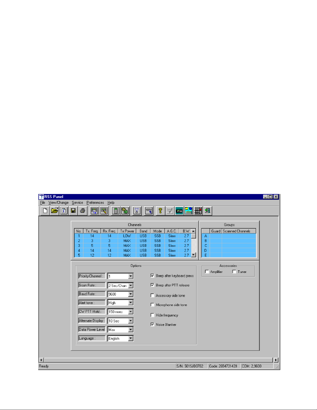
Channels Field ..............................................................................................20
i

Groups Field ..................................................................................................20
................................
P
references Menu
................................
................................
................................
44
................................
Channels Tab
................................
................................
................................
................................
46
Options Field ..................................................................................................21
Accessories Field ...........................................................................................22
Radio Wide Information Window ..................................................................................23
Configuration Check Window .......................................................................................24
Preferences Menu ........................................................................................................25
Communication Ports .....................................................................................25
Read Device ................................................................................................................26
Write Device ................................................................................................................26
Radio Configuration Settings ........................................................................................27
Channels Configuration ................................................................................................27
Groups .........................................................................................................................28
Built-in-Test Equipment ................................................................................................29
RSS ALE Panel ....................................................................................................................30
RSS ALE Panel Menus ................................................................................................30
File Menu .......................................................................................................30
View/Change Menu ........................................................................................31
Preferences Menu ..........................................................................................31
RSS ALE Panel Toolbar Buttons ....................................................................31
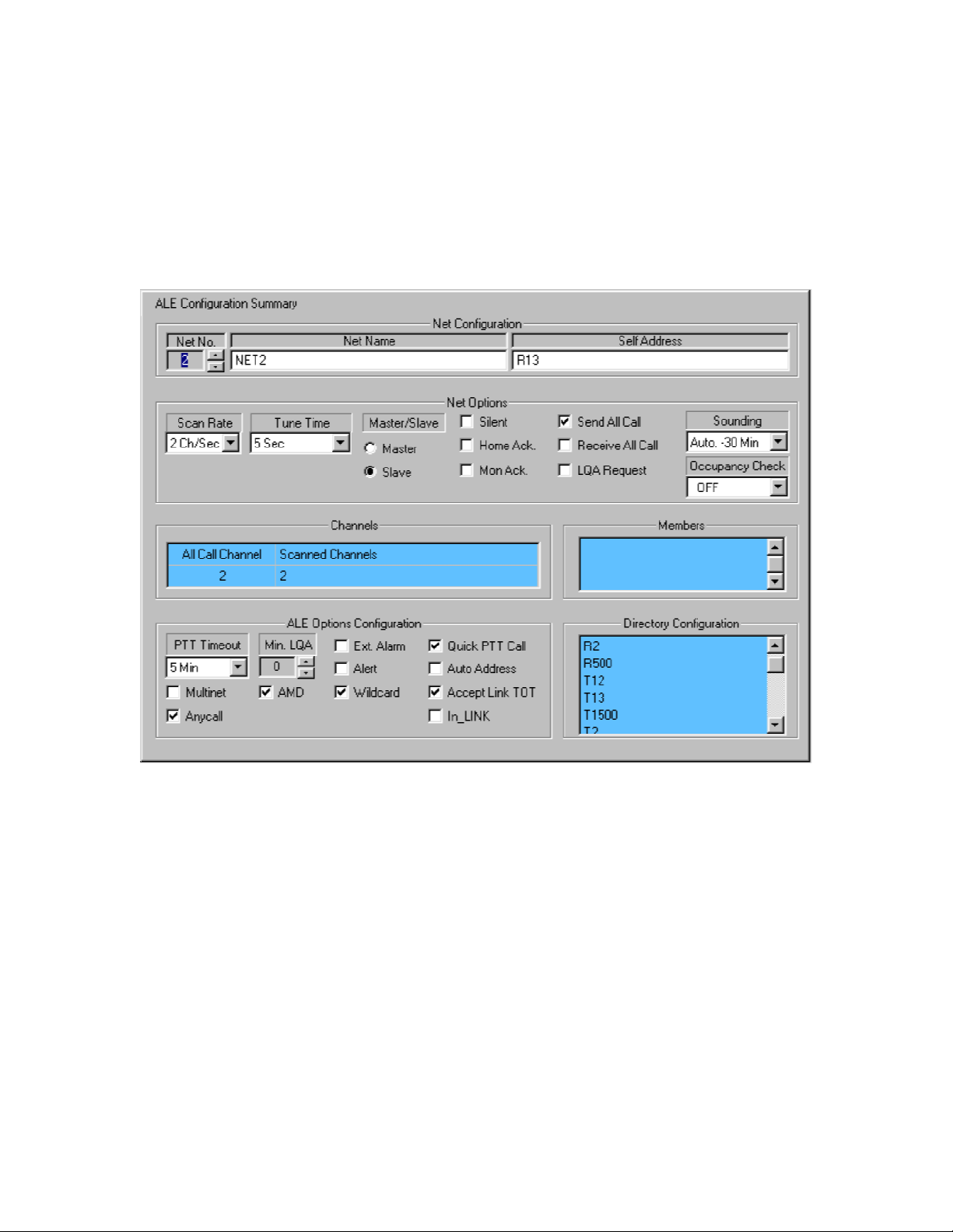
ALE Configuration Summary Window ..........................................................................33
Net Configuration Field ..................................................................................34
ALE Options Configuration Field ....................................................................35
Directory Configuration Field ..........................................................................35
ALE Configuration Submenu ........................................................................................36
ALE Directory Configuration ...........................................................................36
ALE Messages Configuration .......................................................................................37
Automatic Dial Configuration ........................................................................................38
Radio Wide Information Window ..................................................................................40
ALE Configuration Check Window ...............................................................................41
Computer Interface Panel ...................................................................................................43
Computer Interface Panel Menus .................................................................................43
File Menu .......................................................................................................43
View/Change Menu ........................................................................................44
ii
Commands Menu ................................................................
Computer Interface Panel Toolbar Buttons ................................
45
Clarifier ......................................................................................................... 46
Notch Filter .................................................................................................... 46
Channel Mode Controls ................................................................................ 47

ALE Controls .............................................................................................................. 49
Update Link Quality Controls ...................................................................................... 50
Using the Stack ........................................................................................................... 51
Viewing the Stack List ................................................................................... 51
The Stack List Toolbar .................................................................................. 52
Replying to Unanswered Calls ...................................................................... 52
To reply to an unanswered call registered in the Stack list: 52
Log File ....................................................................................................................... 53
Incoming Call Notification ........................................................................................... 53
MICOM Panel ...................................................................................................................... 54
MICOM Panel Menus .................................................................................................. 54
File Menu ...................................................................................................... 54
View/Change Menu ....................................................................................... 55
Preferences Menu ......................................................................................... 55
Toolbar Buttons ............................................................................................ 55
Using the MICOM Panel ............................................................................... 56
Log File ......................................................................................................... 56

iv

Overview
The MICOM
-
3 Family
Overview
MICOM-3F, MICOM-3T and MICOM-3R are part of a family of high-performance, DSP-based, multipurpose HF SSB radios intended for use in voice, data and fax communications, in both mobile and
base station configurations. MICOM-3 radios can be integrated into a wide range of advanced
communication systems, including data and fax networks, VHF-UHF-microwave and telephone
interconnect, high-power (500 W and 1 kW) systems, etc.
MICOM-3 support channel scanning, and the advanced Automatic Link Establishment (ALE)
feature. ALE provides unique advantages that significantly reduce operational inconveniences
caused by the very nature of HF channels. ALE enables the MICOM-3 to automatically test all
channels on the system and then use the best working channel available whenever you call a
specific station or group of stations operating in a network. Thus, ALE ensures the best link possible
and achieve greater efficiency and reliability in communications.
The ALE main features are:
x Automatic sounding, which provides channel quality testing.
x Multiple types of calls (station call,groupcall, All Call(emergency call) for calling all ALE
stations simultaneously, etc.) and support for multiple nets.
x Automatic Message Display (AMD), which enables automatic dispatch of preprogrammed
messages when establishing a link with another station or stations.
x Automatic Dial, which enables automatic dialing to a pre-programmed station, including the
automatic dispatch of a preprogrammed message.
When using ALE, MICOM-3 HF-SSB radios are interoperable with any other radios supporting
FED-STD-1045Aand MIL-STD-188-141B.
For more information on the characteristics and operation of MICOM-3 radios, refer to the MICOM-
3F/3T/3R Owner’s Guide (6886867J01).
PC Control and Programming Package
The PC Control and Programming package includes the MICOM Radio Control (MRC) application, a
simple, user-friendly program that can be run on any personal computer with Microsoft Windows®
95 and later versions. To control or configure a radio, you must connect it to a serial communication
port of the personal computer (the required cable is supplied in the package).
The MRC enables remote operation of MICOM-3 radios via a personal computer, and programming
of its features and operational parameters. Programming, or customizing, personalizes a radio for
the needs of individual customers, resulting in radios with unique personalities.
This manualis targetedfor anyone who wantsto programfeatures into the MICOM-3 radio,or use a
computer to control the radios.
6
MICOM-3 PC Control & Programming Owner’s Guide
Also allows displaying the installed features and options. This information, as well as the radio
e user
MICOM Radio Control Application Features
The MICOM Radio Control application providesan integrated control centerthat seamlessly
combines the following functions:
x Radio Service Software Panel (RSS Panel)
x Radio Service Software for ALE Panel (RSS ALE Panel) x
Computer Interface Panel
x MICOM Panel
RSS Panel
Used to program the features and operational parameters of the radio for operation in thefollowing
modes:
x Discrete channels
x Scan mode (a mode available when ALE is disabled).
configuration parameters, are retrieved from the radio upon connection (and whenever th
wants to).
RSS parameters are stored in files with the *.rss extension. The prepared parameters can be
downloaded (written) to the radio whenever necessary.
With the RSS Panel, you can perform extensive testing of the radio by means of its built-in test
equipment (BITE) function.
7
Overview
RSS ALE Panel
Used to program the additional features and operational parameters of the radio for operation in
the ALE mode.
You can also plan and configure ALE networks, define theirmembers, manage the ALE network
directories, and create and edit paging (AMD) messages.
The RSS ALE panel also allows displaying the installed features and options.
ALE parameters are stored in files with the *.ale extension. Other ALE information is stored in files
with *.txt extension.
8
MICOM-3 PC Control & Programming Owner’s Guide
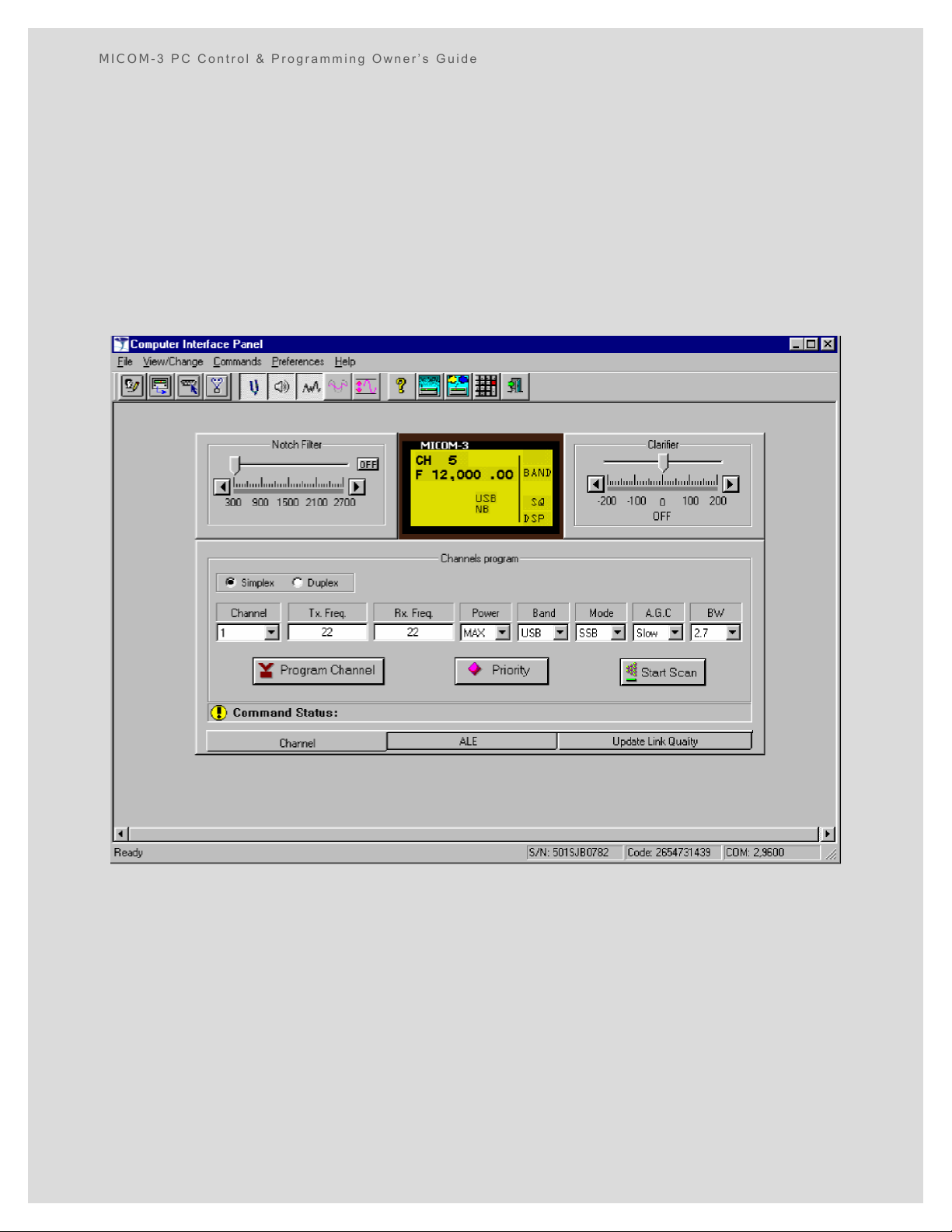
Computer Interface Panel
Used to control the MICOM-3 radio from a remote or local location, using a personal computer.
Separate panels are used to control the radio in the following main modes: x Channel mode
(shown below)
x ALE mode: for convenience, the panel used for regular operation has been separated from the
panel used to initiate link quality updates.
Storesinformationon calls sent and received in a log file. The file can be saved, edited and
printed as necessary.
The Computer Interface Panel also enables performing extensive testing by means of the radio
BITE function.
Overview
3 panel that can be directly controlled by means of the computer
most widely used panel
just as you would operate the radio
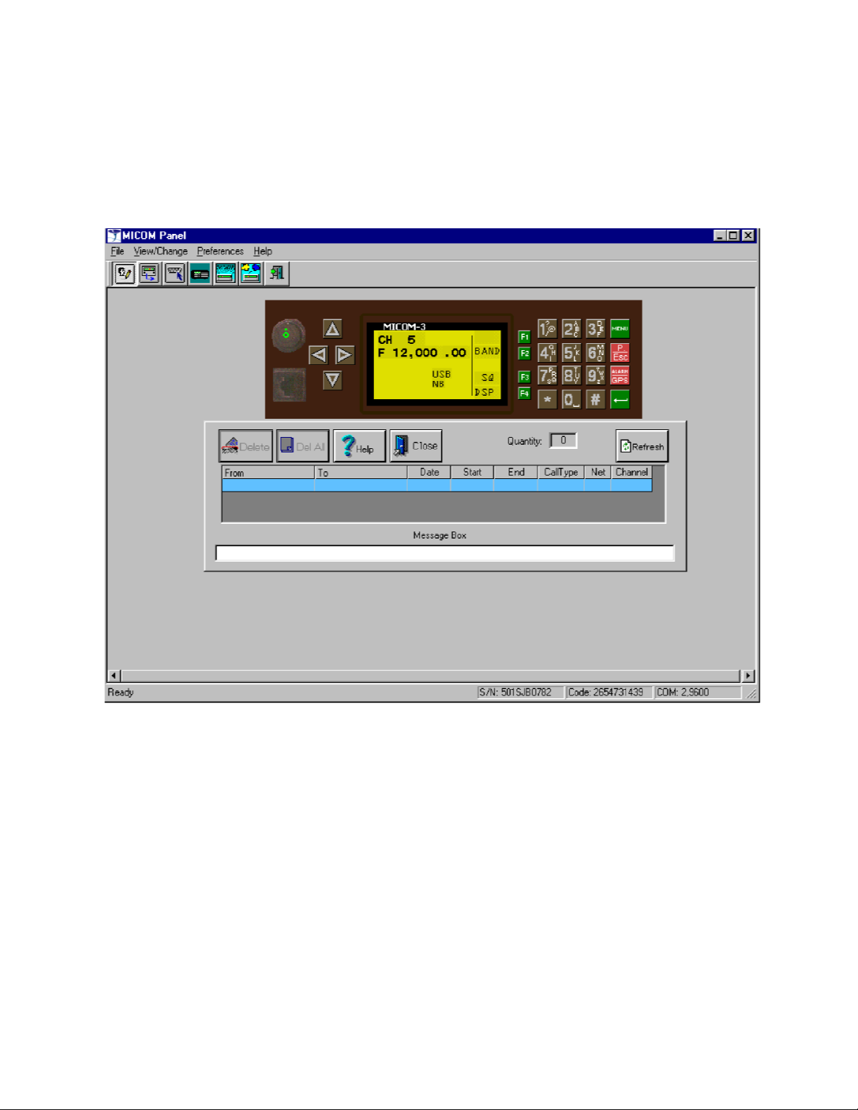
MICOM-3 Panel
Displays a mimic of the MICOMmouse and keyboard. Offers a simple, clear way of simulating the
operations, as a replacement for the Computer Interface Panel,
in accordance with the MICOM-3F/3T/3R Owner’s Guide (6886867J01).
Stores information on calls sent and received in a log file. The file can be saved, edited and
printed as necessary.
1

MICOM-3 PC Control & Programming Owner’s Guide
H ow to …
With the MICOM Radio Control application, you can handle two types of tasks:
x Configuration: “read” (upload) existing radio configuration, change radio configuration, and “write”
(download) the new/changed configuration to the radio. Any configuration data (whether raw
configuration read from the radio, modified configuration data, or a completely new
configuration prepared on the computer) can be stored as files on the computer disk, for
backup, documentation, planning, and reuse; file contents can also be printed in human-
readable format on a printer connected to the computer.
x Operation: operate the radio with the computer mouse and keypad. Log files record the calls
handled by the radio; you can delete calls from the log as required; you can also store log files as
disk files, and print them.
Configuration Tasks
Configuration tasks are performed with the RSS Panel and RSS ALE Panel.
Reading and writing the radio and ALE parameters databases expedites the configuration of radios
used in a common environment. Alternative configurations for different missions can be prepared
ahead, and rapidly downloaded to the radios as required.
x In a typical (on-line) scenario, you would connect a radio to the computer, read its radio and ALE
databases and store them as files. Using these files, you would create files for other radios, or
files for use in other circumstances. After the files are ready, you can open the appropriate file,
and then “write: the parameters to the radio, as required. When working with only one radio,
you may leave the radio connected and switch to the Computer Interface Panel or the MICOM
Panel, to work with the radio from the computer.
Note Group configuration data for use in the SCAN mode must be prepared on the
computer, and then written to the radio.
x Alternately, you can prepare complete configurations off-line, using the RSS Panel and RSS ALE
Panel configuration functions. In this case, you do not need to connect the computer running
the MICOM Radio Control application to a radio until you are ready to program it, or want to
operate it from the computer.
The MICOM Radio Control application automatically performs extensive validity checks that ensure
the parameters prepared by you are consistent. Any incorrect or out-of-range entry is therefore
immediately detected and reported in clear language in a pop-up information box or in the prompt
and help line of the corresponding screen. All the configuration errors are recorded in a special file
(the configuration check file), which can be displayed and analyzed to find the causes for
inconsistency. You can program a radio only after all the detected errors have been corrected.
Operation
You can operate the radio with the Computer Interface Panel or the MICOM Panel. With these
panels, you can also change the current channel parameters or operating mode, just as you would
be able to do when using the radio front panel.
11

Installation
Contents of PC Control and Programmin
g Package
If you are new to the Windows operating environment, take the opportunity to learn Windows
Installation
Check that you have received the following items:
1. MICOM Radio Control (MRC) application software, supplied on a CD.
2. This Owner’s Guide.
3. Programming cable (connects 9-pin D-type PC serial communication port to the 44-pin
accessories connector of the radio).
Minimum Computer Requirements
The MICOM Radio Control (MRC) application softwarerequires a personal computer running
Microsoft Windows® 95 and later versions up to Windows® XP.
Windows must be able to run properly on the computer before the MRC application is installed.
Additional minimum requirements include:
x Monitor: minimum resolution of 800x600, and at least 256 colors.
Note MRC screens are designed to fill the screen at the 800x600 resolution, and wil
display properly with 256 colors. However, higher resolutions and color depth
can be used.
x Free hard disk space of at least 12 Mbytes x
One CD drive
x One serial communication port (COM1 or COM2; using an USB edge port, which adds 4
serial ports, increases the range of ports that can be used to COM1 to COM6)
x A mouse.
A printer is also recommended, becauseit may be used to generatehardcopies of radio
configuration data, and other files created by the MICOM Radio Control application.
Before you Start …
To install and use the MICOM Radio Control application, you need a basic working knowledge of
Microsoft Windows.
fundamentals –using the mouse, working with windows, and opening and closing documents –
before you begin to work with the MICOM Radio Control application.
You may find the required information in the Windows User’s Reference Guide for your Windows
version, available from Microsoft. See also the Getting Started section.
1

MICOM-3 PC Control & Programming Owner’s Guide
9.
Before continuing,remove t
he installation CD from the computer’s CD drive. It is
tart. Before the main window
is displayed, you will see a logo screen that displays the name and version of the MICOM Radio
Installation Procedure
Before starting the installation:
1. If necessary, turn the computer on and wait until Windows starts.
2. Before starting the installation, make sure to close any other application.
To install the MICOM Radio Control application:
1. Insert the CD with the MICOM Radio Control application in the computer’s CD drive.
2. Open the Windows Start menu, and select Run.
3. Click the Browse button,display the files in the CD root directory, and find
the file MRCVV_setup.exe (VV is the MICOM Radio Controlapplication version
number).
4. Double-click on the file name: the name will be copied to the Open field.
5. Click the OK button in the Run window: the installation program starts.
6. FollowtheinstructionsonthescreentoinstalltheMICOMRadioControlapplication.Accept
7. After the installation is successfully completed, an MRC icon will
be placed on your desktop.
recommended to restart your computer.
This completes MICOM Radio Control application installation.
To test for proper installation:
Double-click the MRC icon: the MICOM Radio Control application will s
Control application.
Note After being started, the MICOM Radio Control application displays the Computer
Interface Panel window, and tries to establish communication with a MICOM-3
radio, which is possible only when a radio is connected, as explained in the
Quick Start section on the next page. Therefore, ignore any messages that
may be displayed.
To end the application, select Exit on the File menu.
13
Getting Started
ial
communication port of the computer. You may use any free port in the range of COM1 to
(page 4), and then
attempts to read the radio database. If you are using any port except the default (COM 1), this
Communication
out of four
Getting Started
Before You Begin Working
If you are not familiar with using the mouse or keyboard, or with choosing commands in Windows,
first read the information in the General Procedures section.
If you are familiar with Windows, use the Quick Start to start working.
Quick Start
Preliminary Steps
Skip Steps 1, 2, 5 if you intend to work off-line (without connecting to a radio).
1. Connect the supplied cable from the 44-pin accessories connector of the radio to a ser
COM6.
2. Turn the radio on.
3. Start the MICOM Radio Control application, for example, by double-clicking its icon.
4. After application starts, it displays the Computer Interface Panel
will fail and you must first configure the required port as explained in the
Port Configuration section below.
5. If the connectionto the radio is successfully made, wait for its databases to be read.
The Computer Interface Panel window is then updated with the current radio state.
6. You may now change the MICOM Radio Control function (panel): open the View/Change
menu of the Computer Interface Panel window and click the desired panel name.
7. For the RSS Panel and RSS ALE Panel, you may use the Open item on the File menu to
load a desired parameters file from the computer disk.
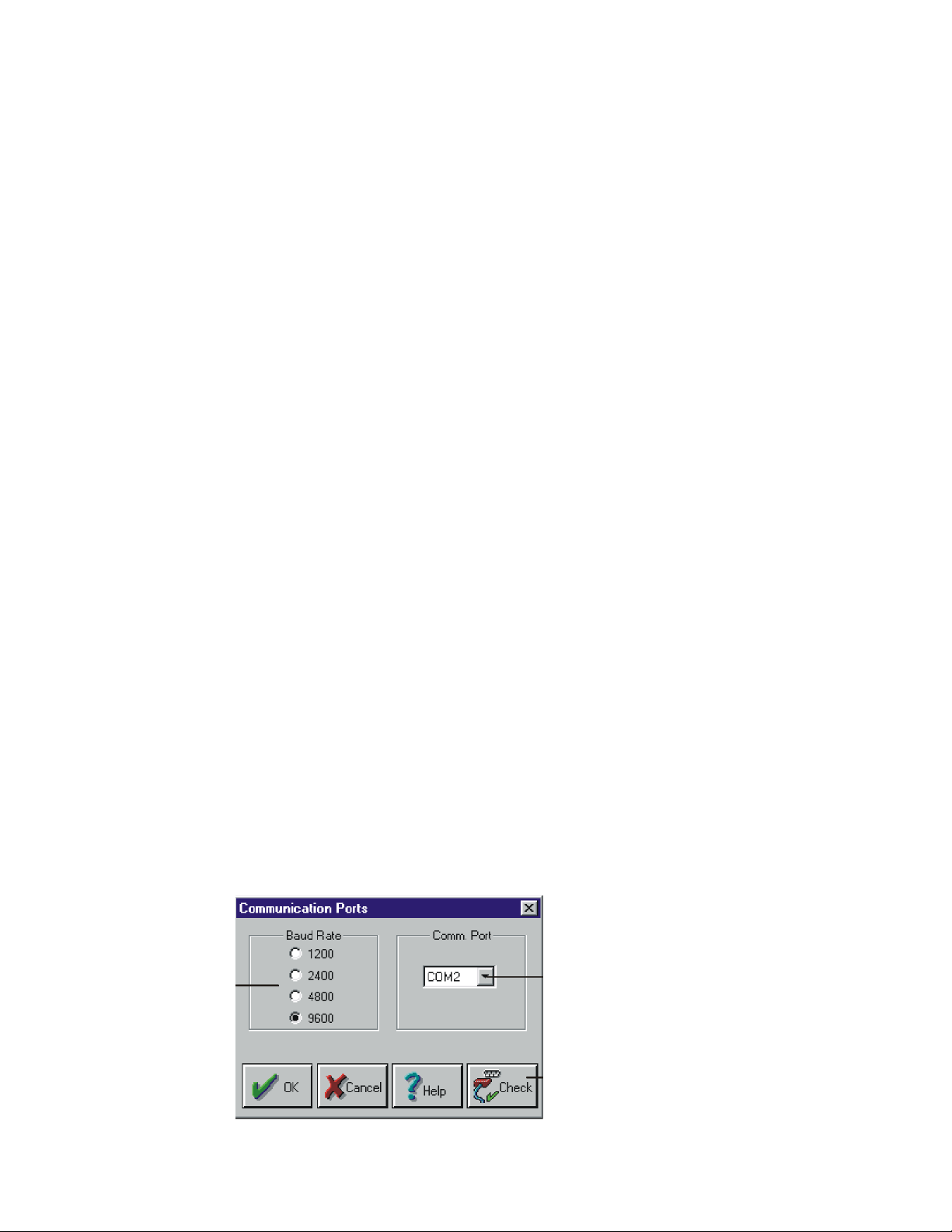
Communication Port Configuration
1. In the Computer Interface Panel window (or any panel you have opened), open the
Preferences menu and click the Comm Ports item.
2. Make the required selections in the Communication Ports dialog box, and then click OK
to confirm.
Selects one
baud rates.
Click to see the drop-down list and
select a communication port.
Click to test radio-PC
communication using
the selected communication
port and baud rate.
1
MICOM-3 PC Control & Programming Owner’s Guide
Control
application. If you are not familiar with using the mouse or keyboard, or with choosing commands in
Choosing a command tells the MICOM Radio Control application what to do next: to load
rameters from the radio, to program radio parameters, and so on. Commands that carry out
menu contains commands you use to
enu bar at the top of the
You can use the mouse or the keyboard to display the commands on each menu. To open the
menus and browse through the commands, drag across the menu bar with the mouse, or press the
is
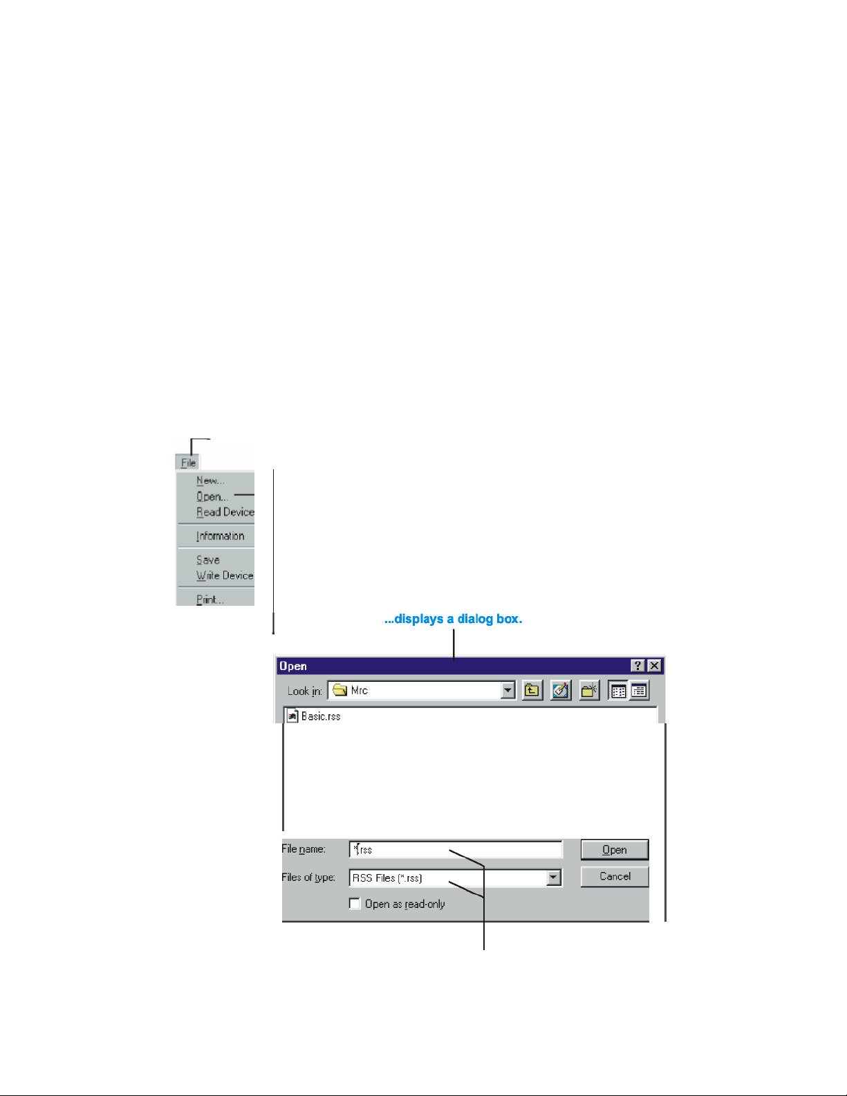
Open the File menu to display these comm
ands.
General Procedures
You can use the keyboard or the mouse to carry out any action in the MICOM Radio
Windows, read the following information.
Menus and Commands
pa
similar actions are grouped on a menu. For example, the File
load, save and print the radio parameters. The menus are listed on the m
MICOM Radio Control application window.
ALT key, and then press the underlined letter in the name of the menu you want to open.
The MICOM Radio Control application carries out some commands right away. If more information
needed to complete a command, the MICOM Radio Control application displays a dialog box. You
select options in the dialog box to control how the command is carried out.
When an ellipsis follows a command name,
choosing the command...
Select options in the dialog box to specify
how the commands are carried out.
Figu re 1 . Fi le Me nu a nd O pen Dial og Bo x
15
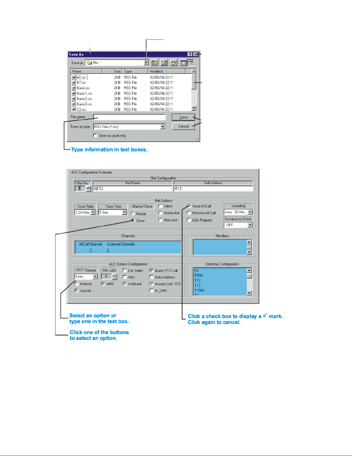
Move the dialog box
by dragging the title bar.
If
the arrow
is
attached to
the
list,
select an option.
Choose a command button
to carry out an action.
Getting Started
Double-click the box
Select items from list boxes. Use the
scroll bars to view items not visible.
Figure 2. Dialog Box Options
16
MICOM-3 PC Control & Programming Owner’s Guide
3 radio from a remote or
local location, using a personal computer. This is the panel that opens when you start the
MICOM Radio Control Application Windows
This section describes the main elements of the MICOM Radio Control application windows and
introduces terms used in this documentation.
The MICOM Radio Control application has four functions, each displaying a different panel:
x Computer Interface Panel (page 4): enables controlling the MICOM-
MICOM Radio Control application.
x RSS Panel (page 2): used to program the features and operational parameters of the radio for
operation in all the modes except ALE.
x RSS ALE Panel (page 3): used to program the features and operational parameters of the
radio for operation in the ALE mode.
x MICOM Panel (page5): mimicof the MICOM-3 panel for directlycontrollingthe radio using
the computer mouse and keyboard.
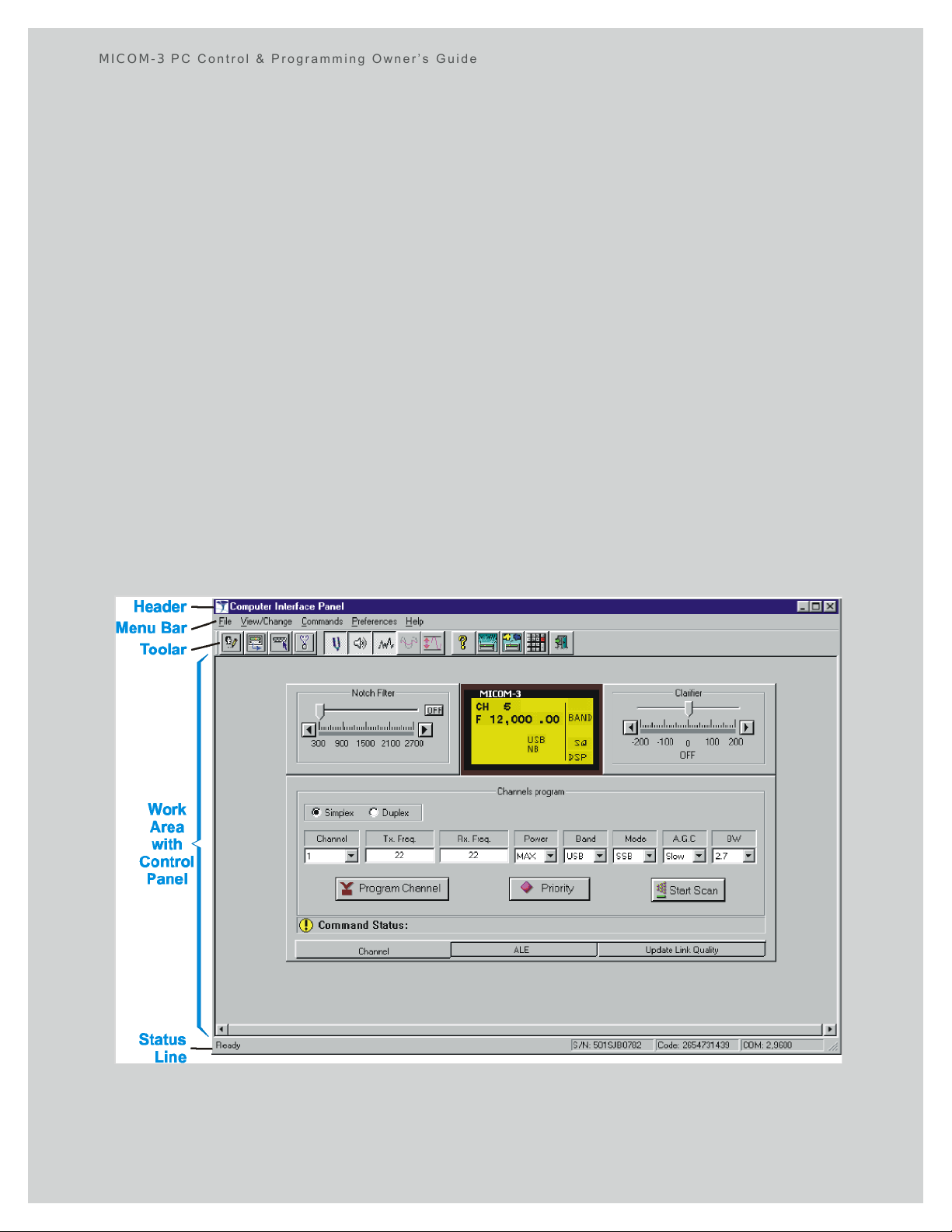
Panel Elements
Each panel has the following elements (from top to bottom):
x Header –standardWindows window header, displays the panel name
x Menu bar –depends on the open panel
x Toolbar –depends on the open panel
x Work area –displays various windows (for example, a control panel), and dialog boxes •
Status bar.
Figure 3. Elements of MICOM Radio Control Application Panels
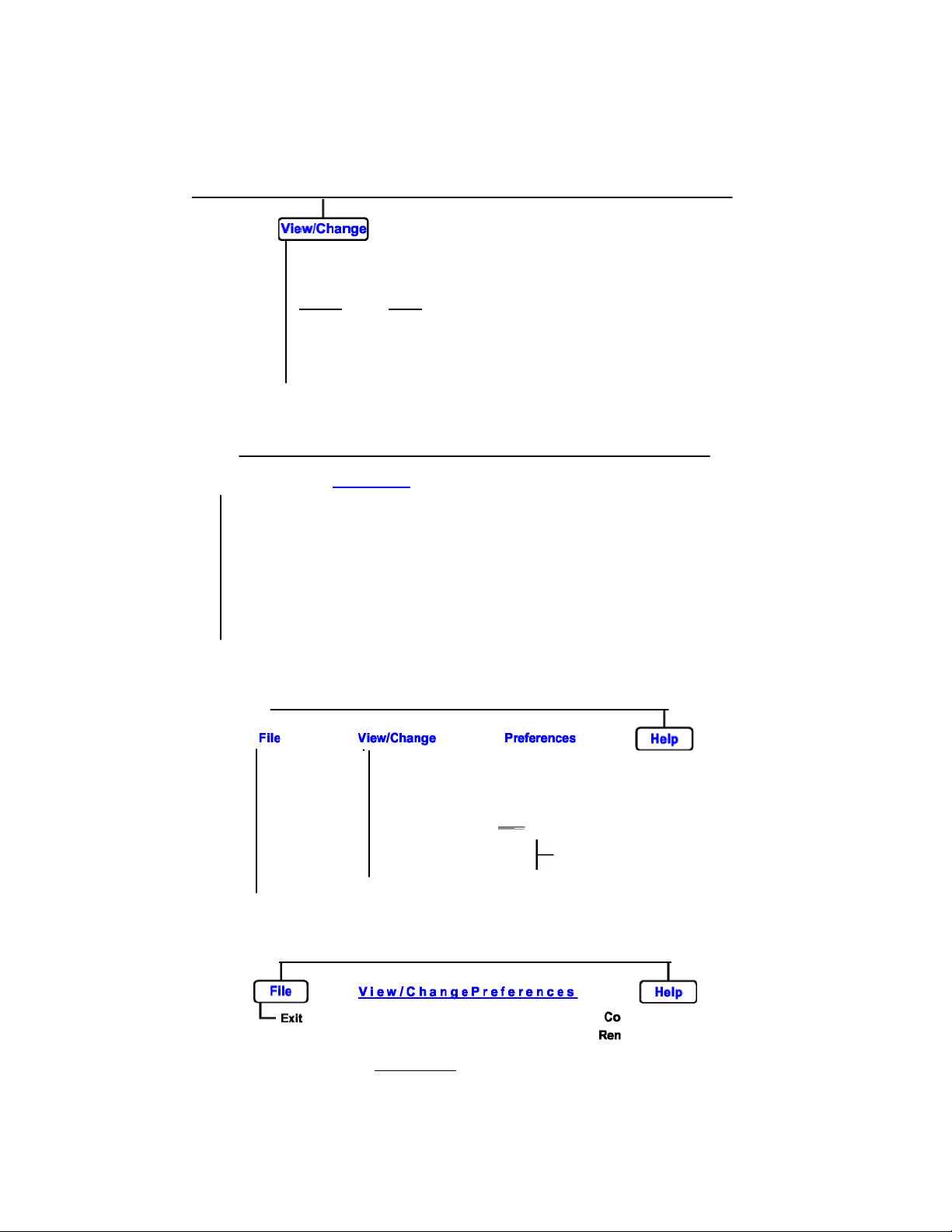
The Menu Bars
The MICOM Radio Control application commands are listed on menus. The menus are listed on
long the upper edge of the application window: select (highlight) a menu and then
RSS Panel
Squelch on
Comm. Ports...
Figure 4.
Computer Interface Panel
Menu Bar
New
RSS Panel
New
RSS Panel
RSS Panel
the menu bar a
choose a command from that menu. Choosing the command carries out the action.
Getting Started
Read Device
Exit
File View/Change Service
Open RSS ALE Panel
Read Device Computer Interface
Information MICOM Panel
Save Configuration Channels...
Write Device Radio WideInformation Groups...
Print ConfigurationCheck
Exit
RSS ALE Panel
9 Computer Interface
MICOM ______Panel
Clarifi
er
Log File
Stack
9
Monitor on Remote Control
Noise Blanker on
Attenuator on
Clipper on
Reset
Figure 5. RSS Panel Menu Bar
BITE
PreferencesCommands
Preferences Help
Comm. Ports... Remote
Control
HelpFile
Contents
About
Open
Read Device
Information
Save
Write Device
Print
Exit
Figure 6. RSS ALE Panel Menu Bar
Figure 7. MICOM Panel Menu Bar
9 RSS ALE Panel
Computer Interface
MICOM Panel
Configuration
RadioWideInformation
Configuration Check Auto Dial
RSS ALE Panel
Computer Interface
9MICOM Panel
___________Log
Comm. Ports...
Remote Control
Directory...
Messages...
14
MICOM-3 PC Control & Programming Owner’s Guide
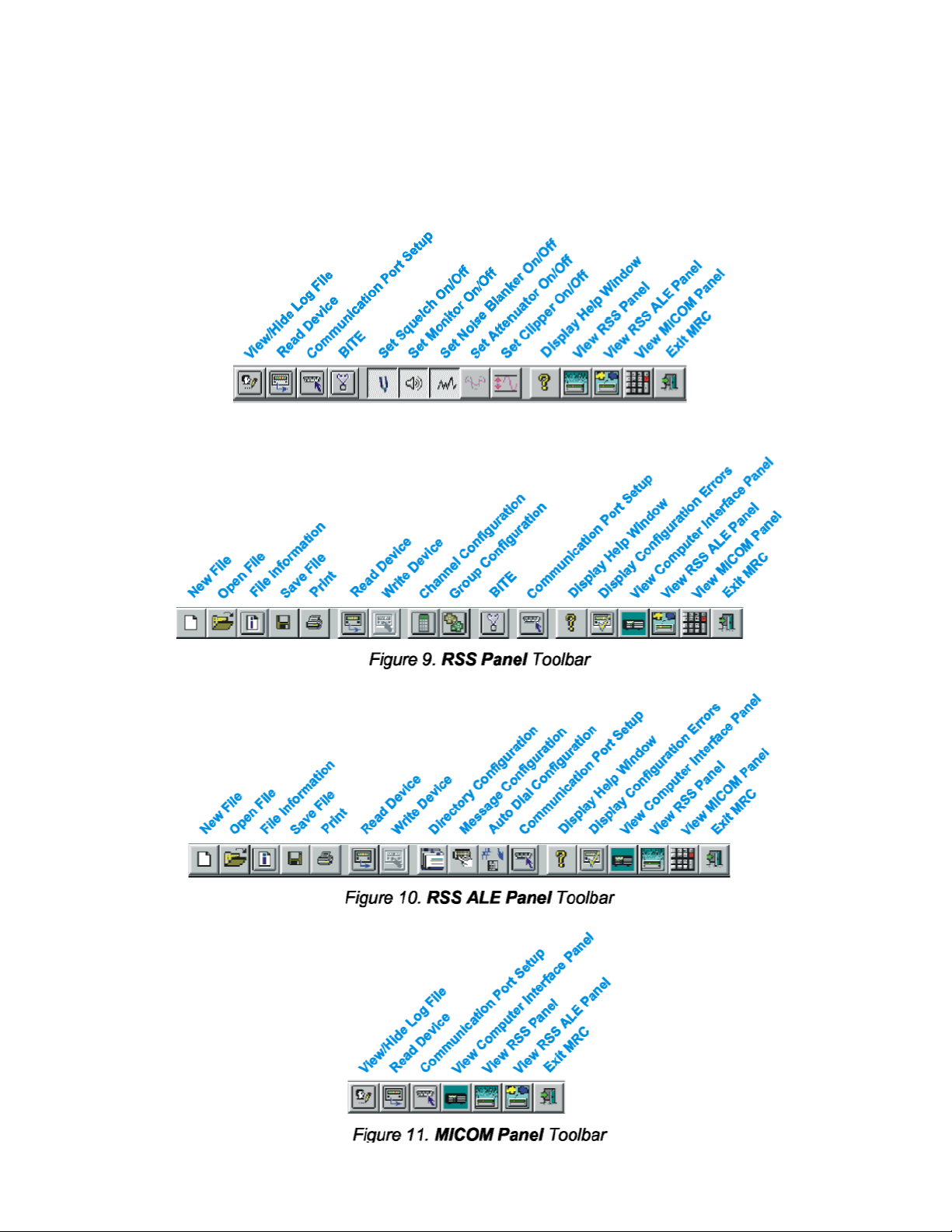
The Toolbar, displayed just below the menu bar, has buttons that provide quick access to commonly
d commands. The button background changes when clicked, to indicate the corresponding
command is active. When the pointer is located on the bottom edge of each toolbar button, the
bottom status line is
The Toolbars
use
button name appears underneath it. At the same time, the help prompt in the
updated.
Figure 8. Computer Interface P anel Toolbar
15
 Loading...