

Page 1
FEATURES/ADVANTAGES
MODEL I
8 APCO 16 Compliant Trunking
Offers standard SMARTNET features for advanced
functionality.
8 Companion Product to the
MTS 2000™ Portable
Permits easy transfer of operational knowledge as
users alternate between mobiles and portables.
8 Standard 48 Modes
With up to 150 mode options to meet your
system needs.
8 Data Capability
Expands your communications capabilities.
8 8 Character Alphanumeric Display with
Indicators
For easy to read information that is illuminated for
clearer visibility.
8 5 Programmable Buttons
Allows you to program your radio to meet your
business needs.
8 Removable Control Head Buttons
Allows you the flexibility to locate your radio control
head buttons based on your preferences.
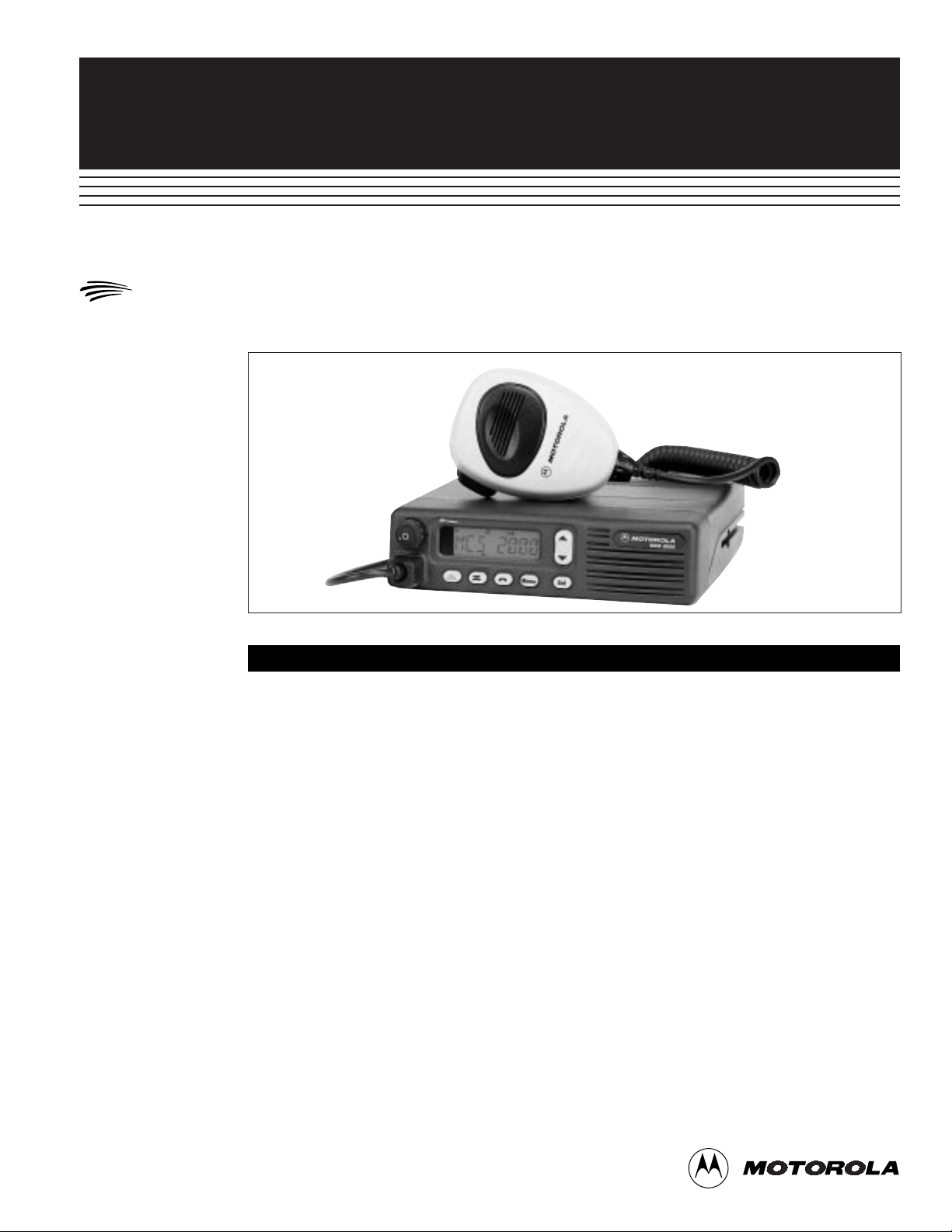
MCS 2000TMMOBILE
MODEL I
MCS 2000
8
VHF/UHF
800/900 MHz
The MCS 2000™ Model I is Motorola’s state-of-the art mobile radio solution, ergonomically designed to meet your
communication demands.
The MCS 2000 mobile uses Motorola’s FLASHport
®
technology. FLASHport gives you the ability to choose a
radio that meets your needs today, then upgrade for increased flexibility and control as your needs change. You
can easily add the latest features to your existing system or upgrade to new operating system packages as they
become available. This helps prevent obsolescence by extending the useful life of your investment.
Model I
FLASHport
TM
8 Dual Mode Operation
Provides you with the flexibility of Conventional and
Trunked features.
8 Telephone Interconnect Preprogrammed List
Allows you to program up to 10 telephone
numbers in your mobile.
8 Private Call and Call Alert
Can be programmed for up to 10 radio IDs.
8 Status/Message List
Allows for 4 Status/8 Message programming to permit you to quickly send information to the dispatcher.
8 Remote or Dash Mounting
Permits optimal use of limited vehicle space.
8NPSPAC Frequency Operation
Allows you to operate on 821-824 MHz frequencies.
8 FourProgrammable One-Touch Buttons
(Optional)
Allows you to select the trunking features you
need with the touch of a button.
8 SECURENET Digital Encryption Capability
Allows confidential communications when added to
your radio. (Not available in 900 MHz models)
Page 2
Encryption Type: Digital
Coding Method: Multi-register non-linear combiner
Synchronization: Self synchronizing or counter addressing
Code Key Initialization: Internally derived pseudo-random initializing vector
Code Key Generation: External hand held microprocessor controlled key variable loader
Code Storage: Volatile electronic memory
Analog to Digital
Conversions: Continuously variable Slope Delta Modulation
Voice Sample Rate: 12 kBit/Sec
SECURITY
800 MHz 900 MHz VHF (1-25W) UHFI (10-25W) UHFII (10-20W)
Channel Spacing: 25 kHz 12.5 kHz 12.5/30 kHz 12.5/25 kHz 12.5/25 kHz
Frequency Stability
(PPM) of assigned
center frequency
–30º to +60º
degrees C
ambient: 851-866 MHz: ±2.5 935-941 MHz: ±1.5 136-174 MHz: ±2.0 403-450 MHz: ±2.0 450-512 MHz: ±2.0
806-821 MHz: ±2.5 896-902 MHz: ±1.5
866-869 MHz: ±1.5
821-824 MHz: ±1.5
Modulation
Limiting
: 851-866 MHz: 5.0 kHz 935-941 MHz: 2.5 kHz 5/2.5 kHz 5/2.5 KHz 5/2.5 KHz
806-821 MHz: 5.0 kHz 896-902 MHz: 2.5 kHz
866-869 MHz: 4.0 kHz
821-824 MHz: 4.0 kHz
Data Mode System
Deviation (kHz)
SECURENET 12 KB: 800 MHz: 4.0 kHz N/A 4.0 kHz 4.0 kHz 4.0 kHz
821-824 MHz: 2.4 kHz
Audio Distortion: 3% 3% 3% 3% 3%
Audio Response: +1 to –3 dB +1 to –3 dB +1 to –3 dB +1 to –3 dB +1 to –3 dB
Conducted Spurious
Emissions: –70 dBc –65 dBc –80 dBc –80 dBc –80 dBc
Radiated Spurious
Emissions: –13 dBm –13 dBm –13 dBm –13 dBm –13 dBm
Output Impedance: 50 Ohms 50 Ohms 50 Ohms 50 Ohms 50 Ohms
Modulation: 800 15W 900 12W
16K0F3E*, 16K0F1D*, 11K0F1D, 11K0F2D, 16K0F3E 16K0F3E 16K0F3
16K0F2D*, 15K0F2D*, 11K0F3E 11K0F3E 11K0F3E 11K0F3E
14K0F3E, 20K0F1E, 20K0F1E 20K0F1E 20K0F1E
14K0F1D, 14K0F2D 16K0F2D 16K0F2D 16K0F2D
16K0F1D 16K0F1D 16K0F1D
800 15W 900 30W
16K0F3E*, 16K0F1D, 10K0F1D, 11K0F2D,
20K0F1E, 14K0F1D, 11K0F3E
14K0F2D, 14K0F3E,
11K6F2D, 13K8F1D
Audio Sensitivity
for 60% max. dev.
@ 1000 Hz: 0.080V ±3 dB 0.080V ±3 dB 0.080V ±3 dB 0.080V ±3 dB 0.080V ±3 dB
FM Hum and Noise: –40 dB –40 dB 12.5 kHz: –39 dB 12.5 kHz: –39 dB 12.5 kHz: –39 dB
30 kHz: –45 dB 25 kHz: –45 dB 25 kHz: –45 dB
Maximum Freq.
Separation: 18 MHz 6 MHz 38 MHz 47 MHz 62 MHz
TRANSMITTER
Page 3

800 MHz 900 MHz VHF (1-25W) UHFI (10-25W) UHFII (10-20W)
Channel Spacing: 25 kHz 12.5 kHz 12.5/30 12.5/25 12.5/25
Sensitivity(µV):
12 dB Sinad: .30 .30 .30 .30 .30
20 dB Quieting: .40 .40 .40 .40 .40
Adjacent Channel
Selectivity: –75 dB –65 dB 12.5 kHz: –65 dB 12.5 kHz: –60 dB 12.5 kHz: –60 dB
30 kHz: –80 dB 25 kHz: –75 dB 25 kHz: –75 dB
Intermodulation: –75 dB –65 dB –70 dB –70/–80 dB –70/–80 dB
Spurious & Image
Rejection: –75 dB –70 dB –80 dB –80 dB –80 dB
Rated Audio: 4W Internal Speaker 4W Internal Speaker 4W Internal Speaker 4W Internal Speaker 4W Internal Speaker
7.5W/13W External 7.5W/13W External 7.5W/13W External 7.5W/13W External 7.5W/13W External
Speaker Speaker Speaker Speaker Speaker
Cond/Radiated
Emissions: FCC Part 90 FCC Part 90 FCC Part 90 FCC Part 90 FCC Part 90
Max. Freq.
Separation: 18 MHz 6 MHz 38 MHz 47 MHz 62 MHz
Frequency Stability
(PPM) of assigned
center frequency
–30º to +60º C
ambient: 851-866 MHz: ±2.5 ±1.5 ±2.0 ±2.0 ±2.0
866-869 MHz: ±1.5
Input Impedance: 50 Ohms 50 Ohms 50 Ohms 50 Ohms 50 Ohms
Audio Output: 4W @ 3% distortion 4W @ 3% distortion 4W @ 3% distortion 4W @ 3% distortion 4W @ 3% distortion
Optional: 7.5W @ 3% distortion 7.5W @ 3% distortion 7.5W @ 3% distortion 7.5W @ 3% distortion 7.5W @ 3% distortion
Optional: 13W @ 5% distortion 13W @ 5% distortion 13W @ 5% distortion 13W @ 5% distortion 13W @ 5% distortion
RECEIVER
Dimensions: 5˝ H x 5˝ W x 2.7˝ D
Weight: 20.4 ounces
SPEAKER (Optional) 7.5W/13W
25W VHF Type Acceptance Number: AZ492FT3791
25W UHF R1 Type Acceptance Number: AZ492FT4819
20W UHF R2 Type Acceptance Number: AZ492FT4820
15W 800 MHz Type Acceptance Number: AZ492FT5765
35W 800 MHz Type Acceptance Number: AZ492FT5773
12W 900 MHz Type Acceptance Number: AZ492FT5766
30W 900 MHz Type Acceptance Number: AZ492FT5780
For additional environment specification information refer to the MIL-STD 810 document R0-1-193.
* Emissions are not applicable for frequency band 821-824 and 866-869 MHz.
NOTE: The MCS 2000 Model I Specifications are Typical Performance Specifications
FCC INFORMATION
Page 4

806-869 MHz 806-869 MHz 896-941 MHz 896-941 MHz VHF: 136-174 MHz UHFI: 403-450 MHz UHFII: 450-512 MHz
15W 35W 12W 30W 1-25W 1-25W 10-20W
Model I: M01UGL6PW4_N M01UJL6PW4_N M01WGL4PW4_N M01WJL4PW4_N M01KHL9PW4_N M01RHL9PW4_N M01SHL9PW4_N
Motorola U.S.A. Motorola Canada Limited
1301 E. Algonquin Road 3900 Victoria Park Avenue
Schaumburg, Illinois 60196 North York, Ontario M2H 3H7
In the U.S. call: 1-800-247-2346 In Canada call: 1-800-268-5758
Outside the U.S. and Canada call: (847) 538-6602
, Motorola, MCS 2000, MTS 2000, SMARTNET, SmartZone and
FLASHport are trademarks of Motorola.
■ ©1997 by Motorola Inc.
■ Printed in U.S.A. ■ (9708) Merit ■ Produced by Customer
Communications.
Motorola is an Equal Employment Opportunity/Affirmative
Action Employer
MCS 2000
Model I
R3-1-172D
SPECIFICATIONS
STANDARD SPECIFICATIONS
Support Services
Wherever Motorola sells,
our product is backed by
service. Our products are
serviced throughout the
world by a wide network
of company or authorized
independent distributor
service organizations.
Channel Capability: Standard: 48
Optional: 150
Weight: 1-25W: 3.89 lbs
10-15W: 3.89 lbs
30-35W: 4.04 lbs
Dimensions: Transceiver VHF & UHF: 1.73˝ H x 6.61˝ W x 6.31˝ D
Transceiver 10-15W 800 & 900: 1.73˝ H x 6.61˝ W x 6.31˝ D
Transceiver 30-35W 800 & 900: 1.73˝ H x 6.61˝ W x 7.76˝ D
Control Head-Dash Mt: 1.75˝ H x 6.61˝ W x 1.81˝ D
Metering: All adjustments and alignments are performed electronically using an IBM Personal Computer, a Radio Interface Box (RIB)
and Field Maintenance Software.
Standby @ 13.8 (open): .55A
Transmit at Rated Power:
800 MHz 15W: 6.5A
35W: 13.5A
900 MHz 12W: 6.5A
30W: 14.5A
VHF 1-25W: 9.5A
UHF I 10-25W: 9.5A
UHF II 10-20W: 9.5A
Maximum Battery Drain Received
@ 4W Rated Audio @ 13.8V: 1.5A
Operation: 12V DC Negative Ground
GENERAL SPECIFICATIONS
Specifications subject to change without notice.
The VHF & UHF 25W mobiles meet only those durability specs shaded in gray. The 800 and 900 MHz mobiles meet all the durability specs listed.
US Military Spec 810C US Military Spec 810D US Military Spec 810E
Low Pressure 500.1 Proc I 500.2 Proc I 500.3 Proc II
High Temperature Storage 501.1 Proc I 501.2 Proc I Cat A1 501.3 Proc I Cat A1
High Temperature Operational 501.1 Proc II 501.2 Proc II Cat A1 501.3 Proc II Cat A1
Low Temperature Storage 502.1 Proc I 502.2 Proc I Cat C1 502.3 Proc I Cat C1
Low Temperature Operational 502.1 Proc II 502.2 Proc II Cat C1 502.3 Proc II Cat C1
Temperature Shock 503.1 Proc I 503.2 Proc I 503.3 Proc I
Solar Radiation 505.1 Proc I 505.2 Proc I 505.3 Proc I
Rain Blowing 506.1 Proc I 506.2 Proc I 506.3 Proc I
Rain Steady 506.1 Proc II 506.2 Proc II 506.3 Proc II
Humidity Cycling 507.1 Proc II 507.2 Proc II 507.3 Proc II
Salt Fog 509.1 Proc I 509.2 Proc I 509.3 Proc I
Dust Blowing Dust 510.1 Proc I 510.2 Proc I 510.3 Proc I
Dust Blowing Sand 510.2 Proc II 510.3 Proc II
Vibration Minimum Integrity 514.2 Proc I 514.3 Proc I Cat 10 514.4 Proc I Cat 10
Vibration Loose Cargo Transport 514.2 Proc XI 514.3 Proc II Cat 3 514.4 Proc I Cat 3
Shock Functional 516.2 Proc I 516.3 Proc I 516.4 Proc I
Shock Bench Handling 516.2 Proc V 516.3 Proc VI 516.4 Proc VI
Shock Crash Hazard 516.2 Proc III 516.3 Proc V 516.4 Proc V
Vibrational Sinusoidal 514.2 Proc VIII
DURABILITY
CUSTOMER
Communications
SERVICE
 Loading...