


For:char
Printed on:Mon, Feb 6, 1995 09:48:35
From book:DL121CH4 (5) VIEW
Document:MC74F350 (5) VIEW
Last saved on:Fri, Feb 3, 1995 16:04:28
4-153
FAST AND LS TTL DATA
4-BIT SHIFTER
(With 3-State Outputs)
The MC54/74F350 is a specialized multiplexer that accepts a 4-bit word
and shifts it 0, 1, 2 or 3 places, as determined by two Select (S0, S1) inputs.
For expansion to longer words, three linking inputs are provided for lower-order bits; thus two packages can shift an 8-bit word, four packages a 16-bit
word, etc. Shifting by more than three places is accomplished by paralleling
the 3-state outputs of different packages and using the Output Enable (OE
)
inputs as a third Select level. With appropriate interconnections, the F350 can
perform zero-backfill, sign-extend or end-around (barrel) shift functions.
• Linking Inputs for Word Expansion
• 3-State Outputs for Extending Shift Range
FUNCTIONAL DESCRIPTION
The F350 is operationally equivalent to a 4-input multiplexer with the inputs
connected so that the select code causes successive one-bit shifts of the data
word. This internal connection makes it possible to perform shifts of 0, 1, 2 or
3 places on words of any length.
A 7-bit data word is introduced at the In inputs and is shifted according to
the code applied to the select inputs S0, S1. Outputs O0–O3 are 3-state, controlled by an active-LOW output enable (OE
). When OE is LOW, data outputs
will follow selected data inputs; when HIGH, the data outputs will be forced to
the high-impedance state. This feature allows shifters to be cascaded on the
same output lines or to a common bus. The shift function can be logical, with
zeros pulled in at either or both ends of the shifting field; arithmetic, where the
sign bit is repeated during a shift down; or end around, where the data word
forms a continuous loop.
LOGIC EQUATIONS
O0 = S
0 S1 I0
+ S0 S1 l–1 + S0 S1 I–2 + S0 S1 I
–3
O1 = S
0 S1 I1
+ S0 S1 I0 + S0 S1 l–1 + S0 S1 I
–2
O2 = S
0 S1 I2
+ S0 S1 I1 + S0 S1 I0 + S0 S1 I
–1
O3 = S
0 S1 I3
+ S0 S1 I2 + S0 S1 I1 + S0 S1 I
0
TRUTH TABLE
Inputs Outputs
OE S
1
S
0
O
0
O
1
O
2
O
3
H X X Z Z Z Z
L L L I
0
I
1
I
2
I
3
L L H I
–1
I
0
I
1
I
2
L H L I
–2
I
–1
I
0
I
1
L H H I
–3
I
–2
I
–1
I
0
H = HIGH Voltage Level Z = High Impedance
L = LOW Voltage Level X = Immaterial
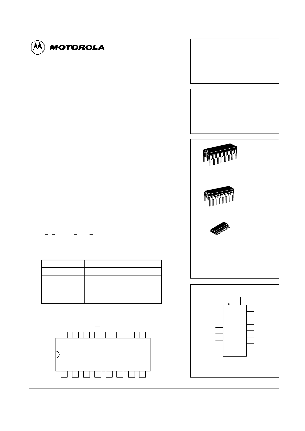
MC54/74F350
4-BIT SHIFTER
(With 3-State Outputs)
FAST SCHOTTKY TTL
J SUFFIX
CERAMIC
CASE 620-09
N SUFFIX
PLASTIC
CASE 648-08
16
1
16
1
ORDERING INFORMATION
MC54FXXXJ Ceramic
MC74FXXXN Plastic
MC74FXXXD SOIC
16
1
D SUFFIX
SOIC
CASE 751B-03
LOGIC SYMBOL
VCC = PIN 16
GND = PIN 8
13 9 10
1
2
3
4
5
6
7
15
14
12
11
OE
O
0
O
1
O
2
O
3
I
–3
I
–2
I
–1
I
0
I
1
I
2
I
3
S1S
0
CONNECTION DIAGRAM
14 13 12 11 10 9
1 2 3 4 5 6
7
16 15
8
V
CC
I
–3
O0O1OE
O
2
S
0
O
3
S
1
I–2I
–1I0I1I2I3
GND

4-154
FAST AND LS TTL DATA
MC54/74F350
LOGIC DIAGRAM
I
–3
I
–2
I
–1
I0I1I2I
3
S
1
S0OE
O
0
O
1
O
2
O
3
GUARANTEED OPERATING RANGES
Symbol Parameter Min Typ Max Unit
V
CC
Supply Voltage 54, 74 4.5 5.0 5.5 V
54 –55 25 125
TAOperating Ambient Temperature Range
74 0 25 70
°C
I
OH
Output Current — High 54, 74 — — –3.0 mA
I
OL
Output Current — Low 54, 74 — — 24 mA
DC CHARACTERISTICS OVER OPERATING TEMPERATURE RANGE (unless otherwise specified)
Limits
Symbol
Parameter
Min Typ Max
Unit
Test Conditions
V
IH
Input HIGH Voltage 2.0 V Guaranteed Input HIGH Voltage
V
IL
Input LOW Voltage 0.8 V Guaranteed Input LOW Voltage
V
IK
Input Clamp Diode Voltage –1.2 V IIN = –18 mA VCC = MIN
54, 74 2.4 3.3 V IOH = –3.0 mA VCC = 4.5 V
VOHOutput HIGH Voltage
74 2.7 3.3 V IOH = –3.0 mA VCC = 4.75 V
V
OL
Output LOW Voltage 0.35 0.5 V IOL = 24 mA VCC = MIN
I
OZH
Output OFF Current — HIGH 50 µA V
OUT
= 2.7 V VCC = MAX
I
OZL
Output OFF Current — LOW –50 µA V
OUT
= 0.5 V VCC = MAX
20
VIN = 2.7 V
IIHInput HIGH Current
100
µA
VIN = 7.0 V
VCC = MAX
I
IL
Input LOW Current –1.2 mA VIN = 0.5 V VCC = MAX
I
OS
Output Short Circuit
Current (Note 2)
–60 –150 mA V
OUT
= 0 V VCC = MAX
I
CCH
22 35
Outputs HIGH
I
CCL
Power Supply Current
26 41
mA
Outputs LOW
VCC = MAX
I
CCZ
26 42 Outputs OFF
CC
= MAX
NOTES: 1. For conditions such as MIN or MAX, use the appropriate value specified under guaranteed operating ranges.
NOTES: 2. Not more than one output should be shorted at a time, nor for more than 1 second.

4-155
FAST AND LS TTL DATA
MC54/74F350
AC CHARACTERISTICS
54/74F 54F 74F
TA = +25°C TA = –55 to +125°C TA = 0 to +70°C
VCC = +5.0 V VCC = 5.0 V ±10% VCC = 5.0 V ±10%
CL = 50 pF CL = 50 pF CL = 50 pF
Symbol
Parameter
Min Max Min Max Min Max
Unit
t
PLH
Propagation Delay 3.0 6.0 3.0 7.5 3.0 7.0
t
PHL
In to 0
n
2.5 5.5 2.5 7.0 2.5 6.5
ns
t
PLH
Propagation Delay 4.0 10 4.0 13.5 4.0 11
t
PHL
Sn to O
n
3.0 8.5 3.0 10 3.0 9.5
ns
t
PZH
2.5 7.0 2.5 10.5 2.5 8.0
t
PZL
Output Enable Time
4.0 9.0 4.0 11 4.0 10
ns
t
PHZ
2.0 5.5 2.0 7.0 2.0 6.5
t
PLZ
Output Disable Time
1.5 5.5 1.5 9.0 1.5 6.5
ns
APPLICATIONS
0 1 2 3 4 5 6 7 8 9 10 11 12 13 14 15
GND
0 1 2 3 4 5 6 7 8 9 10 11 12 13 14 15
S
0
S
1
OE
I
–3
S
0
S
1
OE
Y0Y1Y2Y
3
16-Bit Shift-Up 0 to 3 Pieces, Zero Backfill
I–2 I–1 I0 I1 I2 I
3
I
–3
S
0
S
1
OE
Y0Y1Y2Y
3
I–2 I–1 I0 I1 I2 I
3
I
–3
S
0
S
1
OE
Y0Y1Y2Y
3
I–2 I–1 I0 I1 I2 I
3
I
–3
S
0
S
1
OE
Y0Y1Y2Y
3
I–2 I–1 I0 I1 I2 I
3
S1S
0
L L NO SHIFT
L H SHIFT 1 PLACE
H L SHIFT 2 PLACES
H H SHIFT 3 PLACES

8-Bit End Around Shift 0 to 7 Pieces
0 1 2 3 4 5 6 7
0 1 2 3 4 5 6 7
S
0
S
1
S
2
S
2
13-Bit Twos Complement Scaler
12 S
S
0
S
1
12 11 10 9 8 7 6 5 4 3 2 1 S
S
0
S
1
OE
Y0Y1Y2Y
3
I–2 I–1 I0 I1 I2 I
3
I
–3
S
0
S
1
OE
Y0Y1Y2Y
3
I–2 I–1 I0 I1 I2 I
3
I
–3
S
0
S
1
OE
Y0Y1Y2Y
3
I–2 I–1 I0 I1 I2 I
3
I
–3
S
0
S
1
OE
Y0Y1Y2Y
3
I–2 I–1 I0 I1 I2 I
3
I
–3
S
0
S
1
OE
Y0Y1Y2Y
3
I–2 I–1 I0 I1 I2 I
3
I
–3
S
0
S
1
OE
Y0Y1Y2Y
3
I–2 I–1 I0 I1 I2 I
3
I
–3
S
0
S
1
OE
Y0Y1Y2Y
3
I–2 I–1 I0 I1 I2 I
3
I
–3
11 10 9 8 7 6 5 4 3 2 1
4-156
FAST AND LS TTL DATA
MC54/74F350
S2S1S
0
S2S1S
0
L L L NO SHIFT H L H SHIFT END AROUND 5
L L H SHIFT END AROUND 1 H H L SHIFT END AROUND 6
L H L SHIFT END AROUND 2 H H H SHIFT END AROUND 7
L H H SHIFT END AROUND 3
H L L SHIFT END AROUND 4
S
1
S
0
SCALE
L L ÷ 8 1/8
L H ÷ 4 1/4
H L ÷ 2 1/2
H H NO CHANGE 1
 Loading...