

The MC3425 is a power supply supervisory circuit containing all the
necessary functions required to monitor over and undervoltage fault
conditions. These integrated circuits contain dedicated over and
undervoltage sensing channels with independently programmable time
delays. The overvoltage channel has a high current Drive Output for use in
conjunction with an external SCR Crowbar for shutdown. The undervoltage
channel input comparator has hysteresis which is externally programmable,
and an open–collector output for fault indication.
• Dedicated Over and Undervoltage Sensing
• Programmable Hysteresis of Undervoltage Comparator
• Internal 2.5 V Reference
• 300 mA Overvoltage Drive Output
• 30 mA Undervoltage Indicator Output
• Programmable Time Delays
• 4.5 V to 40 V Operation
MAXIMUM RATINGS
Rating Symbol Value Unit
Power Supply Voltage V
Comparator Input Voltage Range (Note 1) V
Drive Output Short Circuit Current I
Indicator Output Voltage V
Indicator Output Sink Current I
Power Dissipation and Thermal Characteristics
Maximum Power Dissipation @ TA = 70°C
Thermal Resistance, Junction–to–Air
Operating Junction Temperature T
Operating Ambient Temperature Range T
Storage Temperature Range T
NOTE: 1. The input signal voltage should not be allowed to go negative by more than 300 mV
NOTE: 1. or positive by more than 40 V, independent of VCC, without device destruction.
CC
IR
OS(DRV)
IND
IND
P
D
R
θJA
J
A
stg
40 Vdc
–0.3 to +40 Vdc
Internally
Limited
0 to 40 Vdc
30 mA
1000
80
+150 °C
0 to +70 °C
–55 to +150 °C
mA
mW
°C/W
Order this document by MC3425/D
POWER SUPPLY SUPERVISORY/
OVER AND UNDERVOLTAGE
PROTECTION CIRCUIT
SEMICONDUCTOR
TECHNICAL DATA
8
1
P1 SUFFIX
PLASTIC PACKAGE
CASE 626
PIN CONNECTIONS
O.V. DRV
O.V. DLY
O.V. Sense
Output
1
2
3
8
V
CC
7
Gnd
U.V. IND
6
Output
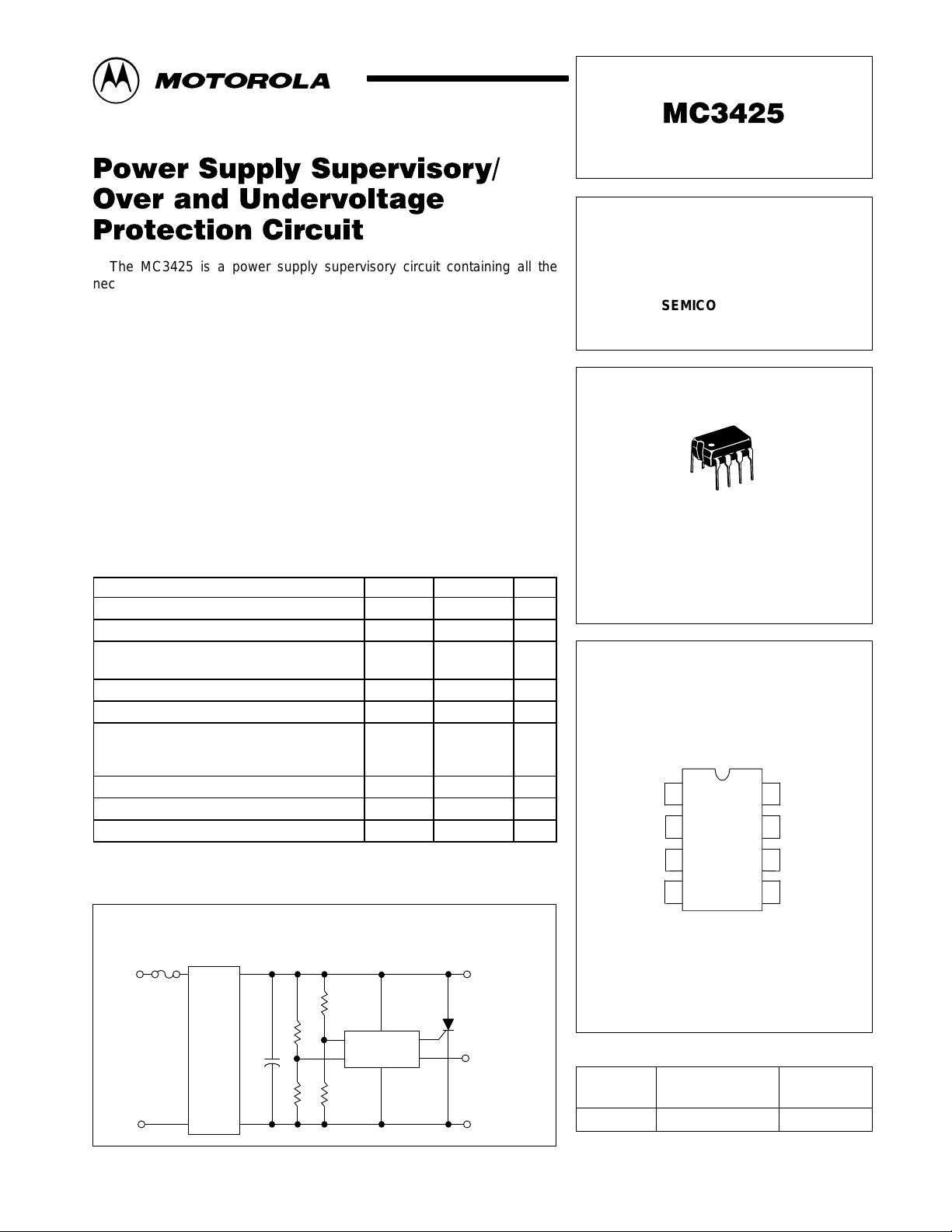
Simplified Application
Overvoltage Crowbar Protection, Undervoltage Indication
V
in
DC
Power
Supply
+
C
out
MOTOROLA ANALOG IC DEVICE DATA
MC3425
V
out
Undervoltage
Indication
U.V. Sense
45
(Top View)
U.V. DLY
ORDERING INFORMATION
Operating
Device
MC3425P1 TA = 0° to +70°C Plastic DIP
Motorola, Inc. 1996 Rev 2
Temperature Range
Package
1
MC3425
ELECTRICAL CHARACTERISTICS
(4.5 V ≤ VCC ≤ 40 V; TA = T
Characteristics Symbol Min Typ Max Unit
REFERENCE SECTION
Sense Trip Voltage (Referenced Voltage)
VCC = 15 V
TA= 25°C
T
to T
low
Line Regulation of V
4.5 V ≤ VCC ≤ 40 V; TJ = 25°C
high
(Note 2)
Sense
Power Supply Voltage Operating Range V
Power Supply Current
VCC = 40 V; TA = 25°C; No Output Loads
O.V. Sense (Pin 3) = 0 V;
U.V. Sense (Pin 4) = V
CC
O.V. Sense (Pin 3) = VCC;
U.V. Sense (Pin 4) = 0 V
INPUT SECTION
Input Bias Current, O.V . and U.V. Sense I
Hysteresis Activation Voltage, U.V. Sense
VCC = 15 V; TA = 25°C;
IH = 10%
IH = 90%
Hysteresis Current, U.V. Sense
VCC = 15 V; TA = 25°C; U.V. Sense (Pin 4) = 2.5 V
Delay Pin Voltage (I
Low State
DLY
= 0 mA)
High State
Delay Pin Source Current
VCC = 15 V; V
DLY
= 0 V
Delay Pin Sink Current
VCC = 15 V; V
DLY
= 2.5V
OUTPUT SECTION
Drive Output Peak Current (TA = 25°C) I
Drive Output Voltage
I
= 100 mA; TA = 25° C
DRV
Drive Output Leakage Current
V
= 0 V
DRV
Drive Output Current Slew Rate (TA = 25°C) di/dt – 2.0 – A/µs
Drive Output VCC Transient Rejection
VCC = 0 V to 15 V at dV/dt = 200 V µs;
O.V. Sense (Pin 3) = 0 V; TA = 25°C
Indicator Output Saturation Voltage
I
= 30 mA; TA = 25°C
IND
Indicator Output Leakage Current
V
OH(IND)
= 40 V
Output Comparator Threshold Voltage (Note 3) V
Propagation Delay Time
(VCC = 15 V; TA = 25°C)
Input to Drive Output or Indicator Output
100 mV Overdrive, C
DLY
= 0 µF
Input to Delay
2.5 V Overdrive (0 V to 5.0 V Step)
NOTES: 2. T
low
3.The V
to T
= 0° to +70°C
high
limits are approximately the V
th(OC)
limits over the applicable temperature range.
Sense
to T
low
V
Reg
I
CC(off)
I
CC(on)
V
V
OL(DLY)
V
OH(DLY)
I
DLY(source)
I
DLY(sink)
DRV(peak)
V
OH(DRV)
I
DRV(leak)
I
DRV(trans)
V
IND(sat)
I
IND(leak)
t
PLH(IN/OUT)
t
PLH(IN//DLY)
[Note 2], unless otherwise noted.)
high
Sense
2.4
2.33
line
CC
– 7.0 15 mV
4.5 – 40 Vdc
– 8.5 10 mA
– 16.5 19 mA
IB
– 1.0 2.0 µA
H(act)
–
–
I
H
9.0 12.5 16 µA
–
VCC–0.5
VCC–0.15
140 200 260 µA
1.8 3.0 – mA
200 300 – mA
VCC–2.5 VCC–2.0 – V
– 15 200 nA
– 1.0 – mA
– 560 800 mV
– 25 200 nA
th(OC)
2.33 2.5 2.63 V
– 1.7 – µs
– 700 – ns
2.5
2.5
0.6
0.8
0.2
2.6
2.63
–
–
0.5
–
(Peak)
Vdc
V
V
2
MOTOROLA ANALOG IC DEVICE DATA
MC3425
Figure 1. Hysteresis Current versus
Hysteresis Activation V oltage
14
12
µ
, HYSTERESIS CURRENT ( A)
H
I
TA = 25°C
10
8.0
6.0
4.0
2.0
0
0 0.2 0.4 0.6 0.8 1.0 1.2 1.4 1.6
VCC = 40 V
V
CC
=15V
V
, HYSTERESIS ACTIVATION VOLTAGE (V)
H(act)
VCC = 5.0 V
Figure 3. Hysteresis Current
versus T emperature
15.0
µ
14.0
U.V. Sense = 2.5 V
Figure 2. Hysteresis Activation V oltage
versus T emperature
1.2
V
= Voltage Level at
H(act)
VCC = 5.0 V
1.0
0.8
VCC = 15 V
0.6
0.4
0.2
, HYSTERESIS ACTIVATION VOLTAGE (V)
H(act)
V
VCC = 40 V
0
–55 –25 0 25 50 75 100 125
TA, AMBIENT TEMPERATURE (
which Hysteresis Current
(IH) is 90% of full value.
°
C)
Figure 4. Sense Trip Voltage Change
versus T emperature
V
* = 2.400 V * = 2.500 V * = 2.600 V
Sense
0
–10
13.0
12.0
11.0
, HYSTERESIS CURRENT ( A)
H
I
10.0
–55 –25 0 25 50 75 100 125
TA, AMBIENT TEMPERATURE (
°
C)
Figure 5. Output Delay Time versus
Delay Capacitance
, OUTPUT DELAY TIME (mS)t
DLY
100
10
1.0
0.1
0.01
VCC = 15 V
°
C
TA = 25
t
DLY
=
2.5 C
200 µA
DLY
–20
–30
–40
, SENSE TRIP VOLTAGE CHANGE (mW)
–50
Sense
V
–55 –25 0 25 50 75 100 125
∆
VCC = 15 V
*V
at TA = 25
Sense
TA, AMBIENT TEMPERATURE (°C)
°
C
Figure 6. Delay Pin Source Current
µ
260
240
220
200
, DELAY PIN SOURCE CURRENT ( A)
180
versus T emperature
VCC = 40 V
VCC = 15 V
VCC = 5.0 V
0.001
0.0001 0.001 0.01 0.1 1.0 10
C
, DELAY PIN CAPACITANCE (µF)
DLY
MOTOROLA ANALOG IC DEVICE DATA
160
DLY(source)
I
–55 –25 0 25 50 75 100 125
°
TA, AMBIENT TEMPERATURE (
C)
3
MC3425
Figure 7. Drive Output Saturation Voltage
versus Output Peak Current
5.0
VCC = 15 V
4.0
1.0% Duty Cycle @ 300 Hz
°
C
TA = 25
3.0
2.0
1.0
, DRIVE OUTPUT SATURATION VOLTAGE (V)
0
0 100 200 300 400
OH(DRV)
V
I
DRV(peak)
, DRIVE OUTPUT PEAK CURRENT (mA)
Figure 9. Drive Output Saturation Voltage
versus T emperature
2.500
VCC = 15 V
2.460
2.420
I
DRV(peak)
1.0% Duty Cycle @ 300 Hz
= 200 mA
Figure 8. Indicator Output Saturation Voltage
versus Output Sink Current
0.4
0.3
0.2
VCC = 15 V
°
C
TA = 25
0.1
0
, INDICAT OR OUTPUT SATURATION VOL TAGE (V)
010203040
I
, INDICAT OR OUTPUT SINK CURRENT (mA)
IND(sat)
V
IND
Figure 10. Power Supply Current
versus V oltage
28
Curve O.V. Sense U.V. Sense
AVCCGnd
24
B Gnd V
20
16
CC
A
2.380
2.340
, DRIVE OUTPUT SATURATION VOTLAGE (V)
2.300
–55 –25 0 25 50 75 100 125
OH(DRV)
V
TA, AMBIENT TEMPERATURE (
°
C)
12
8.0
, POWER SUPPLY CURRENT (mA)
4.0
CC
I
0
0 5.0 10 15 20 25 30 35 40
VCC, POWER SUPPLY VOLTAGE (V)
B
TA = 25°C
4
MOTOROLA ANALOG IC DEVICE DATA

MC3425
APPLICATIONS INFORMATION
Figure 11. Overvoltage Protection and
Undervoltage Fault Indication with
Programmable Delay
R1A R1B
8
+
Power
Supply
4.5V to 40V
–
R2A
U.V. Hysteresis = I
t
= 12500 C
DLY
DLY
4
I
H
3
R2B
C
DLY
R1B R2B
H
R1B + R2B R2A
V
CC
U.V.
Sense
O.V.
Sense
O.V.
DLY
275
MC3425
Gnd
, V
O(trip)
U.V.
IND
O.V.
DRV
U.V.
DLY
U.V. Fault
Indicator
6
1
C
DLY
– 2.5 V
1 +
Gnd
R1A
+V
Figure 12. Overvoltage Protection of 5.0 V
Supply with Line Loss Detector
O
V
in
AC Line
+5.0V
Power
Supply
100
U.V. Sense
Pin 4
U.V. DLY
Pin 5
U.V. IND
Pin 6
8
V
15k
4
31
10k
µ
0.01
CC
U.V.
Sense
O.V.
Sense
O.V.
DLY
275
F
MC3425
Gnd
U.V.
IND
O.V.
DRV
U.V.
DLY
VO = 5.0 V
V
= 6.25 V
O(trip)
1.0k
6
0.33
µ
F
2.5V
2.5V
OFF
ON
Line Loss
Output
Figure 13. Overvoltage Audio Alarm Circuit Figure 14. Programmable Frequency Switch
12V
3
O.V.
Sense
MC3425
U.V.
4
Sense
U.V.
DLY
572
µ
F
0.1
8
V
CC
Gnd
O.V.
DRV
O.V.
DLY
Output Pulse when:
f
(input)
1.0k
2.5V
2.5V
ON
OFF
C
1
DLY
+
12V
Power
Supply
12k
2.7k
82k
6.8k
0.1
3
4
µ
O.V.
Sense
U.V.
Sense
U.V.
DLY
F
8
V
CC
MC3425
O.V.
DLY
275
O.V.
DRV
Gnd
+V
Alarm On when:
VO = 13.6 V
1
Ω
100
Gnd
O
Input Signal
I.V. p–p
5.0
µ
F
10k
10k
O.V. Sense
Pin 3
O.V. DLY
Pin 2
O.V. DRV
Pin 1
<
25000 C
1
DLY
MOTOROLA ANALOG IC DEVICE DATA
5

MC3425
CIRCUIT DESCRIPTION
The MC3425 is a power supply supervisory circuit
containing all the necessary functions required to monitor
over and undervoltage fault conditions. The block diagram
is shown below in Figure 15. The Overvoltage (O.V.) and
Undervoltage (U.V.) Input Comparators are both
referenced to an internal 2.5 V regulator. The U.V. Input
Comparator has a feedback activated 12.5 µA current sink
(IH) which is used for programming the input hysteresis
voltage (VH). The source resistance feeding this input (RH)
determines the amount of hysteresis voltage by VH = IHR
= 12.5 × 10⁻⁶ RH.
Separate Delay pins (O.V . DL Y, U.V. DLY .) are provided for
each channel to independently delay the Drive and Indicator
outputs, thus providing greater input noise immunity . The two
Delay pins are essentially the outputs of the respective input
comparators, and provide a constant current source,
I
DLY(source)
, of typically 200 µA when the noninverting input
voltage is greater than the inverting input level. A capacitor
connected from these Delay pins to ground, will establish a
predictable delay time (t
) for the Drive and Indicator
DLY
outputs. The Delay pins are internally connected to the
noninverting inputs of the O.V . and U.V. Output Comparators,
which are referenced to the internal 2.5 V regulator.
Therefore, delay time (t
) is based on the constant current
DL Y
source, I
(C
DLY
t
DLY
) to 2.5 V.
DLY(source)
V
=
I
DLY(source)
Figure 5 provides C
, charging the external delay capacitor
ref CDLY
2.5 C
DLY
=
200 µA
values for a wide range of time
DLY
= 12500 C
DL Y
delays. The Delay pins are pulled low when the respective
H
input comparator’s noninverting input is less than the
inverting input. The sink current, I
DLY(sink)
, capability of the
Delay pins is ≥ 1.8 mA and is much greater than the typical
200 µA source current, thus enabling a relatively fast delay
capacitor discharge time.
The Overvoltage Drive Output is a current–limited
emitter–follower capable of sourcing 300 mA at a turn–on
slew rate at 2.0 A/µs, ideal for driving “Crowbar” SCR’s. The
Undervoltage Indicator Output is an open–collector, NPN
transistor, capable of sinking 30 mA to provide sufficient drive
for LED’s, small relays or shut–down circuitry. These current
capabilities apply to both channels operating simultaneously ,
providing device power dissipation limits are not exceeded.
The MC3425 has an internal 2.5 V bandgap reference
regulator with an accuracy of ± 4.0% for the basic device.
O.V.
Sense
3
U.V.
Sense
4
12.5µA
Note: All voltages and currents are nominal.
+
Comparator
–
Comparator
I
H
Input Section
+
–
Input
O.V.
Input
U.V.
Figure 15. Representative Block Diagram
V
CC
8
200
+
µ
A
200
+
µ
A
52 7
U.V.
O.V.
DLY
DLY
+
+
Output
Comparator
–
O.V.
–
Output
Comparator
U.V.
+
+
2.5V
Reference
Regulator
Gnd
+
Output Section
O.V.
1
6
DRV
U.V.
IND
6
MOTOROLA ANALOG IC DEVICE DATA

MC3425
CROWBAR SCR CONSIDERATIONS
Referring to Figure 16, it can be seen that the crowbar
SCR, when activated, is subject to a large current surge from
the output capacitance, C
. This capacitance consists of
out
the power supply output capacitors, the load’s decoupling
capacitors, and in the case of Figure 16A, the supply’s input
filter capacitors. This surge current is illustrated in Figure 17,
and can cause SCR failure or degradation by any one of
three mechanisms: di/dt, absolute peak surge, or I2t. The
interrelationship of these failure methods and the breadth of
the applications make specification of the SCR by the
semiconductor manufacturer difficult and expensive.
Therefore, the designer must empirically determine the SCR
and circuit elements which result in reliable and effective OVP
operation. However, an understanding of the factors which
influence the SCR’s di/dt and surge capabilities simplifies
this task.
1. di/dt
As the gate region of the SCR is driven on, its area of
conduction takes a finite amount of time to grow, starting as a
very small region and gradually spreading. Since the anode
Figure 16. Typical Crowbar Circuit Configurations
current flows through this turned–on gate region, very high
current densities can occur in the gate region if high anode
currents appear quickly (di/dt). This can result in immediate
destruction of the SCR or gradual degradation of its forward
blocking voltage capabilities – depending on the severity of
the occasion.
The value of di/dt that an SCR can safely handle is
influenced by its construction and the characteristics of the
gate drive signal. A center–gate–fire SCR has more di/dt
capability than a corner–gate–fire type, and heavily
overdriving ( 3 to 5 times IGT) the SCR gate with a fast < 1.0
µs rise time signal will maximize its di/dt capability. A typical
maximum number in phase control SCRs of less than 50
A(RMS) rating might be 200 A/µs, assuming a gate current of
five times IGT and < 1.0 µs rise time. If having done this, a di/dt
problem is seen to still exist, the designer can also decrease
the di/dt of the current waveform by adding inductance in
series with the SCR, as shown in Figure 18. Of course, this
reduces the circuit’s ability to rapidly reduce the dc bus
voltage and a tradeoff must be made between speedy
voltage reduction and di/dt.
(A) SCR Across Input of Regulator
V
in
(B) SCR Across Output of Regulator
V
in
Series
Regulator
++
C
in
Regulator
++
C
in
*Needed if supply is not current limited.
Series
C
out
C
out
MC3425
*
MC3425
V
out
V
out
MOTOROLA ANALOG IC DEVICE DATA
7

MC3425
Figure 17. Crowbar SCR Surge Current Waveform
l
di
dt
2. Surge Current
If the peak current and/or the duration of the surge is
excessive, immediate destruction due to device overheating
will result. The surge capability of the SCR is directly
proportional to its die area. If the surge current cannot be
reduced (by adding series resistance – see Figure 18) to a
safe level which is consistent with the system’s requirements
for speedy bus voltage reduction, the designer must use a
higher current SCR. This may result in the average current
capability of the SCR exceeding the steady state current
requirements imposed by the DC power supply.
l
pk
Surge Due to
Output Capacitor
Current Limited
Supply Output
t
A WORD ABOUT FUSING
Before leaving the subject of the crowbar SCR, a few
words about fuse protection are in order. Referring back to
Figure 16A, it will be seen that a fuse is necessary if the
power supply to be protected is not output current limited.
This fuse is not meant to prevent SCR failure but rather to
prevent a fire!
In order to protect the SCR, the fuse would have to
possess an I2t rating less than that of the SCR and yet have
a high enough continuous current rating to survive normal
supply output currents. In addition, it must be capable of
successfully clearing the high short circuit currents from the
supply. Such a fuse as this is quite expensive, and may not
even be available.
The usual design compromise then is to use a garden
variety fuse (3AG or 3AB style) which cannot be relied on to
blow before the thyristor does, and trust that if the SCR does
fail, it will fail short circuit. In the majority of the designs, this
will be the case, though this is difficult to guarantee. Of
course, a sufficiently high surge will cause an open. These
comments also apply to the fuse in Figure 16B.
CROWBAR SCR SELECTION GUIDE
As an aid in selecting an SCR for crowbar use, the
following selection guide is presented.
Figure 18. Circuit Elements Affecting
SCR Surge & di/dt
R
LeadLLead
ESR
Output
ESL
R & L EMPIRICALLY DETERMINED!
Cap
To
MC3423
R
L
UNDERVOLTAGE SENSING
An undervoltage sense circuit with hysteresis may be
designed, as shown in Figure 11, using the following
equations:
V
*
12.5mA
2.5 R1
CC1
*
V
CC1
2.5
where: V
R2
+
+
CCU
V
R1
is the designed upper trip point
CCU
(output indicator goes off)
V
is the lower trip point
CC1
(output indicator goes on)
Device I
MCR310 Series 10 A 100 A
MCR16 Series 16 A 150 A
MCR25 Series 25 A 300 A
2N6501 Series 25 A 300 A
MCR69 Series 25 A 750 A
MCR264 Series 40 A 400 A
MCR265 Series 55 A 550 A
RMS
I
TSM
8
MOTOROLA ANALOG IC DEVICE DATA

NOTE 2
–T–
SEATING
PLANE
H
58
–B–
14
F
–A–
C
N
D
K
G
0.13 (0.005) B
M
T
MC3425
OUTLINE DIMENSIONS
P1 SUFFIX
PLASTIC PACKAGE
CASE 626–05
ISSUE K
L
J
M
M
A
M
NOTES:
1. DIMENSION L TO CENTER OF LEAD WHEN
FORMED PARALLEL.
2. PACKAGE CONTOUR OPTIONAL (ROUND OR
SQUARE CORNERS).
3. DIMENSIONING AND TOLERANCING PER ANSI
Y14.5M, 1982.
DIM MIN MAX MIN MAX
A 9.40 10.16 0.370 0.400
B 6.10 6.60 0.240 0.260
C 3.94 4.45 0.155 0.175
D 0.38 0.51 0.015 0.020
F 1.02 1.78 0.040 0.070
G 2.54 BSC 0.100 BSC
H 0.76 1.27 0.030 0.050
J 0.20 0.30 0.008 0.012
K 2.92 3.43 0.115 0.135
L 7.62 BSC 0.300 BSC
M ––– 10 ––– 10
N 0.76 1.01 0.030 0.040
INCHESMILLIMETERS
__
MOTOROLA ANALOG IC DEVICE DATA
9

MC3425
NOTES
10
MOTOROLA ANALOG IC DEVICE DATA

MC3425
NOTES
MOTOROLA ANALOG IC DEVICE DATA
11

MC3425
Motorola reserves the right to make changes without further notice to any products herein. Motorola makes no warranty , representation or guarantee regarding
the suitability of its products for any particular purpose, nor does Motorola assume any liability arising out of the application or use of any product or circuit, and
specifically disclaims any and all liability, including without limitation consequential or incidental damages. “T ypical” parameters which may be provided in Motorola
data sheets and/or specifications can and do vary in different applications and actual performance may vary over time. All operating parameters, including “Typicals”
must be validated for each customer application by customer’s technical experts. Motorola does not convey any license under its patent rights nor the rights of
others. Motorola products are not designed, intended, or authorized for use as components in systems intended for surgical implant into the body, or other
applications intended to support or sustain life, or for any other application in which the failure of the Motorola product could create a situation where personal injury
or death may occur. Should Buyer purchase or use Motorola products for any such unintended or unauthorized application, Buyer shall indemnify and hold Motorola
and its officers, employees, subsidiaries, affiliates, and distributors harmless against all claims, costs, damages, and expenses, and reasonable attorney fees
arising out of, directly or indirectly, any claim of personal injury or death associated with such unintended or unauthorized use, even if such claim alleges that Motorola
was negligent regarding the design or manufacture of the part. Motorola and are registered trademarks of Motorola, Inc. Motorola, Inc. is an Equal
Opportunity/Affirmative Action Employer.
How to reach us:
USA/EUROPE / Locations Not Listed: Motorola Literature Distribution; JAPAN: Nippon Motorola Ltd.; Tatsumi–SPD–JLDC, 6F Seibu–Butsuryu–Center,
P.O. Box 20912; Phoenix, Arizona 85036. 1–800–441–2447 or 602–303–5454 3–14–2 Tatsumi Koto–Ku, Tokyo 135, Japan. 03–81–3521–8315
MFAX: RMF AX0@email.sps.mot.com – TOUCHT ONE 602–244–6609 ASIA/PACIFIC: Motorola Semiconductors H.K. Ltd.; 8B Ta i Ping Industrial Park,
INTERNET: http://Design–NET.com 51 Ting Kok Road, Tai Po, N.T., Hong Kong. 852–26629298
12
◊
MOTOROLA ANALOG IC DEVICE DATA
M3425/D
*MC3425/D*
 Loading...