

Datasheet MC33466H-30LT1, MC33466H-33JT1, MC33466H-33LT1, MC33466H-50JT1, MC33466H-50LT1 Datasheet (Motorola)
T
30° t
80°C
The MC33466 series are micropower switching voltage regulators,
specifically designed for handheld and laptop applications, to provide
regulated output voltages using a minimum of external parts. A wide choice
of output voltages are available. These devices feature a very low quiescent
bias current of 15 µA typical.
The MC33466H–XXJT1 series features a highly accurate voltage
reference, an oscillator, a pulse width modulation (PWM) controller, a driver
transistor (Lx), an error amplifier and feedback resistive divider.
The MC33466H–XXLT1 is identical to the MC33466H–XXJT1, except
that a drive pin (EXT) for an external transistor is provided.
Due to the low bias current specifications, these devices are ideally suited
for battery powered computer, consumer , and industrial equipment where an
extension of useful battery life is desirable.
MC33466 Series Features:
• Low Quiescent Bias Current of 15 µA
• High Output Voltage Accuracy of ±2.5%
Order this document by MC33466/D
FIXED FREQUENCY PWM
MICROPOWER DC–to–DC
CONVERTER
SEMICONDUCTOR
TECHNICAL DATA
TAB
1
H SUFFIX
PLASTIC PACKAGE
CASE 1213
(SOT–89)
• Low Startup Voltage of 0.9 V at 1.0 mA
• Soft–Start = 500 µs
• Surface Mount Package
ORDERING INFORMATION
Output
Device
MC33466H–30JT1 3.0
MC33466H–33JT1 3.3
MC33466H–50JT1 5.0
MC33466H–30LT1 3.0
MC33466H–33LT1 3.3
MC33466H–50LT1 5.0
Other voltages from 2.5 V to 7.5 V , in 0.1 V increments are available. Consult factory for
information.
Voltage
Type
Int.
Switch
Ext.
Switch
Drive
Operating
Temperature Range
°
°
o +
= –
A
Package
(Tape/Reel)
SOT–89
(Tape)
SOT–89
(Tape)
PIN CONNECTIONS
MC33466H–XXJT1
1
Ground
2
Output
Lx
3
(Top View)
MC33466H–XXLT1
1
Ground
2
Output
EXT
3
(Top View)
Tab
(Tab is connected
to Pin 2)
Tab
(Tab is connected
to Pin 2)
This document contains information on a new product. Specifications and information herein
are subject to change without notice.
MOTOROLA ANALOG IC DEVICE DATA
Motorola, Inc. 1997 Rev 1
1
MC33466
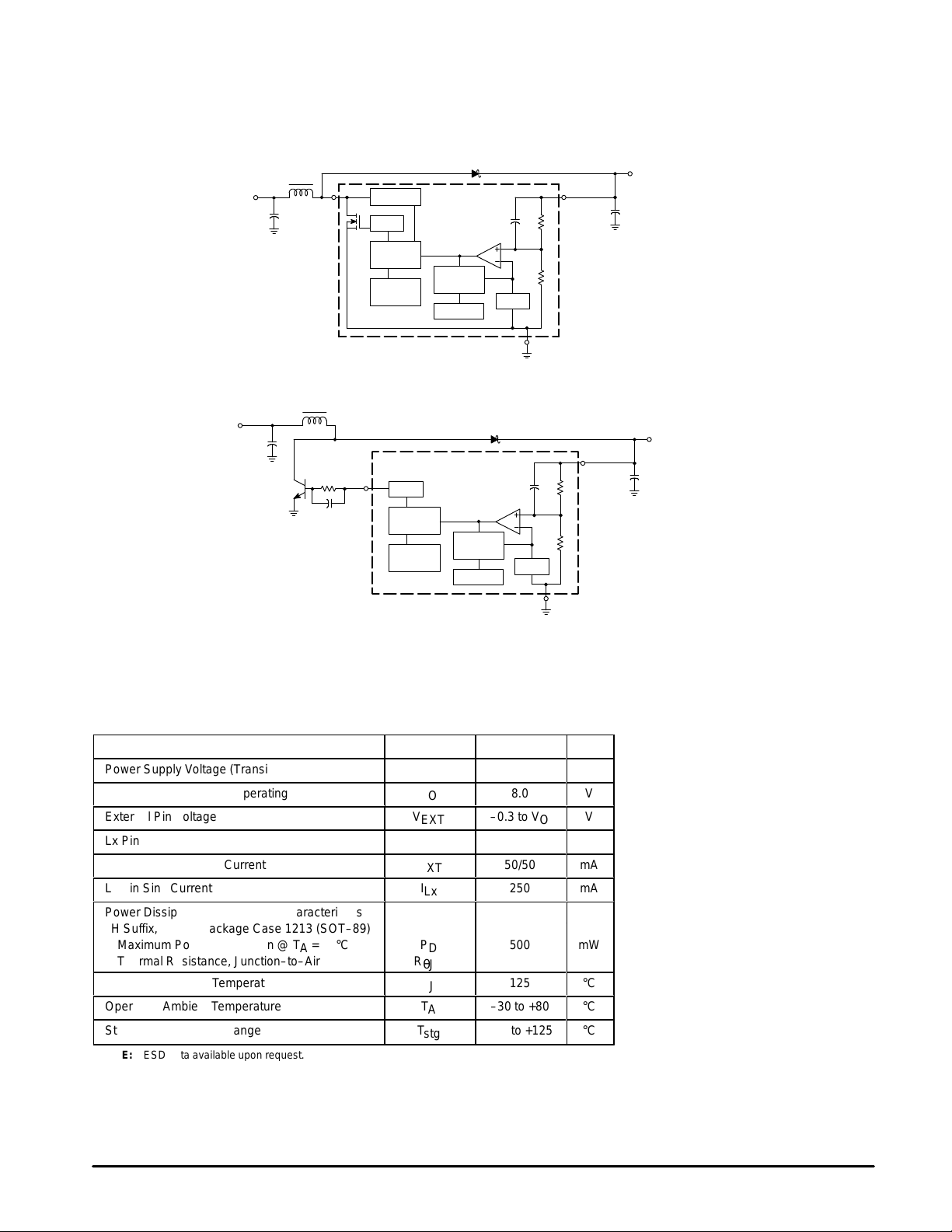
Representative Block Diagrams
MC33466H–XXJT1
Phase
Comp
Soft–Start
D
2
Output
(Voltage
Feedback)
V
ref
Gnd
1
L
V
in
C
in
3
Lx
VLx Limiter
Drive
PWM
Controller
50 kHz
Oscillator
V
O
C
O
L
V
in
C
in
Rb
Q
3
EXT
Cb
This device contains 100 active transistors.
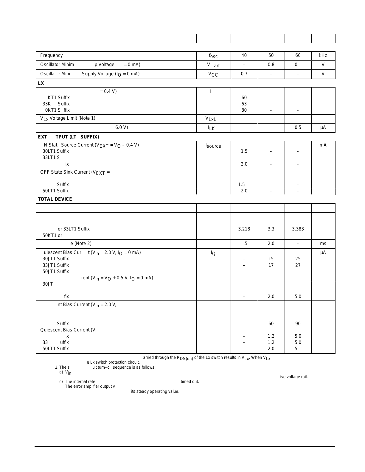
MAXIMUM RATINGS (T
= 25°C, unless otherwise noted.)
C
Rating Symbol Value Unit
Power Supply Voltage (Transient)
Power Supply Voltage (Operating)
External Pin Voltage
Lx Pin Voltage
EXT Pin Source/Sink Current
Lx Pin Sink Current
Power Dissipation and Thermal Characteristics
H Suffix, Plastic Package Case 1213 (SOT–89)
Maximum Power Dissipation @ T
= 25°C P
A
Thermal Resistance, Junction–to–Air R
Operating Junction Temperature
Operating Ambient Temperature
Storage Temperature Range
NOTE: ESD data available upon request.
MC33466H–XXLT1
D
Drive
PWM
Controller
50 kHz
Oscillator
Phase
Comp
Soft–Start
XX Denotes Output Voltage
V
O
V
O
V
V
I
EXT
EXT
Lx
I
Lx
–0.3 to V
D
θJA
T
J
T
A
T
stg
–30 to +80
–40 to +125
V
ref
Gnd
1
12
8.0
O
12
50/50
250
mA
mA
500 mW
200 °C/W
125
2
Output
(Voltage
Feedback)
V
V
V
V
°C
°C
°C
V
O
C
O
2
MOTOROLA ANALOG IC DEVICE DATA
MC33466
ÁÁÁ
ÁÁÁ
ÁÁÁ
ÁÁÁ
ÁÁÁ
ÁÁÁ
ÁÁÁ
ÁÁÁ
ÁÁÁ
ÁÁÁ
ELECTRICAL CHARACTERISTICS (V
Characteristic
= 2.0 V, IO = 10 mA and TA = 25°C, unless otherwise noted.)
CC
Symbol Min Typ Max Unit
OSCILLAT OR
Frequency
Oscillator Minimum Startup Voltage (IO = 0 mA)
Oscillator Minimum Supply Voltage (IO = 0 mA)
V
f
osc
start
V
CC
40
0.7
50
–
0.8
–
60
0.9
–
LX OUTPUT (JT1 SUFFIX)
ON State Sink Current (VLx = 0.4 V)
I
Lx
30KT1 Suffix 60 – –
33KT1 Suffix 63 – –
50KT1 Suffix 80 – –
VLx Voltage Limit (Note 1) V
OFF State Leakage Current (VLx = 6.0 V)
LxLim
I
LKG
0.65 0.8 1.0 V
–
–
0.5
EXT OUTPUT (LT1 SUFFIX)
ON State Source Current (V
= VO – 0.4 V)
EXT
I
source
30LT1 Suffix 1.5 – –
33LT1 Suffix 1.575 – –
50LT1 Suffix 2.0 – –
OFF State Sink Current (V
EXT
= 0.4 V)
I
sink
30LT1 Suffix 1.5 – –
33LT1 Suffix 1.575 – –
50LT1 Suffix 2.0 – –
TOTAL DEVICE
Maximum Duty Ratio Each Cycle D 70 80 90 %
Output Voltage
V
O
30KT1 or 30LT1 Suf fix 2.925 3.0 3.075
33KT1 or 33LT1 Suf fix 3.218 3.3 3.383
50KT1 or 50LT1 Suf fix 4.875 5.0 5.125
Soft–Start Time (Note 2) T
Quiescent Bias Current (Vin = 2.0 V, IO = 0 mA)
ss
I
Q
0.5 2.0 – ms
30JT1 Suffix – 15 25
33JT1 Suffix – 17 27
50JT1 Suffix – 30 45
Quiescent Bias Current (Vin = VO + 0.5 V, IO = 0 mA)
30JT1 Suffix – 1.2 5.0
33JT1 Suffix – 1.2 5.0
50JT1 Suffix – 2.0 5.0
Quiescent Bias Current (Vin = 2.0 V, IO = 0 mA)
I
Q
30LT1 Suffix – 30 50
33LT1 Suffix – 34.5 56
50LT1 Suffix – 60 90
Quiescent Bias Current (Vin = VO + 0.5 V, IO = 0 mA)
30LT1 Suffix – 1.2 5.0
33LT1 Suffix – 1.2 5.0
50LT1 Suffix – 2.0 5.0
NOTES: 1. When the Lx switch is turned on, ILx current carried through the R
turned off by the Lx switch protection circuit.
2.The soft–start circuit turn–on sequence is as follows:
a) Vin is applied.
b) The internal IC V
c) The internal reference steps up to 0.7 V after 200 µs delay has timed out.
d) The error amplifier output voltage integrates down to its steady state value. As the error amplifier output integrates down, the output Lx pin of EXT
pin pulse width gradually widens to its steady operating value.
is held at zero for 200 µs. During this time, the error amplifier output voltage ramps up to the positive voltage rail.
ref
of the Lx switch results in VLx. When VLx reaches V
DS(on)
, the Lx switch is
LxLim
kHz
V
V
mA
µA
mA
mA
V
µA
µA
MOTOROLA ANALOG IC DEVICE DATA
3
MC33466
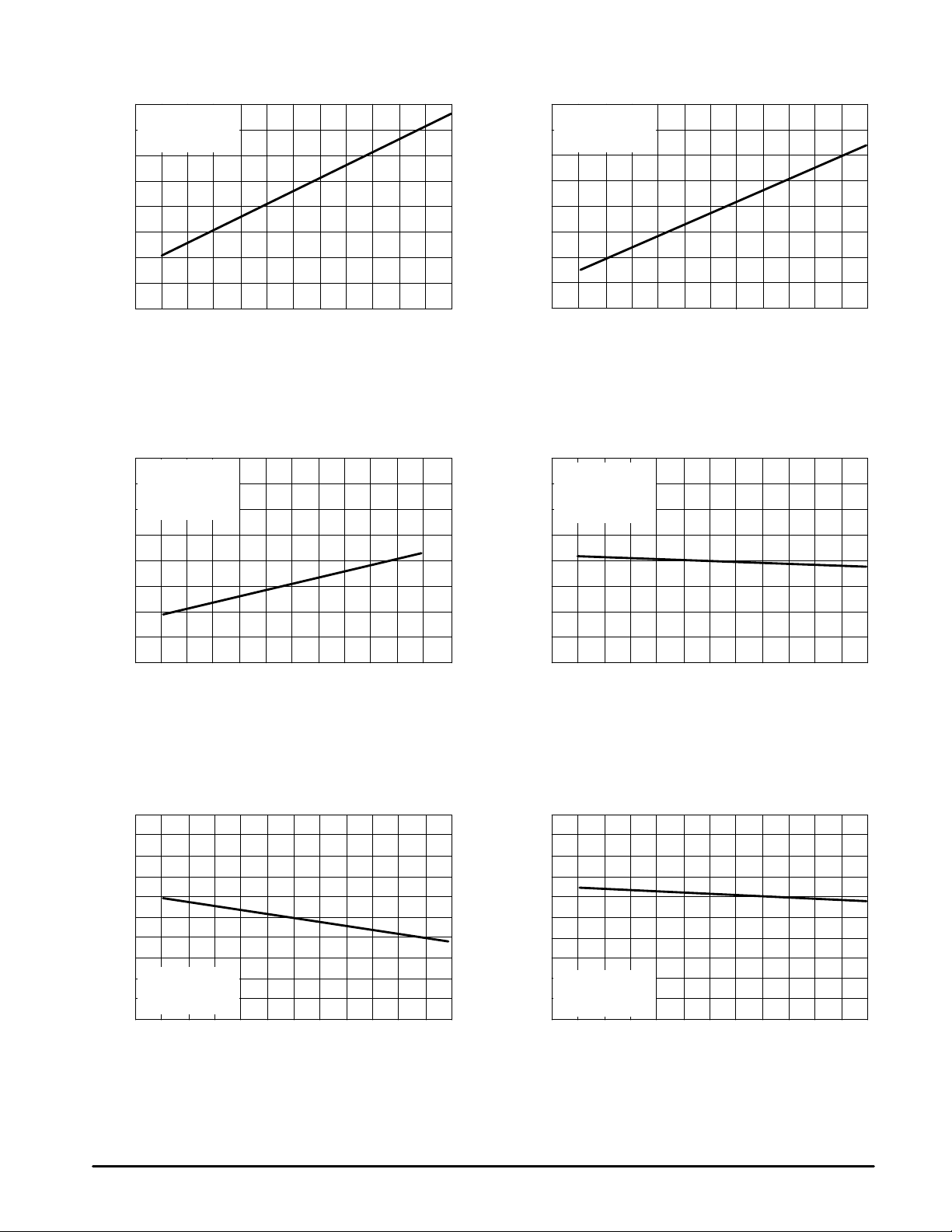
Figure 1. Quiescent Current versus T emperature
50
MC33466H–33JT1
µ
IO = 0 mA
Vin = 2.0 V
40
30
20
, QUIESCENT BIAS CURRENT ( A)
Q
I
10
–40
–20
0
TA, AMBIENT TEMPERATURE (°C)
20 40
60
Figure 3. Oscillator Frequency versus T emperature
100
MC33466H–50JT1
µ
H
L = 120
IO = 10 mA
80
Vin = 3.0 V
Figure 2. Quiescent Current versus T emperature
2.0
MC33466H–33JT1
µ
IO = 0 mA
Vin = 5.5 V
1.6
1.2
0.8
, QUIESCENT BIAS CURRENT ( A)
Q
I
0.4
80 –20
–40
100
MC33466H–50JT1
L = 120
IO = 10 mA
90
Vin = 3.0 V
µ
0
TA, AMBIENT TEMPERATURE (
20
40
°
C)
Figure 4. Maximum Duty Ratio
versus T emperature
H
60
80
, MAXIMUM DUTY RATIO (%)
max
D
80
70
60
–40
–20
0
TA, AMBIENT TEMPERATURE (
20
40
60
°
C)
60
40
, OSCILLAT OR FREQUENCY (kHz)
osc
f
20
–40
–20
0
TA, AMBIENT TEMPERATURE (°C)
20
40
60
80
Figure 5. Lx Switching Current versus Temperature Figure 6. VLx V oltage Limit versus Temperature
200
160
120
80
MC33466H–50JT1
40
, Lx SWITCHING CURRENT (mA)
IO = 10 mA
Lx
I
Vin = 2.0 V
0
–40
–20
0
TA, AMBIENT TEMPERATURE (°C)
20
40
60
80
1.0
0.9
0.8
VOLTAGE LIMIT (V)
0.7
Lx
, V
0.6
MC33466H–50JT1
LxLim
V
IO = 10 mA
Vin = 2.0 V
0.5
–40
–20
0
TA, AMBIENT TEMPERATURE (°C)
20
40
60
80
80
4
MOTOROLA ANALOG IC DEVICE DATA

MC33466
Figure 7. Output Voltage versus Output Current
6.0
5.0
, OUTPUT VOL TAGE (V)
O
V
4.0
3.0
2.0
1.0
Vin = 1.0 V
0
Vin = 2.0 V
20
Vin = 3.0 V
MC33466H–50JT1
L = 120
TA = 25
40
IO, OUTPUT CURRENT (mA)
60
80
Figure 9. Efficiency versus Output Current Figure 10. Efficiency versus Output Current
100
80
60
Vin = 1.0 V
Vin = 1.5 V
Vin = 4.0 V
µ
H
°
C
100
Vin = 2.0 V
120
Figure 8. Output Voltage versus Output Current
6.0
Vin = 2.0 V
5.0
, OUTPUT VOL TAGE (V)
V
O
4.0
3.0
2.0
1.0
100
80
60
0
MC33466H–50LT1
L = 28
TA = 25
µ
Vin = 1.5 V
H
°
C
100
200
IO, OUTPUT CURRENT (mA)
300
400
Vin = 3.0 V
Vin = 4.0 V
500
Vin = 2.0 VVin = 1.5 V
600
EFFICIENCY (%)
, VOLTAGE LIMIT (V)V
hold
/V
start
40
MC33466H–30JT1
µ
H
L = 120
20
0
0
°
C
TA = 25
Figure 17
5.0
10
IO, OUTPUT CURRENT (mA)
15
Figure 11. Startup/Hold Voltage versus
Output Current
2.0
1.6
1.2
V
start
0.8
0.4
0
0
V
hold
2.0
4.0
IO, OUTPUT CURRENT (mA)
6.0
20
8.0
25
MC33466H–50JT1
µ
H
L = 120
°
C
TA = 25
Figure 17
10
30
12
EFFICIENCY (%)
VOLTAGE LIMIT (V)V
Lx
, V
LxLim
40
20
0
0
Vin = 0.9 V
100
200
IO, OUTPUT CURRENT (mA)
300
Figure 12. Startup/Hold V oltage versus
Output Current
1.6
1.4
1.2
V
start
1.0
0.8
V
hold
0.6
0
20
40
IO, OUTPUT CURRENT (mA)
60
MC33466H–30LT1
µ
H
L = 28
°
C
TA = 25
Figure 18
400
80
500
MC33466H–50LT1
µ
H
L = 28
°
C
TA = 25
Figure 18
100
600
120
MOTOROLA ANALOG IC DEVICE DATA
5

Figure 13. Output V oltage versus Temperature
MC33466H–50JT1
5.2
5.1
µ
H
L = 120
IO = 10 mA
Vin = 3.0 V
Figure 17
MC33466
1.0
0.8
Figure 14. Startup/Hold Voltage
versus T emperature
V
start
5.0
4.9
, OUTPUT VOL TAGE (V)
O
V
4.8
–40
TA, AMBIENT TEMPERATURE (°C)
Figure 15. Supply Current versus Input V oltage
µ
, SUPPLY CURRENT ( A)
I
CC
250
200
150
100
50
0
0
Vin, INPUT VOLTAGE (V)
MC33466H–50JT1
L = 120
IO = 10 mA
Figure 17
0.6
V
, STARTUP/HOLD VOLTAGE (V)V
hold
/V
start
0.4
0.2
–40
–20–20 00 2020 4060 806040 80
TA, AMBIENT TEMPERATURE (
MC33466H–50JT1
L = 120
IO = 3.0 mA
Figure 17
°
C)
hold
µ
H
Figure 16. Load Transient Response
MC33466H–50JT1
µ
H
5.4
IO = 1.0 to 30 mA
5.2
5.0
4.8
, OUTPUT VOL TAGE (V)
O
V
4.6
0
µ
H
L = 120
Vin = 3.0 V
Figure 17
101.0 202.0 303.0 405.0 60504.0 6.0
t, TIME (ms)
250
200
150
100
50
0
µ
, OUTPUT CURRENT ( A)
O
I
6
MOTOROLA ANALOG IC DEVICE DATA

MC33466
DEFINITIONS
Quiescent Bias Current – Current which is used to operate
the switching regulator chip and is not delivered to the load.
Leakage Current – Current drawn through a transistor
junction, under a specified collector voltage, when the
transistor is off.
FUNCTIONAL DESCRIPTION
Introduction
The MC33466 series are monolithic power switching
regulators optimized for dc–to–dc converter applications
where power drain must be minimized. The combination of
features in this series allows the system designer to directly
implement step–up, step–down or flyback converters with a
small number of external components. Potential applications
include low power consumer products and battery powered
portable products. Typical application circuits are shown in
Figures 17 through 21.
Operating Description
The MC33466 series converters operate as a fixed
frequency voltage mode regulator. Operation is intended to
be in the discontinuous mode, where the inductor current
ramps up to a peak value which is greater than or equal to
twice the value of the dc input current during the on–time of
the transistor switch. During the off–time of the transistor
switch, the inductor current ramps down to zero and remains
at zero until another switching cycle begins.
Because the output voltage pin is also used as the supply
voltage for powering internal circuitry, an external startup
circuit is needed in step–down converter and flyback designs
to provide initial power to the integrated circuit to begin
switching. The startup circuit needed can be three discrete
components, as shown in Figure 19, or a micropower
undervoltage sensor, as shown in Figure 20.
Oscillator
The oscillator frequency, is internally programmed to
50 kHz. The timing capacitor (CT) discharge to charge ratio
of the oscillator is designed for a maximum duty cycle of 80%
at the Lx or EXT output. During the charge of CT, the
oscillator generates an internal blanking pulse that holds the
PWM control off, disabling the output transistor drive. The
oscillator peak and valley thresholds are 0.5 V and ground,
respectively.
Pulse Width Modulator
The Pulse Width Modulator consists of a comparator with
the oscillator ramp voltage applied to the inverting input,
while the error amplifier output is applied to the noninverting
input. Output switch conduction is initiated when the timing
capacitor is charged to its peak voltage value. When the
timing capacitor ramp discharges to a voltage below the error
amplifier output, the comparator resets a latch terminating
output transistor drive for the duration of the oscillator ramp
period.
Error Amplifier and Reference
An Error Amplifier is provided which has a nominal 80 dB
of voltage gain at dc. Internal compensation components
provide poles at 0.25 Hz, 30 kHz and 33 kHz. Two zeros are
provided at 1.0 kHz and at 2.5 kHz. The output voltage value
is set by the internal voltage divider and a 0.7 V reference
which is trimmed to an accuracy of ±2.5%. Because the loop
compensation components are located within the IC,
discontinuous mode operation is recommended for most
applications.
Driver and Output Switch
To aid in system design flexibility and conversion
efficiency, two output driver options are provided. The
MC33466H–XXJT1 converters have an internal drive
transistor which is capable of sinking currents greater than
60 mA into the Lx pin. An internal VLx limiter circuit senses if
the Lx pin voltage exceeds 1.0 V during ton and turns off the
drive transistor. The MC33466H–XXJT1 provides output
drive for an external transistor.
Applications
The following converter applications show the simplicity
and flexibility of the converter architecture. Three main
converter topologies are demonstrated in Figures 17 through
21.
Figure 17. MC33466H–50KT1 T ypical
Step–Up Application
MBRD520LT1
120 µH
V
in
22 µF
MC33466H–50KT1
3
Lx
Gnd
V
O
1
2
MOTOROLA ANALOG IC DEVICE DATA
22 µF
Figure 18. MC33466H–50L T1 Typical
Step–Up Application
MBRD520LT1
28 µH
V
in
V
O
22 µF
300
MMBT2222ALT1
0.01
MC33466H–50LT1
3
EXT
µ
F
Gnd
V
2
V
O
1
O
5.0 V
100 µF
7

V
in
330
µF
MMBT2907AL T1
1.0 k
MC33466
Figure 19. MC33466H–33JT1 Step–Down Application
Startup Circuit
MMBT2222AL T1
1.5 k
BZX84C3V3L T1
3.3 V
47
µH
MBRD0520LT1
V
O
3.3 V
320 mA
100
3
Lx
Test Condition Results
Line Regulation Vin = 5.0 V to 10 V, IO = 320 mA 7 mV = ±0.1%
Load Regulation Vin = 7.0 V, IO = 3.3 mA to 320 mA 3 mV = ±0.04%
Output Ripple Vin = 7.0 V, IO = 320 mA 70 mVpp
Efficiency Vin = 7.0 V, IO = 320 mA 63.8%
MC33466H–33JT1
VLx Limiter
Drive
PWM
Controller
50 kHz
Oscillator
Phase
Comp
Soft–Start
2
Output
330
µF
V
ref
Gnd
1
330
µF
8
MOTOROLA ANALOG IC DEVICE DATA

V
in
5.0 V
100
µF
MC33466
Figure 20. Micropower Step–Down Application
Startup Circuit
2
In
Out
Gnd
MMBT2907AL T1
1.0 k
MBRD0520LT1
MMBT2222AL T1MC33464N–30ATR
1
10 k3
10 k
µH
47
V
O
3.3 V
300 mA
100
3
Lx
NOTE: Using the MC33464N–30ATR reduces current drawn in the startup circuit to 1 mA during normal operation.
MC33466H–33JT1
VLx Limiter
Drive
PWM
Controller
50 kHz
Oscillator
Phase
Comp
Soft–Start
2
Output
100
V
ref
Gnd
1
µF
MOTOROLA ANALOG IC DEVICE DATA
9

MC33466
Figure 21. Flyback Application
Startup Circuit
1.5 k
MMBT2222AL T1
3.3 V
V
in
100
µF
MMBT2907AL T1
1.0 k
100
Lx
V
O
3.3 V
MC33466H–33KT1
3
VLx Limiter
Drive
PWM
Controller
50 kHz
Oscillator
Phase
Comp
Soft–Start
V
ref
1
Gnd
2
Output
100
µF
10
MOTOROLA ANALOG IC DEVICE DATA

MC33466
Figure 22. Design Equations
Calculation Step–Down Step–Up Flyback
L
t
on
D
I
L(avg)
I
L(pk)
V
ripple(pp)
The following converter design characteristics must be chosen:
Vin – Nominal Operating dc input voltage
VO – Desired dc output voltage
IO – Desired dc output current
V
affect line and load regulation. Capacitor CO should be a low equivalent series resistance (ESR) electrolytic designed for switching regulator
applications.
D – Operating duty cycle = ton(fs). This parameter must be chosen to be <0.5 for step–up and flyback applications.
NOTES: 1. V
2.Iin – DC input switch.
3.fs – Switching frequency, nominally 50 kHz.
4.RO – Load resistance. RO = VO/IO.
5.Ns, Np – In flyback applications Ns is the number of turns of the secondary transformer winding; Np is the number of the primary winding turns.
– Desired peak–to–peak output ripple voltage. For best performance the ripple voltage should be kept to a low value since it will directly
ripple(pp)
– Saturation voltage of the switching transistor.
sat
(Vin–VO)(ton)
t
t
(Vin*
2I
D
fs
(VO)
(Vin)
I
O
VO)(ton)
L
(Vin)(ton)
t
t
ǒ
(VO*
1
8fsC
D
fs
I
O
2I
in
(VO)
in
V
sat
L
Ǔ
Vin)
)(ton)
2
)(ESR
t
ǒ
ƪ
(Vin*
1
2
ȳ
2
)
ȧ
ȴ
O
(Vin*
ȱ
I
ȧ
L(pk)
Ȳ
(Vin)(ton)
t
D
fs
Ns
Ǔ
(Vin))V
Np
I
2I
in
V
O
ƫ
O
in
V
)(ton)
sat
L
Design Example – Step–down Application
Required: Vin = 8.0 V, an output voltage of 3.3 V at 300 mA is desired with an output ripple of less than 300 mVpp.
V
O
+
I
O
3.3
8
+11W
+
0.41.
Choose D = 0.33.
RO+
V
1. Because this is a discontinuous mode design,
2.
3.
4.
5.
Choose CO = two parallel A VX 330 µF tantalum chip capacitors. Part Number TAJE337M006.
Specified maximum ESR for each is 0.9 Ω.
The complete design schematic is shown in Figure 19.
D
ton[
fs
(Vin–VO)(ton)
L
t
Choose L = 47 µH. Coilcraft part number DO3316P–473.
I
+
L(pk)
ESR
t
0.33
+
(50 kHz)
2I
O
(Vin–VO)(ton)
V
ripple(pp)
I
L(pk)
+
+
L
+
6.6 µs.
(8 – 3.3)(6.6 µs)
[2(0.3)]
(8 – 3.3)(6.6 µs)
+
(47 µH)
(300 mV)
(660 mA)
+
0.455W.
+
51.7 µH.
D
t
+
660 mA.
O
V
in
MOTOROLA ANALOG IC DEVICE DATA
11

MC33466
OUTLINE DIMENSIONS
H SUFFIX
PLASTIC PACKAGE
CASE 1213–01
(SOT–89)
ISSUE O
A
E
D
D1
B
A2
C
E1
L1
B
M
0.10 CSBSA
C
B1 2X
e
M
0.10 CSBSA
NOTES:
1. DIMENSIONS ARE IN MILLIMETERS.
2. INTERPRET DIMENSIONS AND TOLERANCING
PER ASME Y14.5M, 1994.
3. DATUM C IS A SEATING PLANE.
MILLIMETERS
DIM MIN MAX
A2 1.40 1.60
B 0.37 0.57
B1 0.32 0.52
C 0.30 0.50
D 4.40 4.60
D1 1.50 1.70
E ––– 4.25
E1 2.40 2.60
e 1.50 BSC
e1 3.00 BSC
L1 0.80 –––
e1
Motorola reserves the right to make changes without further notice to any products herein. Motorola makes no warranty , representation or guarantee regarding
the suitability of its products for any particular purpose, nor does Motorola assume any liability arising out of the application or use of any product or circuit, and
specifically disclaims any and all liability, including without limitation consequential or incidental damages. “T ypical” parameters which may be provided in Motorola
data sheets and/or specifications can and do vary in different applications and actual performance may vary over time. All operating parameters, including “Typicals”
must be validated for each customer application by customer’s technical experts. Motorola does not convey any license under its patent rights nor the rights of
others. Motorola products are not designed, intended, or authorized for use as components in systems intended for surgical implant into the body, or other
applications intended to support or sustain life, or for any other application in which the failure of the Motorola product could create a situation where personal injury
or death may occur. Should Buyer purchase or use Motorola products for any such unintended or unauthorized application, Buyer shall indemnify and hold Motorola
and its officers, employees, subsidiaries, affiliates, and distributors harmless against all claims, costs, damages, and expenses, and reasonable attorney fees
arising out of, directly or indirectly, any claim of personal injury or death associated with such unintended or unauthorized use, even if such claim alleges that
Motorola was negligent regarding the design or manufacture of the part. Motorola and are registered trademarks of Motorola, Inc. Motorola, Inc. is an Equal
Opportunity/Affirmative Action Employer.
How to reach us:
USA/EUROPE/Locations Not Listed: Motorola Literature Distribution; JAPAN: Nippon Motorola Ltd.: SPD, Strategic Planning Office, 4–32–1,
P.O. Box 5405, Denver, Colorado 80217. 303–675–2140 or 1–800–441–2447 Nishi–Gotanda, Shinagawa–ku, Tokyo 141, Japan. 81–3–5487–8488
Mfax: RMFAX0@email.sps.mot.com – TOUCHTONE 602–244–6609 ASIA/ PACIFIC: Motorola Semiconductors H.K. Ltd.; 8B T ai Ping Industrial Park,
INTERNET: http://motorola.com/sps
12
– US & Canada ONLY 1–800–774–1848 51 Ting Kok Road, T a i Po, N.T., Hong Kong. 852–26629298
◊
MOTOROLA ANALOG IC DEVICE DATA
Mfax is a trademark of Motorola, Inc.
MC33466/D
 Loading...