

MOTOROLA MC10E211FN, MC10E211FNR2, MC100E211FNR2 Datasheet
MOTOROLA
SEMICONDUCTOR TECHNICAL DATA
1:6 Differential Clock
Distribution Chip
The MC10E/100E211 is a low skew 1:6 fanout device designed
explicitly for low skew clock distribution applications. The device can be
driven by either a differential or single-ended ECL or, if positive power
supplies are used, PECL input signal (PECL is an acronym for Positive
ECL, PECL levels are ECL levels referenced to +5V rather than ground).
If a single-ended input is to be used the VBB pin should be connected to
the CLK
supply is designed to act as the switching reference for the input of the
E211 under single-ended input conditions, as a result this pin can only
source/sink up to 0.5mA of current.
• Guaranteed Low Skew Specification
• Synchronous Enabling/Disabling
• Multiplexed Clock Inputs
• V
• Internal 75kΩ Input Pulldown Resistors
• Common and Individual Enable/Disable Control
• High Bandwidth Output Transistors
• Extended 100E V
of a lower speed scan or test clock along with the high speed system
clock. When LOW (or left open in which case it will be pulled LOW by the
input pulldown resistor) the SEL pin will select the differential clock input.
input and bypassed to ground via a 0.01µF capacitor. The V
Output for Single-Ended Use
BB
Range of –4.2V to –5.46V
EE
The E21 1 features a multiplexed clock input to allow for the distribution
BB
MC10E211
MC100E211
1:6 DIFFERENTIAL
CLOCK DISTRIBUTION CHIP
FN SUFFIX
PLASTIC PACKAGE
CASE 776-02
Both a common enable and individual output enables are provided. When asserted the positive output will go LOW on the next
negative transition of the CLK (or SCLK) input. The enabling function is synchronous so that the outputs will only be
enabled/disabled when the outputs are already in the LOW state. In this way the problem of runt pulse generation during the
disable operation is avoided. Note that the internal flip flop is clocked on the falling edge of the input clock edge, therefore all
associated specifications are referenced to the negative edge of the CLK input.
The output transitions of the E211 are faster than the standard ECLinPS edge rates. This feature provides a means of
distributing higher frequency signals than capable with the E111 device. Because of these edge rates and the tight skew limits
guaranteed in the specification, there are certain termination guidelines which must be followed. For more details on the
recommended termination schemes please refer to the applications information section of this data sheet.
FUNCTION TABLE
CLK SCLK SEL ENx Q
H/L
X
Z*
* Z = Negative transition of CLK or SCLK
X
H/L
Z*
L
H
X
L
L
H
CLK
SCLK
L
ECLinPS is a trademark of Motorola Inc.
5/95
Motorola, Inc. 1996
2–1
REV 3
MC10E211 MC100E211
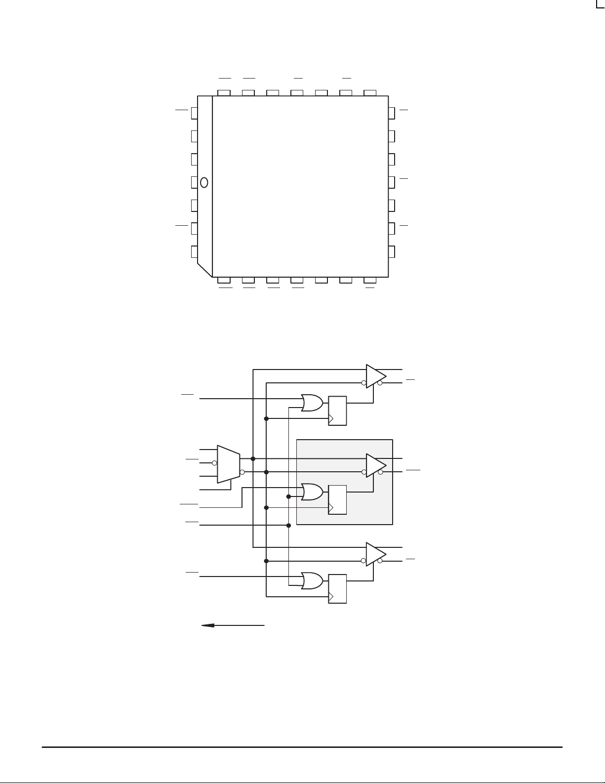
EN3
SEL
SCLK
V
CLK
CLK
V
BB
EE
EN0
EN4 EN5 V
25
26
27
28
1
2
3
4
5
CEN
24
6
EN2
Q5 Q5 Q4 Q4
CC0
22
23
7
8
EN1
EN0
Pinout: 28-Lead PLCC (Top View)
21
CC0
19
20
18
Q3
17
Q3
16
V
CC
Q2
15
14
Q2
Q1
13
12
Q1
11109
Q0
Q0V
Q0
Q0
QD
CLK
CLK
SCLK
SEL
EN1-4
CEN
EN5
V
BB
0
1
BITS 1-4
Q1-4
Q1-4
QD
Q5
Q5
QD
Logic Diagram
MOTOROLA ECLinPS and ECLinPS Lite
2–2
DL140 — Rev 4
MC10E211 MC100E211
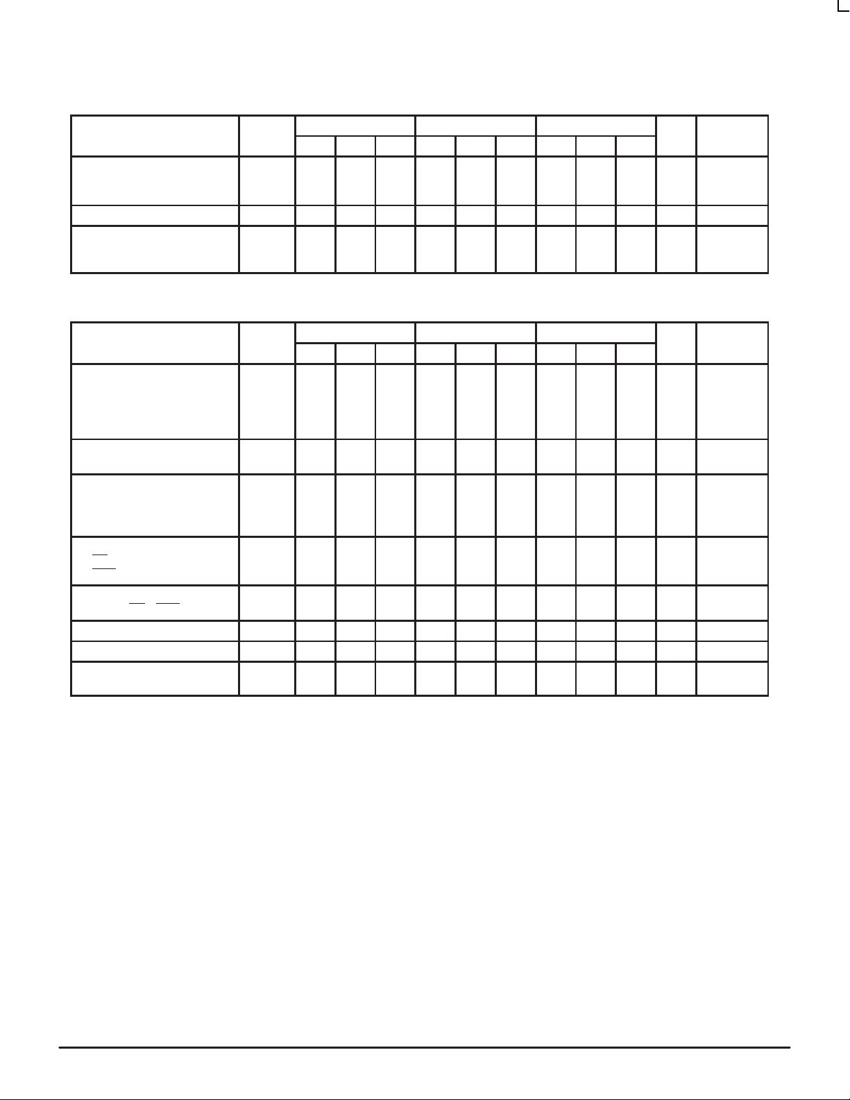
DC CHARACTERISTICS (VEE = VEE(min) to VEE(max); VCC = V
0°C 25°C 85°C
Characteristic Symbol Min Typ Max Min Typ Max Min Typ Max Unit Condition
Output Reference Voltage
10E
100E
Input High Current I
Power Supply Current
10E
100E
AC CHARACTERISTICS (V
Characteristic Symbol Min Typ Max Min Typ Max Min Typ Max Unit Condition
Propagation Delay to Output
CLK to Q (Diff)
CLK to Q (SE)
SCLK to Q
SEL to Q
Disable Time
CLK or SCLK to Q
Part–to–Part Skew
CLK (Diff) to Q
CLK (SE), SCLK to Q
Within-Device Skew
Setup Time
EN
x to CLK
to CLK
CEN
Hold Time
CLK to EN
Minimum Input Swing (CLK) V
Com. Mode Range (CLK) V
Rise/Fall Times
20 – 80%
1. Within-Device skew is defined for identical transitions on similar paths through a device.
2. Setup, Hold and Disable times are all relative to a falling edge on CLK or SCLK.
3. Minimum input swing for which AC parameters are guaranteed. Full DC ECL output swings will be generated with only 50mV input swings.
4. The range in which the high level of the input swing must fall while meeting the VPP spec. The lower end of the range is VEE dependent and
can be calculated as VEE + 2.4V.
x, CEN
V
BB
–1.38
–1.38
IH
I
EE
= VEE(min) to VEE(max); VCC = V
EE
t
PLH
t
PHL
t
PHL
t
skew
t
s
t
h
PP
CMR
t
r
t
f
119
119
0°C 25°C 85°C
795
930
745
930
650
900
745
970
600 800 600 800 600 800
50
200
–100
200
900 600 900 160 900 600
0.25 1.0 0.25 1.0 0.25 1.0 V 3
–0.4 Note –0.4 Note –0.4 Note V 4
150 400 150 400 150 400
0
–1.27
–1.35
–1.26
–1.38
150 150 150 µA
160
160
CCO
1065
1115
1085
1195
805
755
650
755
270
370
75
200
200
= GND)
CCO
119
119
= GND)
940
940
910
980
50
–100
–1.25
–1.31
–1.26
–1.38
160
160
1075
1125
1095
1205
0
825
775
650
775
270
370
75
200
200
119
137
960
960
930
1000
–100
0
–1.19
–1.26
160
164
1095
1145
1115
1225
270
370
75
V
mA
ps
ps
2
ps
1
ps
2
ps
2
ps
DL140 — Rev 4
2–3 MOTOROLAECLinPS and ECLinPS Lite
 Loading...