

Page 1

Level 1 and 2 Service Manual
6809504A59-O
TM
MOTOKRZR
K1
Wireless Telephone
GSM 850/900/1800/1900 MHz GPRS
Page 2

MOTOROLA and the Stylized M Logo are registered in the US Patent & Trademark Office.
All other product or service names are the property of their respective owners.
The Bluetooth trademarks are owned by their proprietor and used by Motorola, Inc. under license.
© Motorola, Inc. 2006.
All rights reserved.
Mobile Devices Business,
Sawgrass International Concourse
789 International Parkway
Room S2C
Sunrise, FL 33325-6220
Page 3

1 and 2
Contents
Level 1 and 2 Service Manual Contents
K1
6809504A59-O
Contents
Introduction . . . . . . . . . . . . . . . . . . . . . . . . . . . . . . . . . . . . . . . . . . . . . . . . . . . . . . . . . . . . . . . . . . . . . . . . . . . . . . . . . 5
Product Identification . . . . . . . . . . . . . . . . . . . . . . . . . . . . . . . . . . . . . . . . . . . . . . . . . . . . . . . . . . . . . . . . . . . 5
Product Names . . . . . . . . . . . . . . . . . . . . . . . . . . . . . . . . . . . . . . . . . . . . . . . . . . . . . . . . . . . . . . . . . . . . . . . . 5
Product Changes . . . . . . . . . . . . . . . . . . . . . . . . . . . . . . . . . . . . . . . . . . . . . . . . . . . . . . . . . . . . . . . . . . . . . . . 5
Regulatory Agency Compliance . . . . . . . . . . . . . . . . . . . . . . . . . . . . . . . . . . . . . . . . . . . . . . . . . . . . . . . . . . . 5
Computer Program Copyrights . . . . . . . . . . . . . . . . . . . . . . . . . . . . . . . . . . . . . . . . . . . . . . . . . . . . . . . . . . . 6
About This Service Manual . . . . . . . . . . . . . . . . . . . . . . . . . . . . . . . . . . . . . . . . . . . . . . . . . . . . . . . . . . . . . . 6
Warranty Service Policy . . . . . . . . . . . . . . . . . . . . . . . . . . . . . . . . . . . . . . . . . . . . . . . . . . . . . . . . . . . . . . . . . 7
Parts Replacement . . . . . . . . . . . . . . . . . . . . . . . . . . . . . . . . . . . . . . . . . . . . . . . . . . . . . . . . . . . . . . . . . . . . . 8
Specifications . . . . . . . . . . . . . . . . . . . . . . . . . . . . . . . . . . . . . . . . . . . . . . . . . . . . . . . . . . . . . . . . . . . . . . . . . . . . . . 9
Product Overview . . . . . . . . . . . . . . . . . . . . . . . . . . . . . . . . . . . . . . . . . . . . . . . . . . . . . . . . . . . . . . . . . . . . . . . . . . . 11
Features . . . . . . . . . . . . . . . . . . . . . . . . . . . . . . . . . . . . . . . . . . . . . . . . . . . . . . . . . . . . . . . . . . . . . . . . . . . . . 11
General Operation . . . . . . . . . . . . . . . . . . . . . . . . . . . . . . . . . . . . . . . . . . . . . . . . . . . . . . . . . . . . . . . . . . . . . . . . . . . 15
Controls, Indicators, and Input / Output (I/O) Connections . . . . . . . . . . . . . . . . . . . . . . . . . . . . . . . . . . . . 15
Alert Settings . . . . . . . . . . . . . . . . . . . . . . . . . . . . . . . . . . . . . . . . . . . . . . . . . . . . . . . . . . . . . . . . . . . . . . . . 17
Battery Function . . . . . . . . . . . . . . . . . . . . . . . . . . . . . . . . . . . . . . . . . . . . . . . . . . . . . . . . . . . . . . . . . . . . . . 17
Operation . . . . . . . . . . . . . . . . . . . . . . . . . . . . . . . . . . . . . . . . . . . . . . . . . . . . . . . . . . . . . . . . . . . . . . . . . . . . 18
Tools and Test Equipment . . . . . . . . . . . . . . . . . . . . . . . . . . . . . . . . . . . . . . . . . . . . . . . . . . . . . . . . . . . . . . . . . . . . 19
Disassembly . . . . . . . . . . . . . . . . . . . . . . . . . . . . . . . . . . . . . . . . . . . . . . . . . . . . . . . . . . . . . . . . . . . . . . . . . . . . . . . . 20
Removing and Replacing the Battery Cover and Battery . . . . . . . . . . . . . . . . . . . . . . . . . . . . . . . . . . . . . 20
Removing and Replacing the Subscriber Identity Module (SIM) . . . . . . . . . . . . . . . . . . . . . . . . . . . . . . . . 22
Removing and Replacing the Trans Flash Memory Module . . . . . . . . . . . . . . . . . . . . . . . . . . . . . . . . . . . 23
Removing and Replacing the Rear Housing . . . . . . . . . . . . . . . . . . . . . . . . . . . . . . . . . . . . . . . . . . . . . . . . 24
Removing and Replacing the Transceiver Board Assembly . . . . . . . . . . . . . . . . . . . . . . . . . . . . . . . . . . . . 26
Removing and Replacing the Keypad . . . . . . . . . . . . . . . . . . . . . . . . . . . . . . . . . . . . . . . . . . . . . . . . . . . . . 28
Removing and Replacing the Antenna . . . . . . . . . . . . . . . . . . . . . . . . . . . . . . . . . . . . . . . . . . . . . . . . . . . . 29
Removing and Replacing the Keypad Mylar . . . . . . . . . . . . . . . . . . . . . . . . . . . . . . . . . . . . . . . . . . . . . . . . 31
Removing and replacing the Acoustic Gasket . . . . . . . . . . . . . . . . . . . . . . . . . . . . . . . . . . . . . . . . . . . . . . . 35
Removing and Replacing the Flip Assembly Cover . . . . . . . . . . . . . . . . . . . . . . . . . . . . . . . . . . . . . . . . . . 38
Removing and Replacing the Camera Assembly . . . . . . . . . . . . . . . . . . . . . . . . . . . . . . . . . . . . . . . . . . . . . 40
Removing and Replacing the Display Module Assembly . . . . . . . . . . . . . . . . . . . . . . . . . . . . . . . . . . . . . . 42
Removing and Replacing the Flip Hinge and Flex Assembly . . . . . . . . . . . . . . . . . . . . . . . . . . . . . . . . . . . 44
Replacing the CLI and Main Display Lens . . . . . . . . . . . . . . . . . . . . . . . . . . . . . . . . . . . . . . . . . . . . . . . . . 51
Subscriber Identity Module (SIM) and Identification . . . . . . . . . . . . . . . . . . . . . . . . . . . . . . . . . . . . . . . . . . . . . . . 54
SIM Card . . . . . . . . . . . . . . . . . . . . . . . . . . . . . . . . . . . . . . . . . . . . . . . . . . . . . . . . . . . . . . . . . . . . . . . . . . . . 54
Personality Transfer . . . . . . . . . . . . . . . . . . . . . . . . . . . . . . . . . . . . . . . . . . . . . . . . . . . . . . . . . . . . . . . . . . . 54
Identification . . . . . . . . . . . . . . . . . . . . . . . . . . . . . . . . . . . . . . . . . . . . . . . . . . . . . . . . . . . . . . . . . . . . . . . . . 54
Troubleshooting . . . . . . . . . . . . . . . . . . . . . . . . . . . . . . . . . . . . . . . . . . . . . . . . . . . . . . . . . . . . . . . . . . . . . . . . . . . . 56
Manual Test Mode . . . . . . . . . . . . . . . . . . . . . . . . . . . . . . . . . . . . . . . . . . . . . . . . . . . . . . . . . . . . . . . . . . . . 56
Manual Test Mode Commands . . . . . . . . . . . . . . . . . . . . . . . . . . . . . . . . . . . . . . . . . . . . . . . . . . . . . . . . . . . 57
Troubleshooting Chart . . . . . . . . . . . . . . . . . . . . . . . . . . . . . . . . . . . . . . . . . . . . . . . . . . . . . . . . . . . . . . . . . 59
Programming: Software Upgrade and Flexing . . . . . . . . . . . . . . . . . . . . . . . . . . . . . . . . . . . . . . . . . . . . . . 61
Part Numbers . . . . . . . . . . . . . . . . . . . . . . . . . . . . . . . . . . . . . . . . . . . . . . . . . . . . . . . . . . . . . . . . . . . . . . . . 61
Exploded View Diagram . . . . . . . . . . . . . . . . . . . . . . . . . . . . . . . . . . . . . . . . . . . . . . . . . . . . . . . . . . . . . . . . 62
Exploded View Parts List . . . . . . . . . . . . . . . . . . . . . . . . . . . . . . . . . . . . . . . . . . . . . . . . . . . . . . . . . . . . . . . 63
Accessories . . . . . . . . . . . . . . . . . . . . . . . . . . . . . . . . . . . . . . . . . . . . . . . . . . . . . . . . . . . . . . . . . . . . . . . . . . . 63
6809504A59-O October 19, 2006 3
Page 4

Contents K1
4 October 19, 2006 6809504A59-O
Page 5

1 and 2
K1
Level 1 and 2 Service Manual Introduction
6809504A59-O
Introduction
Motorola® Inc. maintains a worldwide organization that is dedicated to provide
responsive, full-service customer support. Motorola products are serviced by an
international network of company-operated product-care centers as well as
authorized independent service firms.
Available on a contract basis, Motorola Inc. offers comprehensive maintenance and
installation programs that allow customers to meet requirements for reliable,
continuous communications.
To learn more about the wide range of Motorola service programs, contact your local
Motorola products representative or the nearest Customer Service Manager.
Product Identification
Motorola products are identified by the model number on a label usually located
under the battery. Use the entire model number when inquiring about the product.
Numbers are also assigned to chassis and kits. Use these numbers when requesting
information or ordering replacement parts.
Product Names
Product names are listed on the front cover. Product names are subject to change
without notice. Some product names, as well as some frequency bands, are available
only in certain markets.
Product Changes
When electrical, mechanical or production changes are incorporated into Motorola
products, a revision letter is assigned to the chassis or kit affected, for example;
-A, -B, or -C, and so on.
The chassis or kit number, complete with revision number, is imprinted during
production. The revision letter is an integral part of the chassis or kit number and
is also listed on schematic diagrams and printed-circuit board layouts.
Regulatory Agency Compliance
This device complies with Part 15 of the FCC Rules. Operation is subject to the
following conditions:
• This device may not cause any harmful interference
• This device must accept interference received, including interference that may
cause undesired operation
This class B device also complies with all requirements of the Canadian
Interference-Causing Equipment Regulations (ICES-003).
Cet appareil numérique de la classe B respecte toutes les exigences du Règlement
sur le matériel brouilleur du Canada.
6809504A59-O October 19, 2006 5
Page 6

Introduction K1
Computer Program Copyrights
The Motorola products described in this manual may include Motorola computer
programs stored in semiconductor memories or other media that are copyrighted
with all rights reserved worldwide to Motorola. Laws in the United States and other
countries preserve for Motorola, Inc. certain exclusive rights to the copyrighted
computer programs, including the exclusive right to copy, reproduce, modify,
decompile, disassemble, and reverse-engineer the Motorola computer programs in
any manner or form without Motorola's prior written consent. Furthermore, the
purchase of Motorola products shall not be deemed to grant either directly or by
implication, estoppel, or otherwise, any license or rights under the copyrights,
patents, or patent applications of Motorola, except for a nonexclusive license to use
the Motorola product and the Motorola computer programs with the Motorola
product.
About This Service Manual
Use of this manual assures proper installation, operation, and maintenance of
Motorola products and equipment. It contains all service information required for
the equipment described and is current as of the printing date. Refer questions
about this manual to the nearest Customer Service Manager.
Audience
This manual aids service personnel in testing and repairing K1 telephones. Service
personnel should be familiar with electronic assembly, testing, and troubleshooting
methods, and with the operation and use of associated test equipment.
Scope
This manual provides basic information relating to K1 telephones, and also provides
procedures and processes for repairing the phones at Level 1 and 2 service centers
including:
•Unit swap out
• Repairing of mechanical faults
• Basic modular troubleshooting
• Testing and verification of unit functionality
• Initiate warranty claims and send faulty modules to Level 3 or 4 repair
centers
6 October 19, 2006 6809504A59-O
Page 7

Level 1 and 2 Service Manual Introduction
Conventions
The following special characters and typefaces, are used in this manual to
emphasize certain types of information.
G
E
Warranty Service Policy
The product is sold with the standard 12-month warranty terms and conditions.
Accidental damage, misuse, and extended warranties offered by retailers are not
supported under warranty. Non-warranty repairs are available at agreed fixed
repair prices.
➧
P
Note: Emphasizes additional information pertinent to the subject
matter.
Caution: Emphasizes information about actions which may result in
equipment damage.
Warning: Emphasizes information about actions which may result
in personal injury.
Keys to be pressed are represented graphically. For example, instead of “Press
the End key”, you will see “Press
Information from a screen is shown in text as similar as possible to what
displays on the screen. For example,
Information that you need to type is printed in boldface type.
P
”.
PHONEBOOK
.
Out-of-Box Failure Policy
The standard out-of-box failure criteria applies. Return customer units that fail
very early on after the date of sale to Manufacturing for root cause analysis, to guard
against epidemic criteria. Manufacturing to bear the costs of early life failure.
Product Support
Customer’s original units will be repaired but not refurbished as standard.
Appointed Motorola Service Hubs will perform warranty and non-warranty field
service for level 2 (assemblies) and level 3 (limited PCB component). Motorola High
Tech Centers will perform level-4 (full component) repairs.
Customer Support
Customer support is available through dedicated Call Centers and in-country help
desks. Product Service training is available through the local Motorola Support
Center.
6809504A59-O October 19, 2006 7
Page 8

Introduction K1
Parts Replacement
When ordering replacement parts or equipment, include the Motorola part number
and description used in the service manual.
When the Motorola part number of a component is not known, use the product model
number or other related major assembly along with a description of the related
major assembly and of the component in question.
In the U.S.A., to contact Motorola, Inc. on your TTY, call: 800-793-7834.
Replacement Parts Service Division (RPSD)
Order replacement parts, test equipment, and manuals from RPSD.
U.S.A. Outside U.S.A.
Phone: 800-422-4210 Phone: 847-538-8023
FAX: 800-622-6210 FAX: 847-576-3023
Website: http://businessonline.motorola.com
EMEA
Phone: +49 461 803 1404
Website: http://emeaonline.motorola.com
Asia
Phone: +65 648 62995
Website: http://asiaonline.motorola.com
8 October 19, 2006 6809504A59-O
Page 9

Level 1 and 2 Service Manual Specifications
Specifications
General Function Specification
Frequency Range GSM 850
Frequency Range GSM 900
Frequency Range DCS 1800
Frequency Range PCS 1900
Channel Spacing 200 kHz
Channels 174 EGSM, 374 DCS, 374 PCS, 124 GSM 850 carriers with
Modulation GMSK at BT = 0.3
Transmitter Phase Accuracy 5 Degrees RMS, 20 Degrees peak
Duplex Spacing 45 MHz
Frequency Stability ± 0.10 ppm of the downlink frequency (Rx)
Operating Voltage +3.2V dc to +5.5V dc (battery)
Transmit Current Drain 101-260 mA average talk current drain
Stand-by Current drain 5 mA (DRX2), 2 mA (DXR9) typical
Temperature Range -10° C to +55° C (+15° F to +130° F)
Dimensions, with 750 mAh Li Ion
battery
Size (Volume) 63 cc (3.96 in
Weight 90 grams (3.17 oz), with battery
Battery Life, with standard 750 mAh
Li-Ion Battery
824-848 MHz Tx
869-893 MHz Rx
880-915 MHz Tx (with EGSM)
925-960 MHZ Rx
1710-1785 MHz Tx
1805-1880 MHz Rx
1850-1910 MHz Tx
1930-1990 MHz Rx
8 channels per carrier
+4.8V dc to +6.5V dc (external connector)
42 mm x 103 mm x 16 mm
(2.08 inches x 3.85 inches x 0.54 inches)
Talk Time 200 - 400 minutes
Standby time 200 -300 hours
3
), with battery
All talk and standby times are approximate and depend on
network configuration, signal strength, and features selected.
Standby times are quoted as a range from DRX=2 to DRX=9.
Talk times are quoted as a range from DTX off to DTX on.
Battery Charge Time 4 hours to 90% of 750 mAh capacity
Alert volume Max 95 dB @5cm, 0.5 Watts input
Transmitter Function Specification
RF Power Output 32 dBm nominal GSM 850/900,
Output Impedance 50 ohms nominal
Spurious Emissions -36 dBm from 0.1 to 1 GHz, -30 dBm from 1 to 4 GHz
Receiver Function Specification
Receive Sensitivity Better than -103 dBm
RX Bit Error Rate (100k bits) Type II < 2%
Speech Coding Function Specification
Speech Coding Type Regular pulse excitation/linear predictive coding with long term
Bit Rate 13.0 kbps
29 dBm nominal GSM 1800/1900
prediction (RPE LPC with LTP)
6809504A59-O October 19, 2006 9
Page 10

Specifications K1
Speech Coding Function Specification
Frame Duration 20 ms
Block Length 260 bits
Classes Class 1 bits = 182 bits; Class 2 bits = 78 bits
Bit Rate with FEC Encoding 22.8 kbps
10 October 19, 2006 6809504A59-O
Page 11

Level 1 and 2 Service Manual Product Overview
Product Overview
Motorola K1 telephones represent the thinnest and slenderest system for mobile
communications (GSM) general packet radio service (GPRS) wireless application
protocol (WAP)-enabled mobile phones. The K1 phones incorporate a new user
interface (UI) for easier operation, allow short message service (SMS) text
messaging, and include personal information manager (PIM) functionality.
The K1 is a quad-band phone that allows roaming within the GSM 900 MHz, GSM
850 MHz, 1800 MHz digital cellular system (DCS), and 1900 MHz PCS bands.
K1 telephones support EDGE, GPRS and SMS in addition to traditional circuit
switched transport technologies.
K1 telephones have a clam form factor. They feature an anodized aluminum housing
and have an externally viewable 96x80 1.0” 65K CSTN external display for caller
identification and date/time, an internal 176x220 1.9” 262K TFT display, and the
speaker located in the flip. The bottom part of the clam (front housing) contains the
keypad, transceiver printed circuit board (PCB), microphone, flex connection,
external accessory connector, smart button, volume buttons, and voice button. The
standard 750 mAh Lithium Ion (Li Ion) battery fits behind a removable back cover.
The phone accepts both 3V and 1.8V mini subscriber identity module (SIM) cards
which fit into the SIM holder next to the battery. The antenna is internal.
Inexpensive direct connection to a computer or handheld device via USB or
Bluetooth™ for data and fax calls, and for synchronizing phonebook entries with
Mobile Phone Tools software, can be accomplished by using the optional data cable
and soft modem.
Features
K1 telephones use advanced, self-contained, sealed, custom integrated circuits to
perform the complex functions required for GSM GPRS communication. Aside from
the space and weight advantage, microcircuits enhance basic reliability, simplify
maintenance, and provide a wide variety of operational functions.
Features available in this family of telephones include:
• Ultra Slim form factor
• EDGE for high speed data access (class 12)
• Video Capture & Playback MPEG4 (15 fps CIF)
• Audio/Video streaming (3GPP)
• Video Progressive Download
• Dedicated Carrier Key
• Integrated Stereo Bluetooth Connectivity (Class 2)
• 2MP digital camera with 8x digital zoom
• MicroSD slot for upgradeable memory
• Push To Share (images, video, audio files)
• Dynamic Idle
• 22MB of embedded end user memory
• Rich, pre-loaded J2ME™ games, screen savers
• Downloadable themes, ringer tones, images, animations
• Image borders, text overlay, image editing
• Midi, MP3, AAC, AAC+ Enhanced, iTunes music player
• PIM functionality with Picture Caller ID
• Voice memo & enhanced predictive text
6809504A59-O October 19, 2006 11
Page 12

Product Overview K1
• Enhanced voice recognition
• Record up to 25 minutes of video on embedded memory
• Firmware Over-The Air (FOTA)
• UI Skinning
• Motosync – contacts (calendar, emails TBC)
12 October 19, 2006 6809504A59-O
Page 13

Level 1 and 2 Service Manual Product Overview
Speaker Dependent Voice Activation and Voice Note Recording
Voice tags can be used for voice dialing up to 20 phone numbers in the phone book
and for creating up to 5 voice shortcuts for menu items. The phone must be “trained”
by the voice tag being read into the phone’s memory twice before it is recognized.
You can add voice tags to the phone’s memory using the usual name addition
methods (i.e., via the phone book menu structure or with the shortcut editor).
➧
➧
➧
You cannot place or receive calls while adding voice tags to the phone’s memory.
Because the GSM standard does not provide the option to store voice tags onto the
SIM card, voice tags are added to the phone’s memory.
K1 telephones also include a voice recorder that allows up to 2 minutes of personal
messages to be recorded. This feature has a complete set of record, playback, and
management tools that make it easy to store and maintain a list of personal memos.
Wireless Access Protocol (WAP) 2.0 Compliancy
In the WAP environment, access to the Internet is initiated in wireless markup
language (WML), which is derived from hypertext markup language (HTML). The
request is passed to a WAP gateway which retrieves the information from the server
in standard HTML (subsequently filtered to WML) or directly in WML if available.
The information is then passed to the mobile subscriber via the mobile network.
The K1 microbrowser can be configured for baud, idle timeout, line type, phone
number, and connection type.
Bitmap image data will download as text. If the image is larger than the screen,
only part of the image will display.
➧
When the user receives a call while in browser mode, the browser will pause and
allow the user to resume after completing the call.
SIM Application ToolkitTM - Class 2
SIM Application Toolkit is a value-added service delivery mechanism that allows
GSM operators to customize the services they offer their customers, from the
occasional user who requests sports news and traffic alerts, to a high call time
business user who receives stock alerts and checks flight times. Operators can now
create their own value-added services menu quickly and easily in the phone. The
customized menu will appear as the first menu and may be updated over-the-air
with new services when customers request them.
6809504A59-O October 19, 2006 13
Page 14

Product Overview K1
Simplified Text Entry
There are three different ways to enter text using the phone keypad:
• iTAP™ predictive text entry. Press a key to generate a character and a
dynamic dictionary uses this to build and display a set of word or name
options. The iTAP™ feature may not be available on the phone in all languages.
• Tap. Press a key to generate a character.
• Numeric. The keypad produces numeric characters only. For some text areas
this is the only method available; for example, phone numbers.
Caller Line Identification
Upon receipt of a call, the calling party’s phone number is compared to the phone
book. If the number matches a phone book entry, that name will be displayed. If
there is no phone book entry, the incoming phone number will be displayed. In the
event that no caller identification information is available, the Incoming Call
message is displayed.
➧
User must subscribe to a caller line identification service through their service
provider.
Other Features
Detailed descriptions of these and other K1 features can be found in the appropriate
user’s guide listed in the “Related Publications” section toward the end of this
manual.
14 October 19, 2006 6809504A59-O
Page 15
Level 1 and 2 Service Manual General Operation
p
General Operation
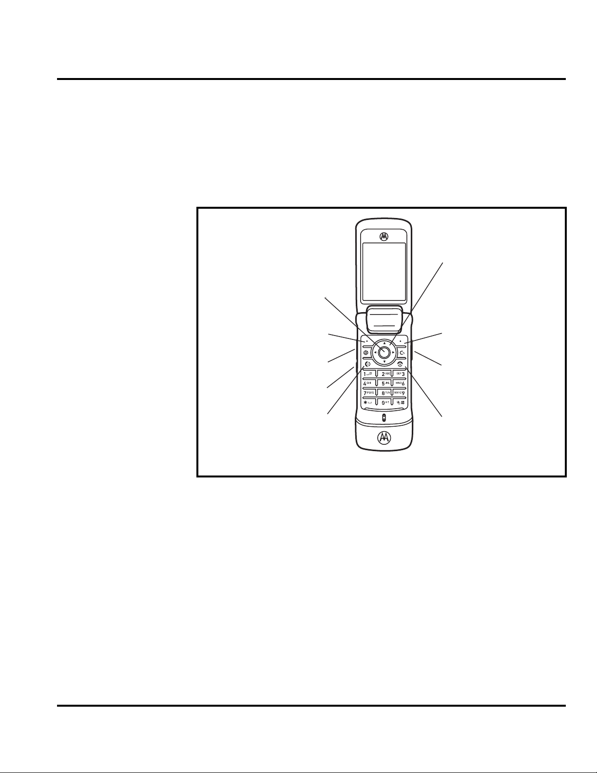
Controls, Indicators, and Input / Output (I/O) Connections
The K1 series telephone’s controls are located on the sides of the flip and on the
keypad. Indicators, in the form of icons, are displayed on the LCD (see Figure 2).
K1 phones have an audible alert transducer on the top and I/O connectors,
consisting of a charger/accessory port, located on the side of the phone. See Figure 1.
Navigate menus.
Open menus.
Left Soft Key
Volume Keys
Select menu items.
Right Soft Key
Voice dial.
PTT/Smart Key
Make & answer calls.
Go handsfree.
Figure 1. Controls, indicators, and I/O
“Soft keys” refer to non-labeled keys that correspond to text options displayed on
the screen. The left and right soft keys perform the function shown in the corners
of the display. The right key will usually select an option whereas the left key will
usually exit a function or return to a previous screen.
The center select key opens the initial menu structure, or allows access to a
submenu.
Turn on & off, hang u
Charge up.
060580o
Color Display
The K1 wireless phones feature a 64k color Thin Film Transistor (TFT) 176x220
pixel display.
6809504A59-O October 19, 2006 15
Page 16
General Operation K1
Display animation makes the phone’s menus move smoothly as the user scrolls up
and down.
Turn animation off to conserve the battery.
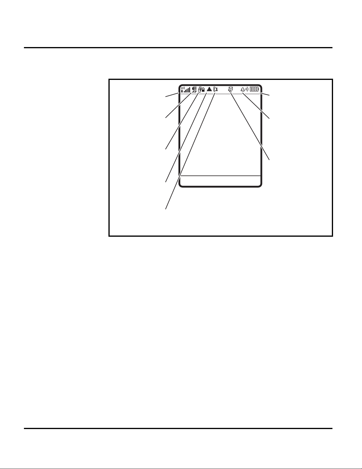
1. Signal
Strength
Service Provider
2. EDGE /
GPRS
3. Data
12:00
Options Main Menu
4. Roam
5. Active Line
Figure 2. Icon Indicators
8. Battery
Level
7. Ring Style
6. Message
060888o
➧
Whether a phone displays all indicators depends on the programming and services
to which the user subscribes.
Figure 2 shows some common icons displayed on the LCD.
1. Data Indicator — Shows connection and data transmission status. The
Bluetooth™ wireless connection indicator
connection is active. Other indicators can include:
4 = secure packet data transfer
7 = unsecure packet data transfer
3 = secure application connection
6 = unsecure application connection
2 = secure Circuit Switch Data (CSD) call
5 = unsecure CSD
2. EDGE/GPRS Indicator — Shows that your phone is using a high-speed
General Packet Radio Service (GPRS) network connection. GPRS allows faster
data transfer speeds. Other indicators can include:
* = GPRS PDP context active
, = GPRS packet data available
3. Signal Strength Indicator — Vertical bars show the strength of the network
connection. You cannot make or receive calls when ! or ) displays.
call
E
shows when a Bluetooth
16 October 19, 2006 6809504A59-O
Page 17

Level 1 and 2 Service Manual General Operation
4. Roam Indicator — The roam indicator shows when your phone is seeking or
using another network outside your home network.
5. Active Line Indicator — Shows ? to indicate an active call, or > to indicate
that call forwarding is on. Indicators for dual-line-enabled SIM cards can include:
* = GPRS PDP context active
, = GPRS packet data available
@ = line 1 active B = line 2 active
A = line 1 active, call forward on
C = line 2 active, call forward on
6. Messaging Presence Indicator — Shows when instant messaging is active.
Indicators can include:
P = IM active I = available for IM
_ = busy Q = invisible to IM
J = available for phone calls
X = offline
When a Java™ application is active, the Java midlet indicator ` displays in this
location.
7. Message Indicator — Displays when you receive a new message. Indicators
can include:
r = text message
t = voicemail message
s = voicemail and text message
d = IM message
a = active chat session
8. Battery Level Indicator — Vertical bars show the battery charge level.
Recharge the battery when Low Battery displays and the battery alert sounds.
9. 9. Ring Style Indicator — Shows the ring style setting.
y = loud ring z = soft ring
| = vibrate } = vibrate then ring
† = vibrate & ring { = silent
Alert Settings
K1 telephones include up to 32 preset alert tones and vibrations that can be applied
to all alert events at the same time.
➧
Pressing any volume key mutes the alert.
Battery Function
Battery Gauge
The telephone displays a battery level indicator icon in the idle screen to indicate
the battery charge level. The gauge shows four levels: 100%, 66%, 33%, and Low
Battery.
6809504A59-O October 19, 2006 17
Page 18

General Operation K1
Battery Removal
Removing the battery causes the device to immediately shut down and any pending
work (for example, partially entered phone book entries or outgoing messages) is
lost.
Operation
G
If the battery is removed while receiving a message, the message will be lost.
For detailed operating instructions, refer to the appropriate User’s Guide listed in
the Related Publications section toward the end of this manual.
18 October 19, 2006 6809504A59-O
Page 19

1 and 2
Level 1 and 2 Service Manual Tools and Test Equipment
K1
6809504A59-O
Tools and Test Equipment
The following table lists tools and test equipment recommended for disassembly
and reassembly of K1 telephones. Use either the listed items or equivalents.
Table 1. General Test Equipment and Tools
Part Number
RSX4043-A Torque Driver Used to remove and replace screws
1
Description Application
—
See Table 7 Rapid Charger
0180386A82
6680388B67
6680388B01 Tweezers, plastic Used during assembly/disassembly
— Digital Multimeter, HP34401A
19501980
0-00-00-40853
0-00-00-40852
8102430Z04 GSM / DCS Test SIM Used to enable manual test mode
1. To order in North America, contact Motorola Aftermarket and Accessories Division (AAD) at (800) 422-4210 or
FAX (800) 622-6210; Internationally, AAD can be reached by calling (847) 538-8023 or faxing (847) 576-3023.
2. Not available from Motorola. To order, contact Hewlett Packard at (800) 452-4844.
3. Available at the AMS Online-shop 62.214.1.200 (for access, please contact your local Motorola parts representative)
3
3
3
Torque Driver Bit T-5 Plus, Apex 440-6IP
Torx Plus or equivalent
Antistatic Mat Kit (includes 66-80387A95
antistatic mat, 66-80334B36 ground
cord, and 42-80385A59 wrist band)
Disassembly tool, plastic with flat and
pointed ends (manual opening tool)
Tweezers, metal Used during assembly/disassembly
2
Generic Press Fixture Must be used to install keypad mylar
K1 Lens- and Trim Ring Press Tool Must be used to install lens and trim ring
K1 and Acoustic Gasket Alignment- and
Press Too
Used with torque driver
Used to charge battery and to power
device
Provides protection from damage to
device caused by electrostatic discharge
(ESD)
Used during assembly/disassembly of
device
Used to measure battery voltage
Must be used to install Acoustic Gasket
6809504A59-O October 19, 2006 19
Page 20
Disassembly K1
Disassembly
The procedures in this section provide instructions for the disassembly of K1
telephones. Tools and equipment used for the phone are listed in Table 1, preceding.
Many of the integrated devices used in this equipment are vulnerable to damage
G
G
Removing and Replacing the Battery Cover and Battery
E
from electrostatic discharge (ESD). Ensure adequate static protection is in place
when handling, shipping, and servicing the internal components of this equipment.
Avoid stressing the plastic in any way to avoid damage to either the plastic or
internal components.
All batteries can cause property damage and/or bodily injury, such as burns if a
conductive material, such as jewelry, keys, or beaded chains touch exposed terminals. The conductive material may complete an electrical circuit (short circuit) and
become quite hot. Exercise care in handling any charged battery, particularly when
placing it inside a pocket, purse, or other container with metal objects.
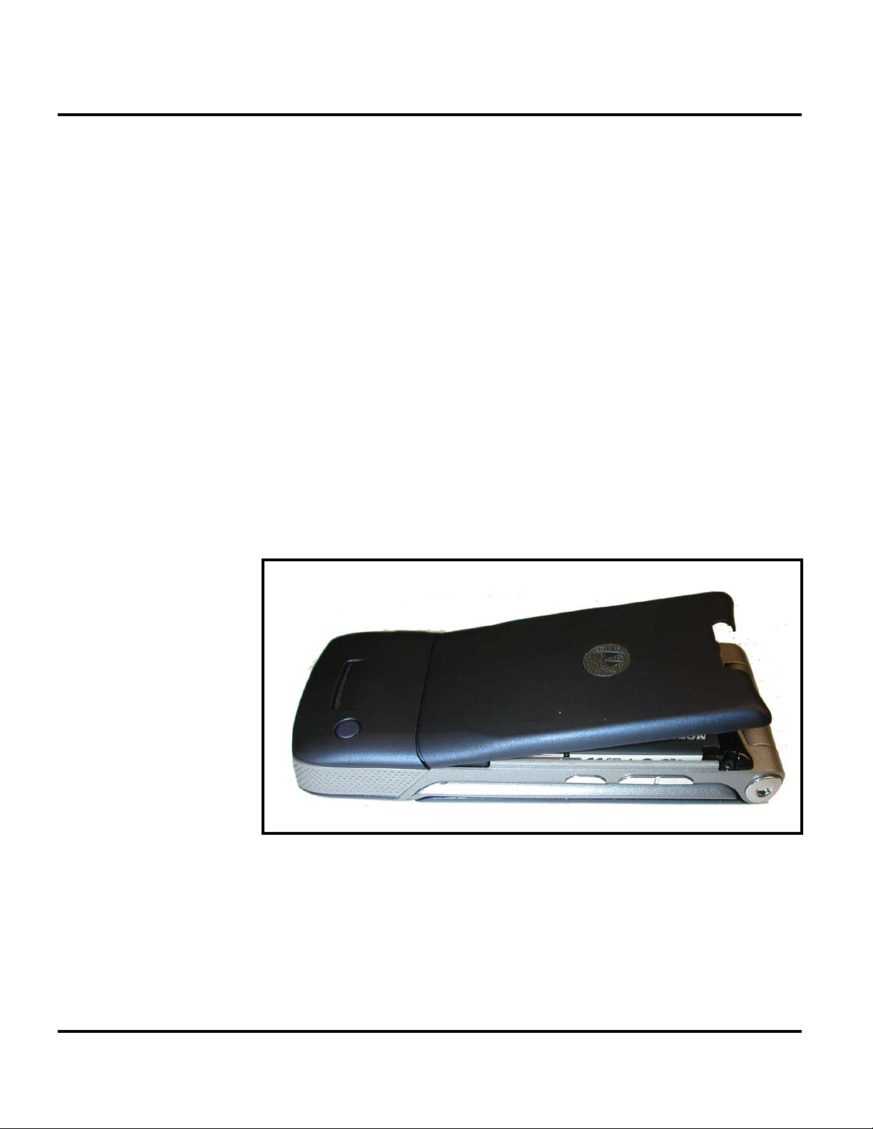
1. Ensure the phone is turned off.
2. Press in and hold the battery door latch, as shown in Figure 1.
Figure 1. Removing the Battery Cover
3. Rotate the battery cover upward and lift it completely off the phone.
061258o
20 October 19, 2006 6809504A59-O
Page 21
Level 1 and 2 Service Manual Disassembly
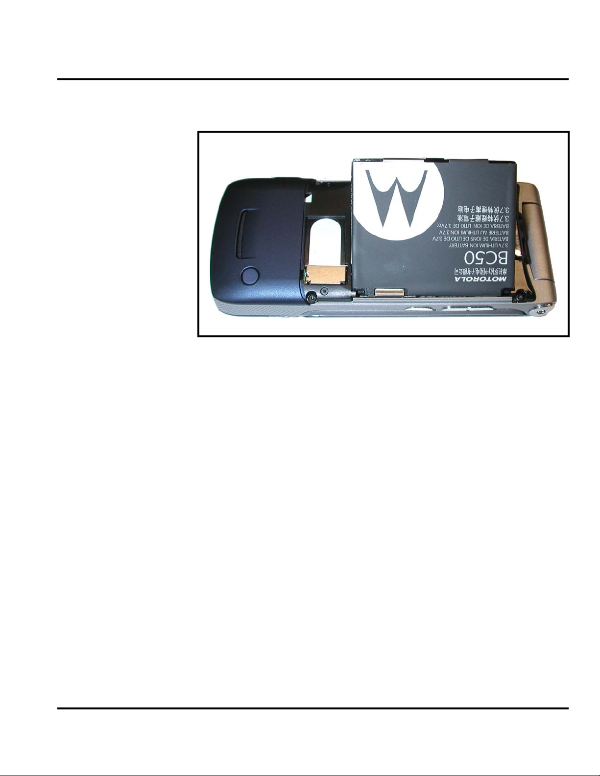
4. Lift the edge of the battery first, then lift the battery from the phone. See
Figure 2.
E
061259o
Figure 2. Removing the battery
There is a danger of explosion if the Lithium Ion battery is replaced incorrectly.
Replace only with the same type of battery or equivalent as recommended by the
battery manufacturer. Dispose of used batteries according to the manufacturer’s
instructions.
5. To replace, align the battery with the battery compartment so the contacts on
the battery match the battery contacts in the phone.
6. Insert the battery, contacts side first, into the battery compartment followed
by the opposite edge of the battery.
7. Insert the bottom edge of the of the battery cover into the rear housing, then
push the top edge of the cover down and snap it into place.
6809504A59-O October 19, 2006 21
Page 22

Disassembly K1
Removing and Replacing the Subscriber Identity Module (SIM)
1. Remove the battery cover and battery as described in the procedures.
SIM
061260o
Figure 3. Removing the SIM
2. Slide the SIM card toward the phone’s battery compartment, as shown in
Figure 3.
3. Carefully lift the SIM from the phone.
4. To replace, insert the SIM into the holder, ensuring the keyed corner of the
SIM faces the outward edge of the phone (see Figure 4).
SIM
061261o
Figure 4. Inserting the SIM
5. Replace the battery and battery cover as described in the procedures.
22 October 19, 2006 6809504A59-O
Page 23

Level 1 and 2 Service Manual Disassembly
Removing and Replacing the Trans Flash Memory Module
1. Remove the battery cover and battery, as described in the procedures.
2. Slide the Trans Flash memory module out of its socket to release, as shown in
Figure 5.
Memory module
061491o
Figure 5. Removing the Trans Flash Memory Module
3. Use the plastic tweezers to carefully lift the memory module out of the phone.
4. To replace, align the memory module according to the diagram in the phone.
5. Place the memory module into it’s slot with the contacts facing down.
6. Slide the memory module all the way into position, as shown in Figure 5.
7. Reinstall the battery, and battery cover as described in the procedures.
6809504A59-O October 19, 2006 23
Page 24

Disassembly K1
Removing and Replacing the Rear Housing
This product contains static-sensitive devices. Use anti-static handling procedures
G
G
to prevent electrostatic discharge (ESD) and component damage.
1. Remove the battery cover, battery, and SIM as described in the procedures.
In addition to 2 screws, the rear housing assembly is fastened with plastic latches.
These are fragile and should be released with care.
2. Using a Torx driver with a T-5 bit, remove the screws at each side of the phone.
Retain the screws for reassembly. See Figure 6.
Housing screws
Housing screws
061264o
Figure 6. Removing the Rear Housing Screws
24 October 19, 2006 6809504A59-O
Page 25

Level 1 and 2 Service Manual Disassembly
3. Release the four housing latches by inserting the pointed end of the plastic
disassembly tool into the openings on the rear housing.
061265o
Figure 7. Removing the Rear Housing Latches
4. Carefully rotate the rear housing away from the front housing and flip
assembly.
5. Lift the rear housing assembly away from the phone.
6. To replace, align the housing latches with the corresponding openings on the
front housing. Gently press the housings together until the catches snap into
place.
7. Replace the 2 housing screws and tighten to a final torque setting of 16 Ncm
(1.5 inch pounds). Do not over tighten.
8. Replace the SIM, battery, and battery cover as described in the procedures.
6809504A59-O October 19, 2006 25
Page 26

Disassembly K1
Removing and Replacing the Transceiver Board Assembly
This product contains static-sensitive devices. Use anti-static handling procedures
G
to prevent electrostatic discharge (ESD) and component damage.
1. Remove the battery cover, battery, SIM, antenna, rear housing and battery
tray as described in the procedures
2. Use the disassembly tool to unseat the display flex connector from its socket
on the transceiver board assembly (see Figure 8).
Flex connector
.
Tr ansceiver PCB assembly
Figure 8. Removing the Flex Connector
3. Remove the USB grommet from the front housing.
061266o
26 October 19, 2006 6809504A59-O
Page 27

Level 1 and 2 Service Manual Disassembly
4. Use the disassembly tool to lift the transceiver board assembly out of the front
housing.
Tr ansceiver PCB Assembly
Dissembly tool
061267o
Figure 9. Removing the Transceiver PC Board Assembly
5. To replace, place transceiver board into the front housing. Tip the PCB in on
an angle, first inserting the side with three side switches. Take care to clear
the side keys with the PCB or damage will result. Slowly angle the PCB until
it is flat in the housing. The top of the PCB must fit around the screw bosses
of the front housing.
6. Connect the flex connector to the transceiver board assembly.
7. Connect the USB grommet to the front housing.
8. Replace the rear housing, SIM, battery, and battery cover as described in the
procedures.
6809504A59-O October 19, 2006 27
Page 28

Disassembly K1
Removing and Replacing the Keypad
1. Remove the battery cover, battery, SIM card, antenna, rear housing, and
transceiver PC board, as described in the procedures.
2. Using disassembly tool, gently lift up the keypad and remove it from the front
housing, as shown in Figure 10.
Keypad
061268o
Figure 10. Removing and Replacing the Keypad
3. To replace, align the keypad with the front housing and press it into place.
4. Replace the transceiver PC board, rear housing, SIM, battery, and battery
cover as described in the procedures.
28 October 19, 2006 6809504A59-O
Page 29

Level 1 and 2 Service Manual Disassembly
Removing and Replacing the Antenna
1. Remove the battery cover, battery, SIM, and rear housing assembly,
transceiver PC board assembly, as described in the procedures.
2. Use the plastic tweezers to remove the rubber gasket in front of the antenna
assembly. Do not re-use the gasket if damaged during removal.
Acoustic Gasket
Plastic tweezers
061311o
Figure 11. Removing the Acoustic Gasket
3. Use the disassembly tool to pry the antenna assembly out of the front housing
(see Figure 12).
Disassembly tool
Antenna assembly
061312o
Figure 12. Removing and Replacing the Keypad
6809504A59-O October 19, 2006 29
Page 30

Disassembly K1
4. To replace, Use a new acoustic gasket if previous gasket was damaged during
removal. Expose the adhesive on the acoustic gasket and place into position on
the walls of the acoustic chamber.
5. Carefully align the antenna assembly to the front housing. Carefully lower the
antenna assembly into position in the front housing. Avoid damage to the
acoustic gasket while installing the antenna assembly.
6. Replace the transceiver PC board assembly, rear housing assembly, SIM,
battery, and battery cover, as described in the procedures.
30 October 19, 2006 6809504A59-O
Page 31

Level 1 and 2 Service Manual Disassembly
Removing and Replacing the Keypad Mylar
It is mandatory that the following special tools must be used when
following this procedure:
G
K1 EL and Acoustic Gasket Alignment- and Press Tool - part number 0-00-00-40852
Generic Press Fixture - part number 19501980 Available at the AMS Online-shop
62.214.1.200 (for access please contact your local Motorola contact)
The K1 EL and acoustic gasket alignment and press tool must be used for this
replacement procedure.
061927o
Figure 13. K1 EL and Acoustic Gasket Alignment and Press Tool
6809504A59-O October 19, 2006 31
Page 32

Disassembly K1
1. Remove the keypad mylar and or the acoustic gasket with plastic tweezers, as
shown.
Plastic tweezers
Keyboard mylar
061580o
Figure 14. Removing the Keypad Mylar
2. To replace the keypad mylar, use the K1 EL and Acoustic Gasket Alignmentand Press tool.
3. Peel off the adhesive liner from the bottom side of the keypad mylar. Place the
keypad into the fixture. Align the keypad using the fixture alignment pins.
061928o
Figure 15. Keypad Mylar Alignment
32 October 19, 2006 6809504A59-O
Page 33

Level 1 and 2 Service Manual Disassembly
4. Clean the mylar area on the main PCB, and then place it on top of the keypad
mylar using the fixture alignment pins.
Figure 16. PCB Alignment
5. Place the acoustic gasket onto the PCB and align the gasket using the
alignment pins.
061929o
061930o
Figure 17. Acoustic Gasket Alignment
6809504A59-O October 19, 2006 33
Page 34

Disassembly K1
6. Close the fixture for 15 seconds.
7. Open the fixture and check the assembly for correct positioning of the mylar
and acoustic gasket on the PCB.
Figure 18. El Mylar and Acoustic Gasket Press Fixture Closed
061931o
34 October 19, 2006 6809504A59-O
Page 35

Level 1 and 2 Service Manual Disassembly
Removing and replacing the Acoustic Gasket
1. Remove the acoustic gasket with tweezers, as shown below.
Metal tweezers
Acoustic gasket
061656o
Figure 19. Removing the Acoustic Gasket
2. To replace the acoustic gasket use the K1 EL mylar and Acoustic Gasket
alignment and press fixture.
3. Place the main PCB into the fixture. Use the alignment pins to ensure correct
PCB position in the fixture.
6809504A59-O October 19, 2006 35
Page 36

Disassembly K1
4. Place the acoustic gasket onto the PCB and align the gasket using the
alignment pins.
Figure 20. Acoustic Gasket Alignment
5. Close the fixture for 15 seconds.
061930o
36 October 19, 2006 6809504A59-O
Page 37

Level 1 and 2 Service Manual Disassembly
6. Open the Fixture and check the assembly for correct positioning of the acoustic
gasket on the PCB.
Figure 21. Press Fixture Operation
061931o
6809504A59-O October 19, 2006 37
Page 38

Disassembly K1
Removing and Replacing the Flip Assembly Cover
1. Remove the battery cover, battery, SIM, rear housing, and transceiver board
assembly as described in the procedures.
2. Use the disassembly tool to release the flip assembly bezel latches at the top
and along the sides of the flip assembly.
Flip cover bezel
Disassembly tool
Figure 22. Removing the Flip Assembly Bezel
3. Carefully lift the flip assembly bezel from the flip assembly.
4. Use the T-5 driver to remove the 4 screws from the flip assembly (see
Figure 23). Retain the screws for reassembly.
Flip assembly screws
061269o
Flip assembly screws
061270o
Figure 23. Removing the Flip Assembly Screws
38 October 19, 2006 6809504A59-O
Page 39

Level 1 and 2 Service Manual Disassembly
5. Lift the flip cover away from the flip assembly. Be careful not to damage the
display flex cable.
6. To replace, insert and tighten the 4 flip assembly screws with the T-5 driver.
Tighten to final torque setting of 16 Ncm (1.5 inch lbs.).
7. Align the flip assembly bezel to the flip assembly.
8. Carefully press flip bezel onto the flip cover. Ensure that the flip bezel latches
engage properly onto the flip assembly.
9. Replace the transceiver board assembly, rear housing, battery, and battery as
described in the procedures.
6809504A59-O October 19, 2006 39
Page 40

Disassembly K1
Removing and Replacing the Camera Assembly
1. Remove the battery cover, battery, SIM, antenna, rear housing, and
transceiver board assembly, flip assembly cover, and CLI lens cover as
described in the procedures.
The flexible printed cable (FPC) (flex) is easily damaged. Exercise extreme care when
G
handling.
2. Use the disassembly tool to unseat the camera assembly connector (see
Figure 17).
Disassembly tool
Camera assembly connector
061271o
Figure 24. Camera Assembly Connector Removal
40 October 19, 2006 6809504A59-O
Page 41

Level 1 and 2 Service Manual Disassembly
3. Carefully lift the camera assembly and flex out of the flip assembly (see
Figure 25).
Plastic tweezers
Camera assembly
061272o
Figure 25. Camera Assembly Removal
4. To replace, carefully press the camera assembly into its slot in the flip
assembly.
5. Gently press the end of the camera assembly flex connector into its socket
connector on the flip display assembly. Avoid damage to the flex cable.
6. Replace the flip assembly cover, flip cover bezel, transceiver board, rear
housing, SIM, battery, and battery cover as described in the procedures.
6809504A59-O October 19, 2006 41
Page 42

Disassembly K1
Removing and Replacing the Display Module Assembly
1. Remove the battery cover, battery, SIM, rear housing, antenna, transceiver
board assembly, flip assembly cover, and camera assembly, as described in the
procedures.
The flexible printed cable (FPC) (flex) is easily damaged. Exercise extreme care when
G
handling.
2. Use the disassembly tool to unseat the flip assembly flex connector from its
socket (see Figure 26).
Flip assembly flex connector
Disassembly tool
061273o
Figure 26. Display Module Assembly Flex Connector
3. Carefully and gently lift one corner of the display module assembly out of the
flip assembly.
4. Avoid damage to the electrical components on the flex while carefully removing
the display module assembly from the flip assembly.
42 October 19, 2006 6809504A59-O
Page 43

Level 1 and 2 Service Manual Disassembly
5. Use the plastic tweezers to carefully lift the flip display assembly away from
the flip assembly (see Figure 27).
Flip display moudle assembly
Plastic tweezers
061274o
Figure 27. Removing the Display Module Assembly
6. To replace, align the display module assembly to the flip assembly.
7. Carefully lower the display module into the flip assembly. Ensure that all of
the display none of the display assembly components are damaged.
8. Align the flip display flex to the flex connector on the flip display assembly and
gently press down on the flex connector until properly seated.
9. Replace the camera assembly, flip assembly cover, transceiver board, rear
housing, SIM, battery, and battery connector as described in the procedures.
6809504A59-O October 19, 2006 43
Page 44

Disassembly K1
Removing and Replacing the Flip Hinge and Flex Assembly
1. Remove the battery cover, battery, rear housing, antenna, transceiver board
assembly, flip assembly cover, and display module assembly, as described in
the procedures.
2. Use the T5 driver to remove the hinge cap screw, as shown in Figure 28.
Hinge screw
Figure 28. Removing the Hinge Cap Screws
061688o
44 October 19, 2006 6809504A59-O
Page 45

Level 1 and 2 Service Manual Disassembly
3. Remove the hinge grommet with the tweezers, as shown in Figure 29.
Hinge grommet
061689o
Figure 29. Removing the Hinge Grommet
4. Remove the left hinge cap and ground clip from the front housing assembly.
Hinge cap
061548o
Figure 30. Removing the Hinge Cap
5. Remove the right hinge cap.
6809504A59-O October 19, 2006 45
Page 46

Disassembly K1
6. Use a small needle nose pliers to press the hinge inward, as shown in Figure 31.
Hinge Assembly
Flip assembly
Front housing
061186o
Figure 31. Hinge Compression
G
7. While hinge spring is compressed, slide the flip assembly out of the front
housing (see Figure 32).
ssembly
Flip A
Front Housing
061189o
Figure 32. Removing the Flip Hinge Assembly
The flexible printed cable (FPC) (flex) is easily damaged. Exercise extreme care when
handling.
46 October 19, 2006 6809504A59-O
Page 47

Level 1 and 2 Service Manual Disassembly
8. Remove the hinge ring and the flex grommet, then carefully slide the flex out
of the flip assembly (see Figure 33).
Hinge ring
Flex
Flex grommet
Figure 33. Removing the Flip Flex
Flip assembly
061680o
6809504A59-O October 19, 2006 47
Page 48

Disassembly K1
The flexible printed cable (FPC) (flex) is easily damaged. Exercise extreme care when
G
handling.
9. To replace, use the alignment ridges to place the hinge ring into the flip housing
(see Figure 34).
Hinge ring
Figure 34. Placing the Hinge Ring into the Flip Housing
061681o
48 October 19, 2006 6809504A59-O
Page 49

Level 1 and 2 Service Manual Disassembly
10. Place the flip flex into the gap of the flip housing, as shown in Figure 35.
Flex
Flip housing
061682o
Figure 35. Placing the Flex into the Flip Housing
11. Align the front housing and the flip housing (see Figure 36). Watch the position
of the flex in the hinge.
061684o
Figure 36. Align the Front Housing to the Flip Housing
6809504A59-O October 19, 2006 49
Page 50

Disassembly K1
12. Compress the hinge spring and slide the hinge into the front housing (see
Figure 37).
Hinge
Front housing
061685o
Figure 37. Compress Flip Hinge and Insert into Front Housing
13. Insert the left and right hinge caps and replace the T5 hinge screw with the
Torx driver (see Figure 38).
Hinge cap
Hinge cap
Hinge screw
061686o
Figure 38. Replacing the Hinge Caps and Hinge Screw
50 October 19, 2006 6809504A59-O
Page 51

Level 1 and 2 Service Manual Disassembly
14. Replace the hinge grommet into the gap between the flex and the flip housing
(see Figure 39).
Hinge grommet
Figure 39. Replacing the Hinge Grommet
15. Replace the display module assembly, flip assembly cover, transceiver board
assembly, antenna, rear housing, SIM, battery, and battery cover as described
in the procedures.
Replacing the CLI and Main Display Lens
It is mandatory that the following special tools must be used when
following this procedure:
G
K1 Lens- and Trim Ring Press Tool – part number 0-00-00-40853
Generic Press Fixture – part number 19501980
Available at the AMS Online-shop 62.214.1.200 (for access please contact your local
Motorola parts representative)
1. Place and align the main lens, the CLI lens, and the trim ring onto the flip
assembly.
061687o
6809504A59-O October 19, 2006 51
Page 52

Disassembly K1
2. Place the open phone with the main lens up side down into the K1 lens press
fixture.
Figure 40. K1 Lens Press Fixture
061572o
52 October 19, 2006 6809504A59-O
Page 53

Level 1 and 2 Service Manual Disassembly
3. Start the press process for at least 8 seconds.
061572o
Figure 41. K1 Lens Press Fixture Closed
4. Open the press fixture and check the flip assembly.
5. Replace the transceiver board, rear housing, SIM, battery and battery cover
as described in the procedures.
6809504A59-O October 19, 2006 53
Page 54

Subscriber Identity Module (SIM) and Identification K1
Subscriber Identity Module (SIM) and Identification
SIM Card
A SIM is required to access the existing local GSM network, or remote networks
when traveling (if a roaming agreement has been made with the provider).
The SIM contains:
• All the data necessary to access GSM services.
• The ability to store user information such as phone numbers.
• All information required by the network provider to provide access to the network.
Personality Transfer
A personality transfer is required when a phone is express exchanged or when the
main board is replaced. Personality transfers reproduce the customer's original
personalized details such as menu and stored memory such as phone books, or even
just program a unit with basic user information such as language selection. K100
telephones use TrueSync® synchronization software to effect a personality transfer.
Identification
Each Motorola GSM device is labeled with a variety of identifying numbers. The
following information describes the current identifying labels.
Mechanical Serial Number (MSN)
The Mechanical Serial Number (MSN) is an individual unit identity number and
remains with the unit throughout the life of the unit.
The MSN can be used to log and track a unit on Motorola's Service Center Database.
The MSN is divided into 4 sections, as shown in Figure 42.
MSN 10 Digits
3 Digits 1 Digit 2 Digits 4 Digits
APC DC DC SNR
Account Product Code
i.e. StarTAC Phone130
TM
Figure 42. MSN Label breakdown
Distribution Center
i.e. Easter Inch
Date Code: Year and
Month of Shipment
Unit's individual serial
number
000807a
54 October 19, 2006 6809504A59-O
Page 55

Level 1 and 2 Service Manual Subscriber Identity Module (SIM) and Identification
International Mobile Station Equipment Identity (IMEI)
The International Mobile station Equipment Identity (IMEI) number is an
individual number unique to the PCB and is stored within the unit's memory.
The IMEI uniquely identifies an individual mobile station and thereby provides a
means for controlling access to GSM networks based on mobile station types or
individual units. The full IMEI structure is listed in Table 2.
Table 2. IMEI Number Breakdown
TAC Serial Number Check Digit
NNXXXXXX ZZZZZZ A
Where
TAC Type Allocation Code, formerly known as Type Approval Code
NN Reporting body identifier
XXXXXX Type Identifier
ZZZZZZ Individual unit serial number
A Phase 1 = 0.
Phase 2 = check digit defined as a function of all other IMEI digits
Other label number configurations present are:
• TRANSCEIVER NUMBER: Identifies the product type. Normally the SWF
number. (i.e. V100).
• PACKAGE NUMBER: Identifies the equipment type, mode, and language in
which the product is shipped.
6809504A59-O October 19, 2006 55
Page 56

Troubleshooting K1
Troubleshooting
Manual Test Mode
Motorola K1 telephones are equipped with a manual test mode capability. This
allows service personnel to verify functionality and perform fault isolation by
entering keypad commands.
To enter the manual test command mode, a GSM / DCS test SIM must be used.
1. Press , to turn the phone OFF.
2. Remove the battery as described in the procedures.
3. Remove the customer’s SIM card from the phone as described in the
procedures.
4. Insert the test SIM into the SIM slot.
5. Replace the battery as described in the procedures.
6. Press , to turn the phone ON.
56 October 19, 2006 6809504A59-O
Page 57

Level 1 and 2 Service Manual Troubleshooting
Manual Test Mode Commands
Table 3. Manual Test Commands
Key Sequence Test Function/Name Remarks
<Menu>048263* Enter manual test mode
“End” Key Exit manual test mode
54* Suspend Required for all Test Mode Operations
0*0*0 Select tone 0
0*0*1 Select tone 1
0*0*2 Select tone 2
0*0*3 Select tone 3
0*0*4 Select tone 4
0*0*5 Select tone 5
0*0*6 Select tone 6
0*0*7 Select tone 7
0*0*8 Select tone 8
0*0*9 Select tone 9
0*1*X Disable tone X
3*0*1 Enable vibrator
3*0*0 Disable vibrator
5*0*0 Set audio level 0
5*0*1 Set audio level 1
5*0*2 Set audio level 2
5*0*3 Set audio level 3
5*0*4 Set audio level 4
5*0*5 Set audio level 5
5*0*6 Set audio level 6
5*0*7 Set audio level 7
5*0*8 Set audio level 8
5*0*9 Set audio level 9
5*0*10 Set audio level 10
5*0*11 Set audio level 11
5*0*12 Set audio level 12
5*0*13 Set audio level 13
5*0*14 Set audio level 14
5*0*15 Set audio level 15
6*2*2*0*0 Set Audio Path. Int Mic, IntSpk, RX unmute, TX unmute
6*4*6*0*0 Set Audio Path. Boom Mic, Boom Spk, RX unmute, TX unmute
10*0*3 Set band GSM 900
10*0*4 Set band DCS 1800
10*0*5
10*0*6 Set dual band GSM 900 / 1800
10*1*0 Read band 3= GSM 4= DCS 5= PCS 6 =GSM/DCS
6809504A59-O October 19, 2006 57
Page 58

Troubleshooting K1
Table 3. Manual Test Commands (Continued)
Key Sequence Test Function/Name Remarks
18*0 Initialize non-volatile memory (Master Reset)
18*1 Initialize non-volatile memory (Master Clear)
55*2*001 Test Display. All pixels ON
55*2*000 Test Display. All pixels OFF
55*2*002 Test Display. Checkerboard pattern A
55*2*003 Test Display. Checkerboard pattern B
55*2*004 Test Display. Border pixels ON
*#06# IMEI Check No Test Mode Required
Phone Set up -->
Phone Status -->
Other Information
Flex Version / Technology / S-W Version / Readiness Status No Test Mode Required
58 October 19, 2006 6809504A59-O
Page 59

Level 1 and 2 Service Manual Troubleshooting
Troubleshooting Chart
Table 4. Level 1 and 2 Troubleshooting Chart
SYMPTOM PROBABLE CAUSE VERIFICATION AND REMEDY
1. Telephone will not turn on or stay on. a) Battery either discharged or
2. Telephone exhibits poor reception or
erratic operation such as calls frequently
dropping or weak or distorted audio.
3. Display is erratic, or provides partial or
no display.
4. Incoming call alert transducer audio
distorted or volume is too low.
defective.
b) Battery connectors open or
misaligned.
c) Transceiver board assembly
defective.
a) Antenna assembly defective. Check to make sure that the antenna pin is
b) Transceiver board assembly
defective.
a) Transceiver board connections
faulty.
b) Flip assembly defective. Temporarily replace the flip assembly with a
c) Transceiver board assembly
defective.
Faulty transceiver board assembly. Replace the transceiver board assembly (refer to
Measure battery voltage across a 50 ohm (>1
Watt) load. If the battery voltage is <3.25 Vdc,
recharge the battery using the appropriate
battery charger. If the battery will not recharge,
replace the battery. If battery is not at fault,
proceed to b.
Visually inspect the battery connectors on both
the battery and the telephone. Realign and, if
necessary, either replace the battery or refer to a
Level 3 Service Center for the battery connector
replacement. If battery connectors are not at
fault, proceed to c.
Remove the transceiver board assembly.
Substitute a known good assembly and
temporarily reassemble the unit. Press and hold
the PWR button; if unit turns on and stays on,
disconnect the dc power source and reassemble
the telephone with the new transceiver board
assembly. Verify that the fault has been cleared.
properly connected to the transceiver board
assembly. If connected properly, substitute a
known good antenna. If the fault is still present,
proceed to b.
Replace the transceiver board assembly (refer to
1c). Verify that the fault has been cleared and
reassemble the unit with the new transceiver
board assembly.
Remove rear chassis assembly from unit, check
general
condition of flexible printed cable (flex). If the flex
is good, check that the flex connector is fully
pressed down. If not, check connector to
transceiver board connections. If faulty
connector, replace the transceiver board
assembly. If connector is not at fault, proceed to
b.
known good assembly. If fault has been cleared,
reassemble with the new flip assembly. If fault
not cleared, proceed to c.
Replace the transceiver board assembly (refer to
1c). Verify that the fault has been cleared and
reassemble the unit with the new transceiver
board assembly.
1c). Verify that the fault has been cleared and
reassemble the unit with the new transceiver
board assembly.
5. Telephone transmit audio is weak.
(usually indicated by called parties
complaining of difficulty in hearing voice).
a) Transceiver board assembly
defective.
Replace the transceiver board assembly (refer to
1c). Verify that the fault has been cleared and
reassemble the unit with the new transceiver
board assembly.
6809504A59-O October 19, 2006 59
Page 60

Troubleshooting K1
Table 4. Level 1 and 2 Troubleshooting Chart (Continued)
SYMPTOM PROBABLE CAUSE VERIFICATION AND REMEDY
6. Receive audio from earpiece speaker is
weak or distorted.
7. Telephone will not recognize or accept
SIM.
8. Phone does not sense when flip is
opened or closed (usually indicated by
inability to answer incoming calls by
opening the flip, or inability to make
outgoing calls).
9. Vibrator feature not functioning. Transceiver board assembly defective. Replace the transceiver board assembly (refer to
10. Internal Charger not working. Faulty charger circuit on transceiver
a) Connections to or from transceiver
board assembly defective.
b) Flip assembly defective. Temporarily replace the flip assembly with a
c) Antenna assembly defective. Check to make sure the antenna is installed
d) Transceiver board assembly
defective.
a) SIM defective. Check the SIM contacts for dirt. Clean if
b) Transceiver board assembly
defective.
a) Flip assembly defective. Temporarily replace the flip assembly with a
b) Transceiver board assembly
defective.
board assembly.
Gain access to the transceiver board assembly
as described in the procedures. Check flex and
the flex connector from the flip assembly to the
transceiver board assembly. If flex is at fault,
replace flip assembly. If flex connector is at fault,
proceed to d. If connection is not at fault,
proceed to b.
known good assembly. If fault has been cleared,
reassemble with the new flip assembly. If fault
not cleared, proceed to c.
correctly. If the antenna is installed correctly,
substitute a known good antenna assembly. If
this does not clear the fault, reinstall the original
antenna assembly and proceed to d.
Replace the transceiver board assembly (refer to
1c). Verify that the fault has been cleared and
reassemble with the new transceiver board
assembly.
necessary and check if fault has been cleared. If
the contacts are clean, insert a known good SIM
into the telephone. Power up the unit and
confirm that the SIM has been accepted. If the
fault no longer exists, replace the defective SIM.
If the SIM is not at fault, proceed to b.
Replace the transceiver board assembly (refer to
1c). Verify that the fault has been cleared and
reassemble the unit with the new transceiver
board assembly.
known good assembly. If fault has been cleared,
reassemble with the new flip assembly. If fault
not cleared, proceed to b.
Replace the transceiver board assembly (refer to
1c). Verify that the fault has been cleared and
reassemble the unit with the new transceiver
board assembly.
1c). Verify that the fault has been cleared and
reassemble the unit with the new transceiver
board assembly.
Test a selection of batteries in the rear pocket of
the desktop charger. Check LED display for the
charging indications. If these are charging
properly, then the internal charger is at fault.
Replace the transceiver board assembly (refer to
1c). Verify that the fault has been cleared and
reassemble the unit with the new transceiver
board assembly.
11. Real Time Clock resetting when
standard battery is removed.
Lithium button cell in the display board
may be depleted.
Refer service to a Level 3 service center for
replacement.
60 October 19, 2006 6809504A59-O
Page 61

Level 1 and 2 Service Manual Troubleshooting
Programming: Software Upgrade and Flexing
Contact your local technical support engineer for information about equipment and
procedures for flashing and flexing.
Part Numbers
The following information is provided as a reference for the parts associated with
K1 telephones.
6809504A59-O October 19, 2006 61
Page 62

Troubleshooting K1
Exploded View Diagram
061246o
Figure 43. Exploded View Diagram
62 October 19, 2006 6809504A59-O
Page 63

Level 1 and 2 Service Manual Troubleshooting
Exploded View Parts List
The following part number table is provided only for reference. Please contact your
local Motorola parts organization for current part number information.
Table 5. Exploded View Parts List
Item
Number
1 6171499E01 CLI Lens
2 1571508C01 Flip outer trim ring 22 4271460C01 Twanger contact
3 0771067E01 Flip chassis assembly
4 0171569C01 2MP camera assembly
5 0571303C01 Camera grommet 25 0571663E01 USB grommet
6 0771762C01 Camera Bracket 26 0571948C01 Earpiece speaker grommet
7 0171564C01 Hinge flex assembly
8 0771404E01 Hinge flex support 28 1571299C01 Flip inner housing
9 1571507C01 Flip inner sleeve 29 5571414C02 Hinge mechanism
10 1571607E02 Shaft end cap
11 0571662E01 Hinge flex grommet 31 1571608E02 Hinge end cap
12 3871636E01 Volume button assembly 32 0171568C01 Audio flex assembly
13 3871634E01 Smart button assembly
14 3871635E01 Carrier button 34 1571511C01 Antenna center housing
15 3871424C01 Keypad assembly 35 0109067A82 Daughter board assembly
16 4071487C01 EL dome assembly
17 SNN5779A BC 50 Battery pack 37 1571370C01 XCVR front housing
18 SHN9374A Battery door assembly
19 0571664E01 RF Grommet 0387473K10 5IP Flip housing screw (x4)
20 1571383C01 Rear XCVR housing assembly
Motorola Part
Number
Description
Item
Number
21 8571486C01 Bluetooth antenna
23
24 5971846B02 Vibrator motor
27 8571485C01 Main antenna
30 4271368C01 Hinge ground clip
33 1571510C01 Antenna upper housing
36 SLG4947AA Main PCB assembly
Not
Shown
Motorola Part
Number
7271376D01
7287518Y01
SLG5081AA
0387473K09 5IP XCVR housing screw (x4)
0387473K11 5IP hinge end cap screw (x1)
0387347Y02 5IP Center housing screw (x2)
Main display assembly
CLI Display
Display board assembly
Description
There is a danger of explosion if the Lithium ion battery pack is replaced incorrectly.
Replace only with the same type of battery or equivalent as recommended by the
E
battery manufacturer. Dispose of used batteries according to the manufacturer’s
instructions.
For information on ordering parts please contact EMEA at + 49 461 803 1404.
Accessories
6809504A59-O October 19, 2006 63
Page 64

Troubleshooting K1
Table 6. Accessories
Part Description Part Number
Power Solutions
Battery-Only-Charger - Razor K1, South Asia plug CHPN4613A
Right Angle Dongle (EMU) SKN6182
Travel Charger EMU Mid-Rate Switcher - Argentina SPN5192
Travel Charger EMU Mid-Rate Switcher - Australia SPN5193
Travel Charger EMU Mid-Rate Switcher - BRAZIL SPN5187
Travel Charger EMU Mid-Rate Switcher - EURO SPN5189
Travel Charger EMU Mid-Rate Switcher - INDIA SPN5194
Travel Charger EMU Mid-Rate Switcher - MEXICO SPN5186
Travel Charger EMU Mid-Rate Switcher - PRC SPN5188
Travel Charger EMU Mid-Rate Switcher - TWN SPN5216
Travel Charger EMU Mid-Rate Switcher - UK/HK SPN5190
Travel Charger EMU Mid-Rate Switcher - US ENG SPN5185
Travel Charger EMU Rapid Switcher - Argentina SPN5197
Travel Charger EMU Rapid Switcher - BRAZIL SPN5196
Travel Charger EMU Rapid Switcher - HK SPN5199
Travel Charger EMU Rapid Switcher - MEXICO SPN5200
Travel Charger EMU Rapid Switcher - PRC SPN5198
Travel Charger EMU Rapid Switcher - US SPN5202
Travel Charger EMU Rapid TWN SPN5270
Charger Adapter - Aust/NZ Plug SYN8127
Charger Adapter - Euro Plug SYN7456
Charger Adapter - UK Plug SYN7455
Charger Adapter EMU/EMU (Y-cable) skn6222
In Vehicle Solutions
Self Install Car Kit Universal - Mandarin - Smart Drive+ SYN0888
Self Install Car Kit Universal - Smart Car Kit - Smart Drive SYN0890
Smart Cable EMU - Motorola SYN1003
Vehicle Power Adapter EMU - VC700 SYN0847
Audio and Connectivity
Stereo Headset - EMU SYN1301
Data Cable Mini USB/USB/Serial SKN6371
Headset Mono One Touch w/ Send-End (EMU) SYN0896
Bluetooth Products
H500 Gloss Black SYN1375
H500 Nickel Japan SYN1441
H500 Pink SYN1436
Bluetooth Class 1 USB Adapter PC850 SYN1244
H500 Bluetooth headset Black Soft touch SYN1374
H500 Bluetooth Headset Hot Pink SYN1525
64 October 19, 2006 6809504A59-O
Page 65

Level 1 and 2 Service Manual Troubleshooting
Table 6. Accessories (Continued)
Part Description Part Number
H500 Bluetooth Headset iPOD Blue SYN1523
H500 Bluetooth Headset iPOD Gold SYN1524
H500 Bluetooth Headset Spa Blue SYN1527
H500 Bluetooth Headset White SYN1526
Bluetooth Car Kit - Asia/Americas S9642
Bluetooth Car Kit - Euro S9643
Bluetooth Car Kit - HF850 SJ0014
Bluetooth Car Kit - IHF1000 - Americas/Asia 98676H
Bluetooth Car Kit - IHF1000 - EMEA CFLN1232
Bluetooth Headset - Glossy Black - HS820 SYN9951
Bluetooth Headset - Green - HS820 SYN0945
Bluetooth Headset - Grey - HS820 SYN1106
Bluetooth Headset - HS850 (Paladin Refresh - Black) SYN1107
Bluetooth Headset - HS850 (Paladin Refresh - Blue) SYN1226
Bluetooth Headset - Oakley RAZRWIRE (Mercury: NA) - H7 98679H
Bluetooth Headset - Oakley RAZRWIRE (Pewter/Black: NA) - H7 98677H
Bluetooth Headset - Oakley RAZRWIRE (Platinum/Rootbeer: NA) - H798678H
Bluetooth Headset (Aphrodite) - H700 SYN1311
Bluetooth Headset (Genie Gray) - HS801 CHYN4590AB
Bluetooth Headset (Genie Pink) - HS801 CHYN4590AC
Bluetooth Headset (Genie Refresh - Dk Blue) - HS815 SYN1201
Bluetooth Headset (Genie Silver) - HS801 CHYN4590
Bluetooth Headset (Mage) - HS830 SYN0996
Bluetooth Headset (Medusa - Pearl Dark Gray) - H300 SYN1297
Bluetooth Headset (Medusa - Pink) - H300 SYN1417
Bluetooth Headset (Medusa - Pure White) - H300 SYN1416
Bluetooth Headset (Nexus) - HS805 SYN0986
Bluetooth Headset (Paladin) - HS810 SYN9826
Bluetooth Headset (Persephone) - H605 SYN1303
Bluetooth Helmet Headset - HS830 (Mage) SYN0997
Bluetooth Mono Headset, Nickel- H500 SYN1290
Bluetooth PC USB Adapter SYN0717
Bluetooth Speaker (Quadrant Refresh) - HF820 SYN0736C
6809504A59-O October 19, 2006 65
Page 66

Troubleshooting K1
66 October 19, 2006 6809504A59-O
Page 67

1 and 2
Index
Level 1 and 2 Service Manual Index
K1
6809500A08-O
A
alert settings 17
antenna, removing and replacing
29
B
battery
function
gauge
removing
battery housing
removing
17
17
20
20
C
caller ID 14
camera assembly, removing and replacing
Canadian Interference-Causing Equipment regulations
changes
product
CLI and Main Display Lens, removing and replacing
commands, manual test mode
conventions
copyrights
computer software
5
57
7
6
40
51
D
disassembly 20
display module assembly, removing and replacing
42
E
exploded view diagram 62
exploded view parts list
63
F
FCC rules 5
features
caller ID
SIM Toolkit
text entry
voice recognition
Wireless Access Protocol (WAP)
features, product
flip assembly, removing and replacing
Flip Hinge and Flex assembly, removing and replacing
14
13
14
13
13
11
38
I
identification 54
international mobile station equipment identity
55
mechanical serial number
product
IMEI
Introduction
55
5
5
M
manual test mode 56
MSN
54
N
names
product
5
O
operation
5
controls, indicators, and I/O
operation, general
overview, product
P
part numbers
accessories
parts
61
exploded view diagram
exploded view parts list
product
changes
identification
names
5
5
R
rear housing
removing
regulatory agency compliance
removing
antenna
battery
battery housing
camera assembly
CLI and Main Display Lens
display module assembly cover
flip assembly
44
Flip Hinge and Flex assembly
rear housing
SIM
transceiver board assembly
TransFlash Memory Module
replacement parts
22
24
29
18, 20
54
15
15
11
63
62
63
5
5
20
40
51
42
38
44
24
26
23
6809500A08-O October 19, 2006 Index-1
Page 68

Index K1
contact information 8
replacing
antenna
battery
camera assembly
CLI and Main Display Lens
display module assembly
flip assembly
Flip Hinge and Flex assembly
rear housing
SIM
transceiver board assembly
TransFlash Memory Module
29
20
40
38
24
22
S
serial number
mechanical
service manual
about
revisions
scope
service policy
customer support
out of box failure
product support
service procedure
ordering replacement parts
shut down
upon battery removal
SIM Application Toolkit
SIM card
personality transfer
replacing
SIM, removing and replacing
specifications
support
customer
product
6
54
54
7
6
7
7
7
7
18
13
54
22
9
7
7
22
42
voice recognition 13
W
warranty service 7
51
44
26
23
8
wireless access protocol (WAP)
13
T
text entry 14
tools and test equipment
transceiver board assembly, removing and replacing
TransFlash Memory Module, removing and replacing
troubleshooting
manual test mode
manual test mode commands
56
56
19
57
26
23
V
Index-2 October 19, 2006 6809500A08-O
 Loading...