

Page 1
ATU
HF-SSB Automatic Antenna Tuner
1.6-30 MHz, 125 W
Owner’s Manual
68P02948C35-A
Page 2

Page 3

ATU
HF-SSB Automatic Antenna Tuner
1.6-30 MHz, 125 W
Owner’s Manual
68P02948C35-A
Page 4

Page 5

ATU
HF-SSB Automatic Antenna Tuner
1.6-30 MHz, 125 W
TABLE OF CONTENTS
Para. Page
Performance Specifications.........................................................................................................................................iii
Model Complements .................................................................................................................................................... v
Accessories................................................................................................................................................................... v
CHAPTER 1 DESCRIPTION
1.1 GENERAL DESCRIPTION ........................................................................................................ 1-1
1.2 FUNCTIONAL DESCRIPTION.............................................................................................................1-1
CHAPTER 2 INSTALLATION
2.1 GENERAL ................................................................................................................................... 2-1
2.2 RECOMMENDED EQUIPMENT ..............................................................................................
2.2.1 Tools...........................................................................................................................................2-1
2.2.2 Accessories.................................................................................................................................2-1
2.3 MOBILE INSTALLATION INSTRUCTIONS .......................................................................... 2-1
2.3.1 Cable Kits ................................................................................................................................... 2-1
2.3.2 Installation Instructions ..............................................................................................................2-1
2.3.3 Operational Check ......................................................................................................................2-3
2.4 BASE STATION INSTALLATION INSTRUCTIONS ............................................................. 2-4
2.4.1 Antenna Installation....................................................................................................................2-4
2.4.2 Antenna Ground Plane ...............................................................................................................2-5
2.4.3 ATU Installation Instructions .....................................................................................................2-6
2-1
i
Page 6

TABLE OF CONTENTS (Cont.)
Para. Page
CHAPTER 3 THEORY OF OPERATION
3.1 FUNCTIONAL DESCRIPTION..................................................................................................3-1
3.1.1 ATU Function ............................................................................................................................ 3-1
3.1.2 ATU Operation ..........................................................................................................................3-1
3.2 BLOCK DIAGRAM DESCRIPTION .........................................................................................3-2
3.2.1 RF Matching Network................................................................................................................ 3-2
3.2.2 RF Sensor................................................................................................................................... 3-2
3.2.3 Tuner Logic................................................................................................................................ 3-2
3.2.4 Latches and Relay Drivers ......................................................................................................... 3-3
3.3 DETAILED CIRCUIT DESCRIPTIONS ....................................................................................3-3
3.3.1 RF Sensor Circuit....................................................................................................................... 3-3
3.3.2 RF Matching Network Circuit ................................................................................................... 3-4
3.3.3 Tuner Logic Circuit.................................................................................................................... 3-5
3.3.4 Latches And Relay Drivers Circuit ............................................................................................ 3-6
ii
Page 7

PERFORMANCE SPECIFICATIONS
ELECTRICAL
Frequency Range 1.6-30 MHz
Input Power Capability 125 W (two-tone test method and a single tone transmission
Tuning Accuracy Automatically tunes to 50 Ω with a nominal VSWR of 1.5
Number of Memory Channels 4437
Tuning Time Typical: 0.5 seconds
RF Tuning Power 5-7 W
Antennas For frequency range 1.6-30 MHz:
Power Requirements 12 V dc nominal, 1.2 A, supplied through the RF coax
for CW Morse code, both at a duty cycle of 1 minute
transmission/4 minutes reception)
(maximum VSWR of 2) on any frequency in the
1.6-30 MHz range
Maximum: 3 seconds
From memory: less than 300 milliseconds
- 12 ft (3.7 m) to 16 ft (5 m) mobile whips
- 23 ft (7 m) to 35 ft (10.8 m) base station whips
- 23 ft (7 m) to 60 ft (18.2 m) long wire antennas
For frequency range 2-30 MHz:
- Same as for 1.6-30 MHz plus 8-12 ft (2.5-3.7 m) mobile
whips
cable from the radio
iii
Page 8

GENERAL
Environmental Conditions
Vibration MIL-STD-810D Method 514.3 and EIA RS152B
Shock MIL-STD-810D Method 516.3 and EIA RS152B
Sand & Dust MIL-STD-810D Method 510.2
Rain MIL-STD-810D Method 506.2
Salt Fog MIL-STD-810D Method 509.2
Operating Temperature -30ºC to +60ºC
Storage Temperature -40ºC to +85ºC
Humidity 90 to 95% @ 50ºC
Dimensions (H x W x L) 14.2" x 3.6 x 9" (36 cm x 9.1 cm x 22.9 cm)
Weight 5.5 lbs (2.5 kg)
Lead-in Length from Antenna to Tuner 1 ft max. (mobile installation)
Specifications subject to change without notice
iv
Page 9

MODEL COMPLEMENTS
Model F2265A
FLN2301 Mobile Automatic Antenna Tuner (ATU) 125 W
FHN5914 Housing
FLN8372 Antenna Tuner Board
FHN5760 ATU Assembly
FKN4314 High Voltage Cable Kit (for Use with Mobile Whips)
FKN4589A RF Coax Cable Kit, 17 feet
68P02948C35 ATU, HF-SSB Automatic Antenna Tuner Owner’s Manual
ACCESSORIES
FKN4612A RF Cable kit, 30 feet (N Type - UHF)
FKN4613A RF Cable Kit, 100 feet (N Type - UHF)
v/(vi Blank)
v
Page 10

Page 11
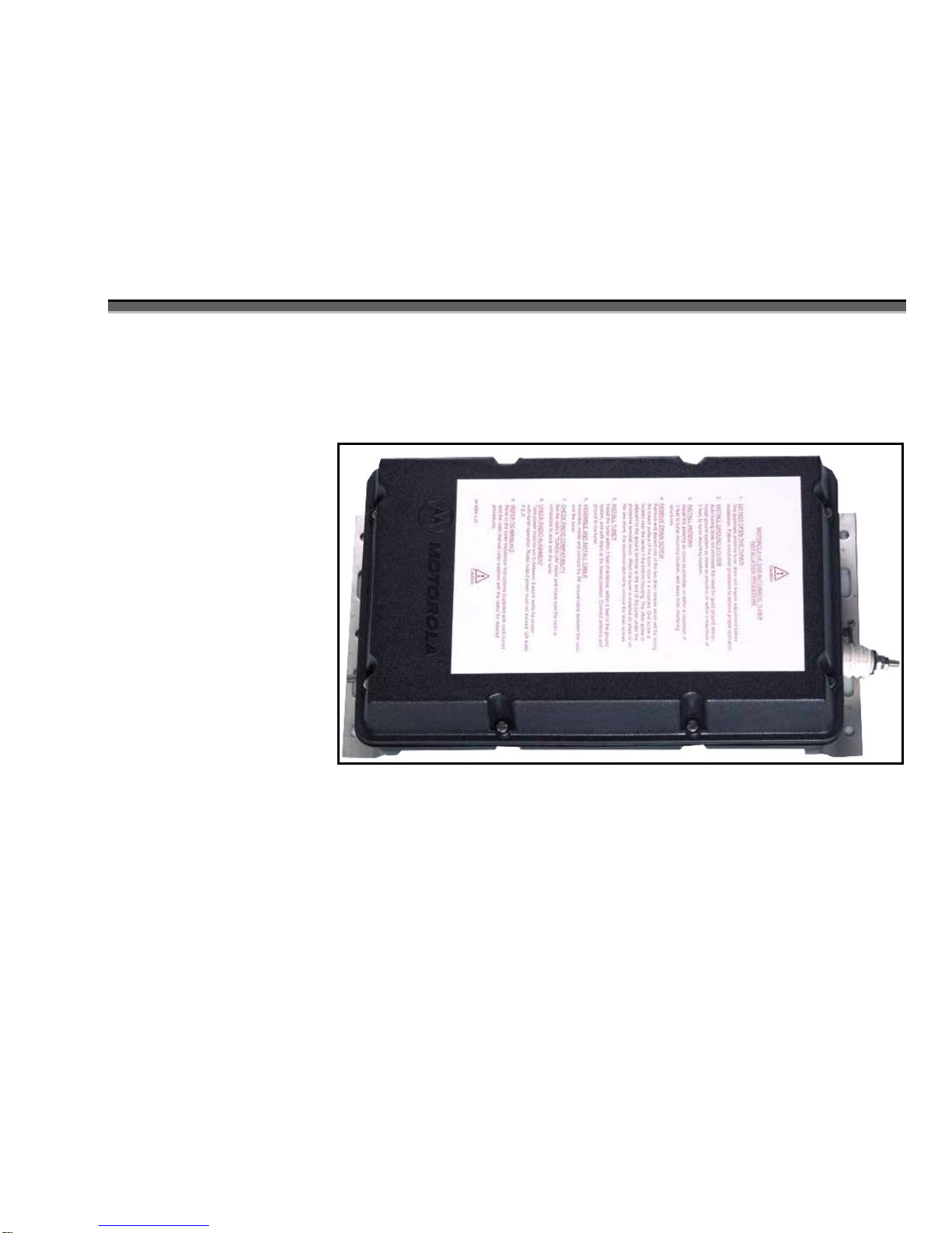
1.1 GENERAL DESCRIPTION
CHAPTER 1
DESCRIPTION
1.2 FUNCTIONAL DESCRIPTION
The HF-SSB Automatic Antenna Tuner Unit (ATU)
model F2265A is an antenna matching network that
provides efficient RF power transfer from the radio
system to the antenna.
The ATU handles up to 125 watts Peak Envelope
Power (PEP). It is used for voice and Continuous
Wave (CW) Morse code communications.
ATU F2265A matches the antenna impedance to the
50 Ω output impedance of the radio system, with a
nominal VSWR of 1.5 in the 1.6 to 30 MHz frequency
range.
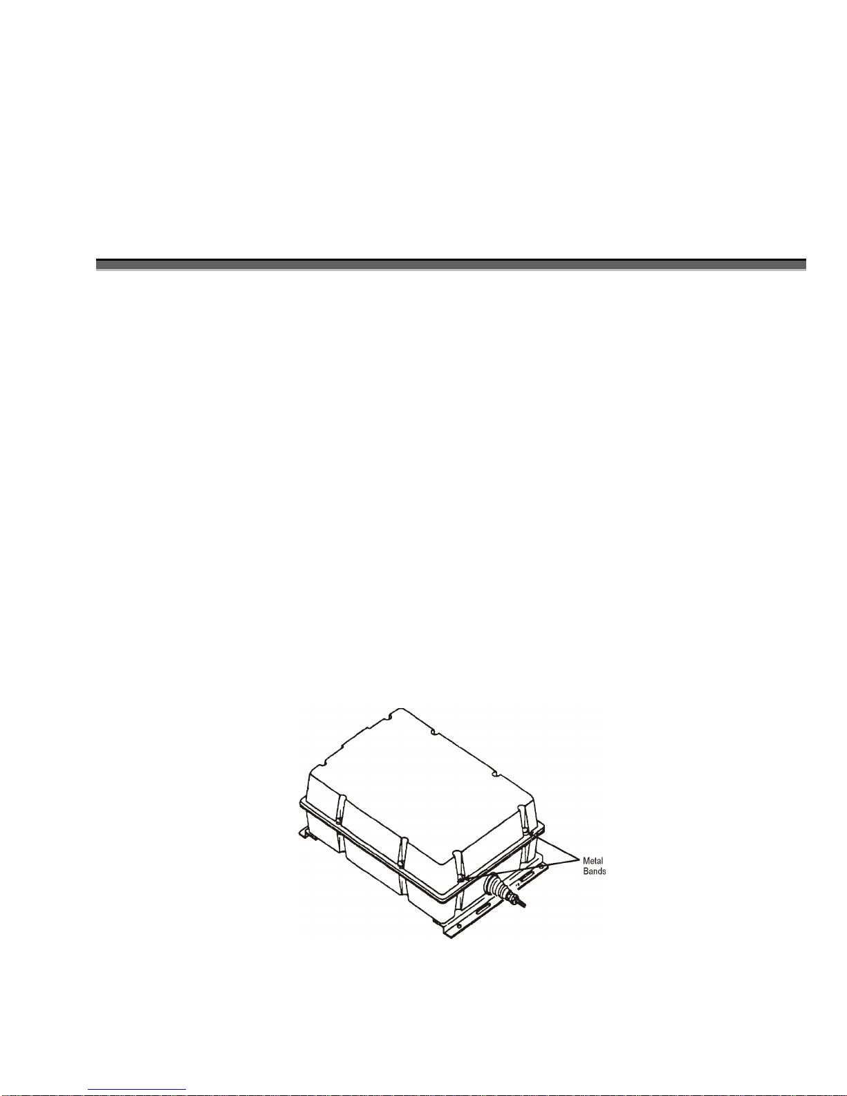
The ATU is housed in a weatherproof case, allowing
outdoor installation, such as open roofs.
The F2265A Automatic Antenna Tuner (ATU) operates
in the 1.6 to 30 MHz frequency range at 125 watts peak
envelope power (PEP). The ATU automatically selects
the network component for the antenna matching, thus
eliminating the need for programming, presetting,
manual tuning and adjustment during the installation
and the operations.
A microprocessor circuit checks the antenna matching
each time the channel is changed and then
automatically switches inductors and capacitors in and
out of the matching network. The tuning data for a
given channel is stored in a memory and kept as long as
the ATU is on. The next time the channel is used, the
stored tuning data for that channel is used, considerably
reducing the tuning time (provided that the VSWR is
within the specified limits).
Figure 1-1. ATU General View
1-1/(1-2 Blank)
1-1
Page 12

Page 13

CHAPTER 2
INSTALLATION
2.1 GENERAL
The radio and ATU are factory-preset for proper tuning
operation and require no additional adjustment or
programming.
2.2 RECOMMENDED EQUIPMENT
2.2.1 TOOLS
- Nut driver 7/16" (VACO S-14, USA)
- Nut driver 5/16" (VACO S-10, USA)
- Flat blade screwdriver 7/16"
2.2.2 ACCESSORIES
For mobile installations:
FKN4314 High voltage cable kit
(supplied with the ATU)
FKN4589 RF coax cable
(supplied with the ATU)
For base station installations:
FKN4314 High voltage cable kit
(supplied with the ATU)
FKN4612 30 ft cable kit
FKN4613 100 ft cable kit
2.3 MOBILE INSTALLATION
INSTRUCTIONS
2.3.1 CABLE KITS
2.3.2 INSTALLATION INSTRUCTIONS
NOTE
The installation instructions included in
the label on the unit cover apply to base
station installation. Disregard these
instructions in case of a mobile
installation.
2.3.2.1 Antenna and ATU Location
The antenna and ATU locations on a vehicle are the
most critical parts of a mobile installation, since they
have a great influence on the effective radiated power.
2.3.2.1.1 Antenna Location
The ATU tunes mobile whip antennas as specified in
the PERFORMANCE SPECIFICATIONS section.
However, 15 foot whip is recommended for best
efficiency.
For short range communications (ground waves), a
vertical (non-bent) antenna is preferred. For long range
communications (sky waves), a bent antenna is
preferred. The antenna may be bent and tied down to
the vehicle's body with a nylon cord.
The best antenna location is the vehicle's rooftop,
where the antenna is not obstructed by metal objects.
Roof center installation provides good symmetricalomnidirectional radiation patterns.
If roof top installation is impossible, a side wall
installation, with the antenna as far away from the side
wall and as high as possible, will suffice.
The ATU basic model is supplied with the FKN 4314
High Voltage Cable Kit and the FKN4589 RF coax
cable kit. A special RF Choke is incorporated in the RF
cable assembly to eliminate grounding problems.
If the antenna's height above ground is limited, it is
preferred to install the antenna as high as possible and
to bend and strap it down to the required height (as
opposed to installing the antenna close to the ground,
such as in a bumper mounted installation).
2-1
Page 14
Installation
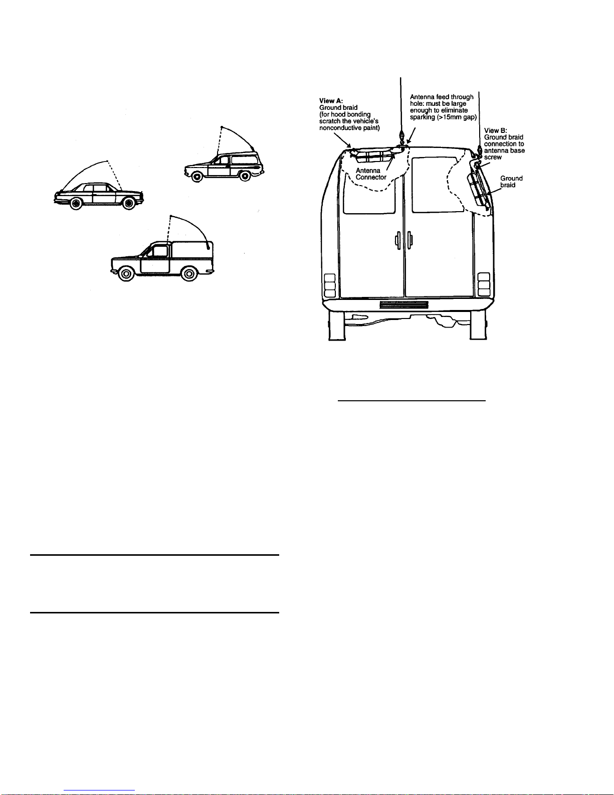
The suggested mobile installations are illustrated in
Figure 2-1.
Figure 2-1. Suggested Mobile Installations
2.3.2.1.2 ATU Location
The ATU should be mounted in a location, where the
ATU output (antenna) connector is as close as possible
to the antenna input connector.
The maximum allowed lead-in wire length is 30 cm.
Any reduction in the lead-in wire length improves the
system performance. A 10 cm wire ensures good
radiation results.
Examples of effective installations are given in Figure
2-2.
NOTE
If installation restrictions exist, the ATU
may be installed on the vehicle's exterior.
IMPORTANT
A properly installed ATU adds noise
immunity to the radio system.
Figure 2-2. Effective Installations
2.3.2.2 Antenna ATU Interconnections
2.3.2.2.1 Whips Longer than 16 ft and Wire
Antennas
Step 1. Connect the ATU output connector to the
antenna connector with the shortest wire possible. A 12
AWG insulated wire is sufficient for this purpose. The
lead-in wire should have about 3" of clearance from
metal walls, grounding braids, etc. You may use the
FKN4314A High Voltage Cable Kit supplied with the
ATU.
Step 2. Connect the ATU ground terminal to the
vehicle body with a wide grounding braid, as shown in
Figure 2-2, view A. Ensure that the grounding braid is
as short as possible. If the ATU is installed on the inner
side of the vehicle's body (see Figure 2-2, view B), a
second grounding braid should be placed beneath the
ATU and connected to one of the bolts securing the
antenna base.
2.3.2.2.2 16 ft or Shorter Whips
When connecting a 16 ft or shorter whip to the ATU,
you must use the high voltage cable kit FKN4314A
supplied with the ATU.
2-2
Page 15
Installation
NOTE
It is recommended to shorten the high
voltage cable as much as possible,
providing that the distance between the
antenna base and the ATU is short enough.
Use the appropriate ring lug, provided
separately in the kit, to reassemble the
shortened cable.
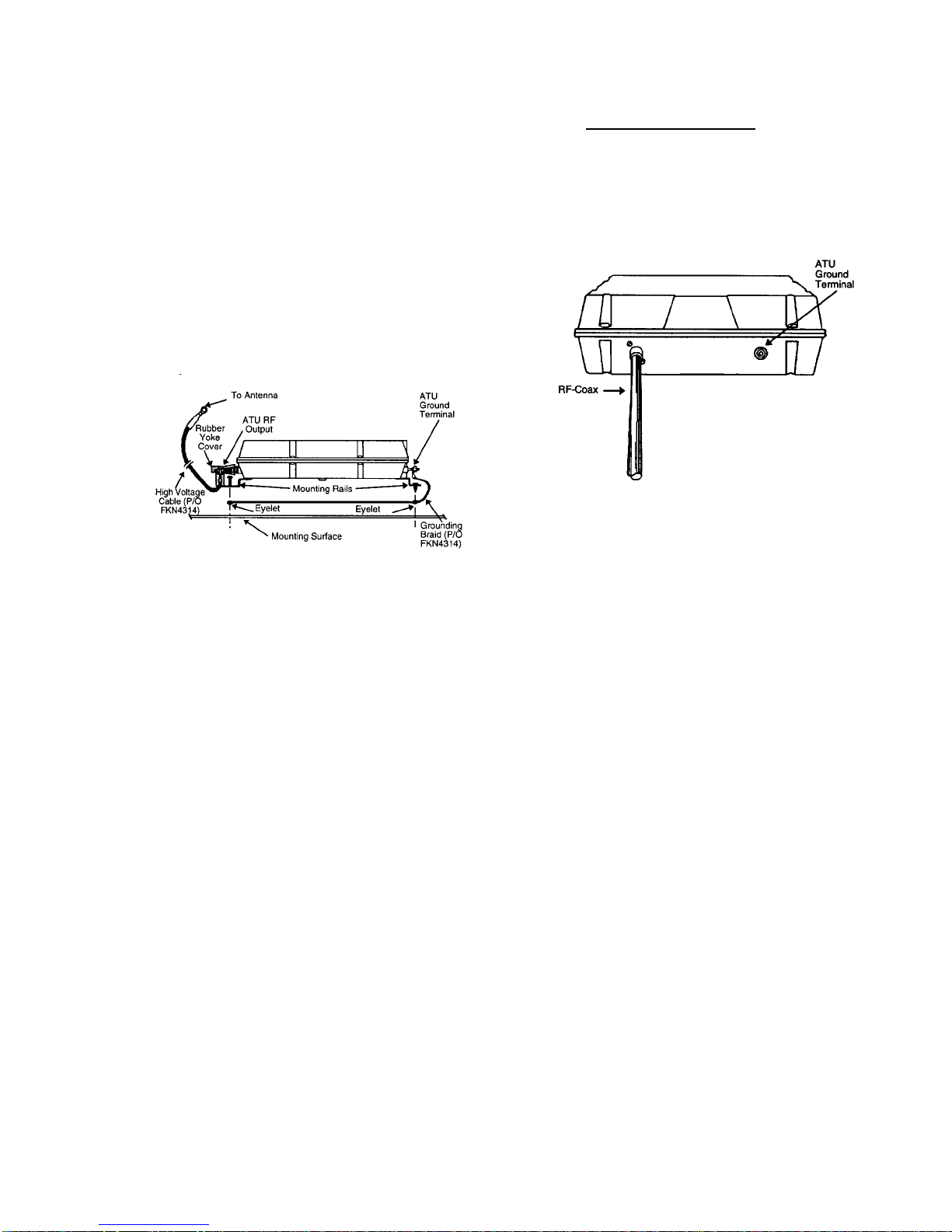
Step 1. Attach the high voltage cable conductor to the
ATU RF output (see Figure 2-3). While holding the
high voltage cable, push the rubber yoke cover until it
slips on the yoke.
Figure 2-3. FKN4314A High Voltage Cable
Attachment
2.3.2.3 Cable Interconnections
Step 1. Route the RF cable between the ATU and the
radio.
Step 2. Connect the RF coaxial cable to the ATU's RF
input.
Step 3. Connect the RF cable to the radio.
Figure 2-4. ATU Electrical and Mechanical
Connections
Step 4. Perform the operational check given in
paragraph 2.3.3.
Step 2. Attach the grounding braid of the high voltage
cable kit to the ATU ground terminal (see Figure 2-3).
Step 3. Route the grounding braid between the ATU
mounting rails and the mounting surface. Align the
grounding braid eyelets with the holes in the mounting
rails and mount the ATU using the tapping screws
provided (see Figure 2-3).
Step 4. If the grounding braid does not provide a good
ground to the vehicle's body, connect the supplied
grounding wire between the ATU ground terminal and
a good grounding point near the antenna base using the
supplied tapping screw and split washer.
Step 5. Attach the other end of the high voltage cable
to the antenna base.
2.3.3 OPERATIONAL CHECK
When the system installation is completed, perform the
following operational check:
Step 1. Install an in-line wattmeter between the radio
and the ATU.
Step 2. Turn on the radio.
Step 3. Key the radio and whistle into the microphone;
observe the forward and reverse power reading on the
wattmeter. The forward power should be at least three
times greater than the reverse power.
Step 4. Perform step 3 for each channel used.
2-3
Page 16
Installation
2.4 BASE STATION INSTALLATION
INSTRUCTIONS
2.4.1 ANTENNA INSTALLATION
The recommended length of antennas for base stations
is 23 to 60 feet for long wire antennas and 23 to 35 ft
for whips, in the specified frequency range. Shorter
antennas are recommended for mobile installations
only.
2.4.1.1 23 to 35 Feet Whip Antennas
23 to 35 feet whip antennas are suitable for medium to
long-range communications. The antenna should be
located away from interfering structures, such as metal
masts, building and metal wires parallel to the antenna.
The distance from these interfering structures should be
about one wavelength (see footnote below) of the
lowest frequency used.
2.4.1.2 23 to 60 Feet Wire Antennas
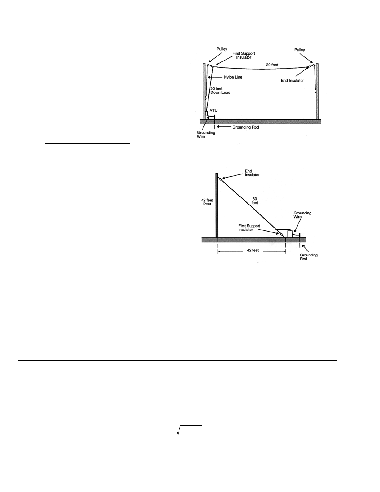
The wire antenna can be installed in one of the
following configurations: inverted "L," and sloping
wire, as illustrated in Figure 2-5 and Figure 2-6.
The antennas illustrated in these figures are suitable for
systems using frequencies below 5 MHz. Optimum
antenna performance is achieved when the antenna is
approximately a quarter of a wavelength long (see
footnote below).
Figure 2-5. Inverted "L" Antenna
Figure 2-6. Sloping Wire Antenna
If the lowest used frequency is higher than 5 MHz, a
good practice is to shorten the overall antenna length to
approximately a quarter of a wavelength with the
configuration and the wire length ratio as in Figure 2-5
and Figure 2-6.
For antenna length computational purposes only, the following formulas may be used for calculating the
wavelength:
Wavelength (m) =
If the system uses frequencies ranging between f1 and f2, a satisfactory antenna length is a quarter of a wavelength
of the mean frequency, where:
2-4
285
Wavelength (ft) =
)(MHzf
mean = 21 ff ×
f
935
)(MHzf
Page 17
Installation
2.4.2 ANTENNA GROUND PLANE
2.4.2.1 General
The ground plane provides an RF current return path
for the antenna. For efficient operation, the loss
resistance in the ground must be small in comparison to
the antenna radiation resistance. Furthermore, the
effective length of the ground system largely affects the
shape of the antenna radiation pattern. A poor ground
will cause an otherwise good radio to perform poorly.
This section provides a description of a ground plane
and explains its installation.
2.4.2.2 Location
A good ground plane must be spread out with the
antenna located normally in the center.
2.4.2.2.1 Ground Plane for Whip Antennas
(23 to 35 feet, 7 to 11 meters, non-roof
mounted)
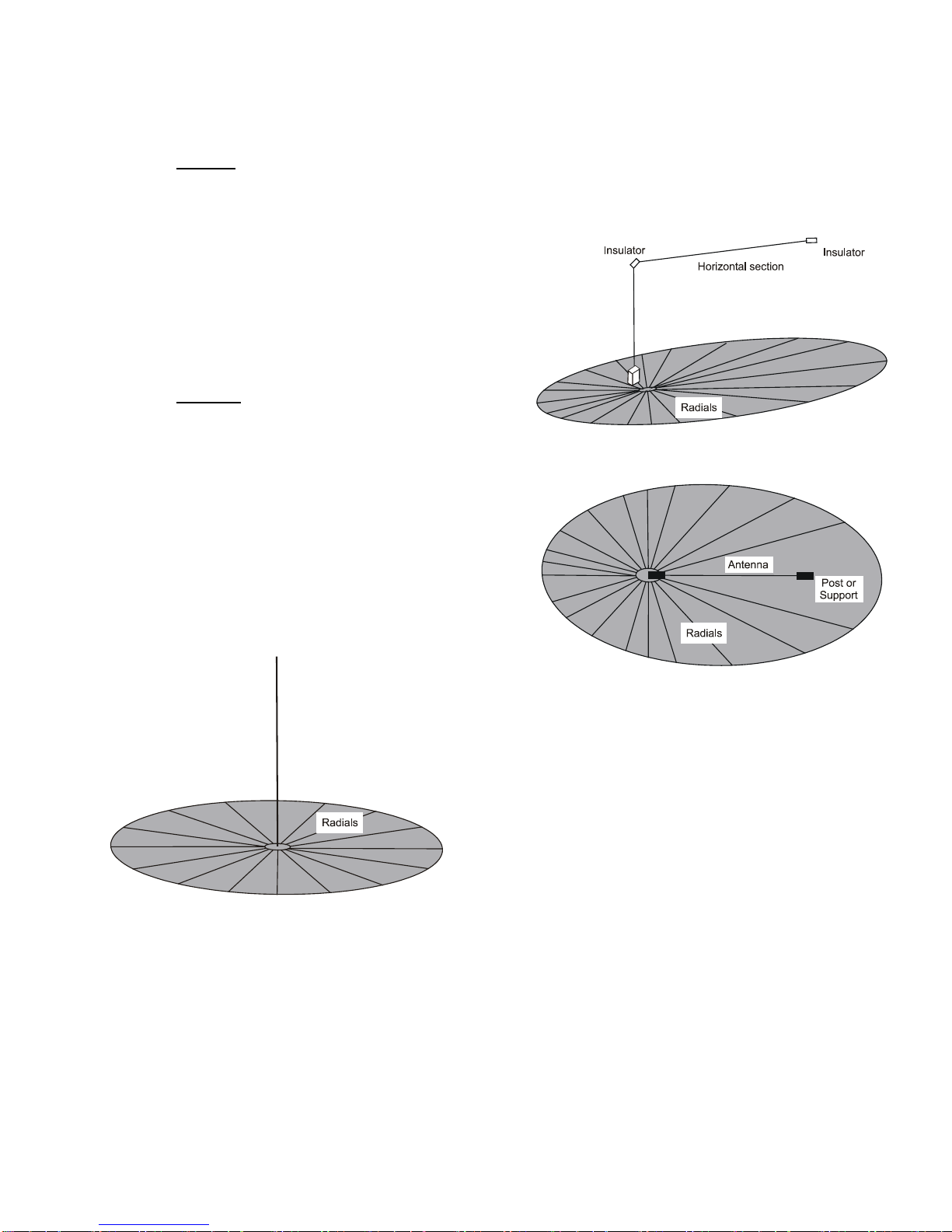
12 radials, 35 to 60 feet long, form an adequate ground
plane (see Figure
the longer communication ranges. A ground rod should
be driven into a ground near the base of the antenna to
provide a lightning discharge pass.
2-7). The 60 feet radials are used for
The ground plane shape for an Inverted "L" wire
antenna should be distorted with most of the surface
area placed under the antenna (see Figure
2-8). The
sloping wire antenna should have a circular ground
plane shape with the antenna feed point at the center.
a. Side View
b. Top View
Figure 2-7. Practical Ground Plane for a Whip Antenna
2.4.2.2.2 Ground Plane for Wire Antennas
(non-roof mounted)
Twelve radials, 35 to 60 feet long, will form a good
ground plane. A ground rod should be driven into the
ground close to the antenna base to provide a lightning
discharge pass.
Figure 2-8. Ground Plan for Inverted "L" Wire
Antenna
2.4.2.2.3 Ground Plane for Roof Mounted Whips
and Wire Antennas
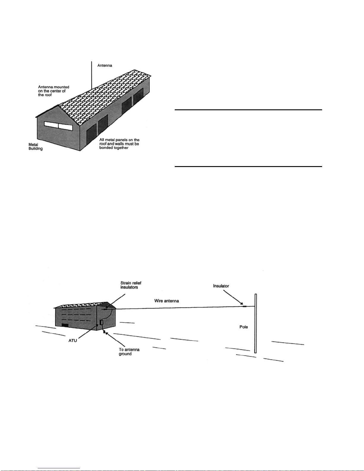
A fairly effective ground can also be achieved by
grounding to the building structures or metal roof (see
Figure
2-9), provided that the roof pieces are
electrically bound together. Antennas far from earth on
insulated structures require a ground plane (or radial
system).
Two or four radials cut to a quarter or half wavelength
for each frequency used (3/8 x wavelength is a fair
optimum) form an effective ground plane above 7
MHz. Below 7 MHz, the required length gets
unreasonably long; however, more than four radials 30
to 70 feet (9.1 to 21.3 m) long are recommended. A
direct connection to a ground rod driven into the earth,
2-5
Page 18
Installation
or a connection to a water pipe of the building, is
required for lightning protection.
Figure 2-9. Practical Ground Using a Metal Building
2.4.3 ATU INSTALLATION
INSTRUCTIONS
Step 1. Locate the ATU as close as possible to the
antenna and close enough to the ground system so that
the ground lead is less than 5 ft (1.5 m).
Step 2. Attach the ground braid of the high voltage
cable kit to the ATU ground terminal (see Figure
2-3).
Step 3. If a wire antenna is used, connect it directly to
the ATU RF output terminal. Use mechanical strain
relief similar to the one shown in Figure
2-10.
Step 4. Connect the shortest possible ground lead
between the antenna ground plane and ATU ground
terminal. The base station ground, ATU ground and the
antenna ground plane must be bond to the earth ground.
CAUTION
Do not install the ATU without the
earth ground. The earth ground is
required both for the ATU efficient
operation and for lightning
protection.
Step 5.
Route the RF coaxial cable between the ATU
and the radio.
Step 6. Connect the RF coaxial cable to the ATU's RF
input.
Step 7. Connect the RF cable to the radio.
Step 8. Perform the operational check given in
paragraph 2.3.3.
Figure 2-10. Typical Base Station Installation Using a Wire Antenna
2-6
Page 19

CHAPTER 3
THEORY OF OPERATION
3.1 FUNCTIONAL DESCRIPTION
3.1.1 ATU FUNCTION
The ATU allows for an effective energy transfer
between the radio and the antenna. This is basically
achieved by meeting the following requirements:
• Minimizing the insertion loss of the matching
network.
• Preventing mismatch losses by presenting
appropriate impedances to the radio power
amplifier and the antenna.
3.1.2 ATU OPERATION
The DC power is supplied to the ATU via the RF cable.
After changing the frequency, the radio interrupts the
DC power supply via the RF cable for about 50
milliseconds. After the power returns, the ATU
performs the power-on tuning process. During the
power interruption, a special backup power is supplied
to the tuning data storage, to prevent data loss.
The Tuning Process: When the DC power returns (50
msec after changing the frequency), the Tuner Control
circuit (which initiates and controls the ATU operation)
turns on. The tuner control circuit sends a signal to the
radio to generate an output signal at a tune level
(3-6 W) and starts the tuning process.
First, the ATU verifies that the tune power at its input
(V-FORWARD) is within the predefined range
(3-6 W). Power above this range can damage the relays
during the Hot Switching, while power below the
predefined range can cause inaccurate tuning.
If the tune power is within the specified range, the ATU
captures a 20ms sample of the signal. The sample
signal frequency is divided by 128 and measured by a
counter. Based on the above data, the frequency
measurement resolution is as follows:
Resolution =
The ATU reads the tuning data corresponding to the
measured frequency from its internal memory (such
data exists if tuning was previously performed for this
frequency). The ATU sets the tuning network according
to that data and measures the resulting VSWR. If
VSWR<2 the tuning is completed. If it is higher, a new
tuning cycle is started.
The tuning process principle is based on crossing the
G=1 circle in the positive part of the Smith Chart using
a series inductance, and then moving towards
VSWR=1.5 using a parallel capacitance at the input.
When the ATU completes the tuning process, it stores
the tuning network data in memory in a location
corresponding to the current frequency.
After the tuning process is completed, the ATU shorts
its sensor terminals to ground to protect them from high
power, and its microprocessor enters an idle state to
prevent noise from the receive channel. The relays’
state is maintained by using latches on the relay control
lines.
Radio Switching out of TUNE Mode: A sensor in the
radio measures the reflected power at the radio output
every 100ms. If this power is stable and low enough
over a period of 300ms, the radio will switch out of
TUNE mode assuming that the tuner has completed the
tuning. If the tuning has not been completed after 3
seconds, the radio will automatically switch out of
TUNE mode.
1
ms20
=×
Hz6400128
3-1
Page 20

Theory of Operation
3.2 BLOCK DIAGRAM DESCRIPTION
The ATU block diagram is shown in Figure 3-1 and
described in the following sections.
signal indicates the forward power.
• V
f
• V
signal indicates the reverse power.
r
• An RF sample for calculating the signal frequency.
3.2.1 RF MATCHING NETWORK
The RF signal from the radio is applied to the RF
Matching Network via the RF Sensor. The RF
matching network is a combination of inductors and
capacitors. The ATU changes the network parameters
by switching the inductors and capacitors in and out of
the network.
The quality of the network and its components
determines the effectiveness of the energy transfer
between the radio and the antenna. Therefore, the
network components have high-Q (quality factor) and
the tuning algorithm is very sophisticated.
3.2.2 RF SENSOR
The RF sensor samples the RF signal, converts the
samples to analog levels (between 0-5 V) and transfers
the data to the Tuner Logic. The following data is
provided on the RF signal:
• PH-L and PH-C signals indicate whether the load is
inductive or capacitive.
signal indicates on which G circle on the Smith
• V
g
Chart the load is located (G=
1
).
R
3.2.3 TUNER LOGIC
The Tuner Logic circuit performs the following
functions:
• Detects channel change in the radio (based on DC
interrupting on the RF cable while the channel is
changed).
• Calculates the frequency of the RF signal sample
provided by the RF sensor.
• Controls the tuning process: it implements the
tuning algorithm and sends commands to the relay
drivers that control the matching network
components.
• Stores the tuning state for each frequency.
• Shorts the RF sensor outputs to the ground after
completing the tuning process. This grounding is
required for protecting the Tuner Logic circuits and
the sensor components from high power during the
normal radio transmission.
When the tuning is completed, the Tuner Logic circuit
deactivates the relay control commands and enters an
idle state.
3-2
Page 21
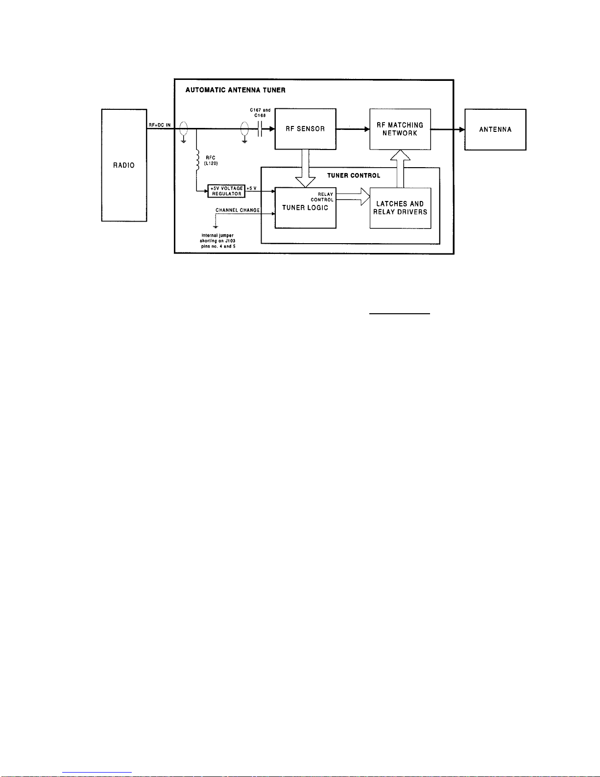
Figure 3-1. ATU Block Diagram
Theory of Operation
3.2.4 LATCHES AND RELAY DRIVERS
The Latches and Relay Drivers control the components
of the matching network. The relay drivers activate the
RF relays that switch inductors and capacitors in and
out of the network. The latches keep the relays
activated after the tuning has been completed and the
relay commands have been removed.
3.3 DETAILED CIRCUIT
DESCRIPTIONS
Throughout the detailed circuit description you are
referred to the Antenna Tuner Board.
3.3.1 RF SENSOR CIRCUIT
The RF input is applied to transformer T101 via
connector J101. T101 includes two current
transformers, each of which generates a sample of the
RF input, as follows:
• One sample is used for sensing the phase of the
input signal.
• The other sample is used for sensing the V
V
(the G circle in the Smith Chart, forward power
r
and reverse power, respectively).
, Vf and
g
3.3.1.1 Phase Sensor
The phase sensor measures the phase difference
between the input signal voltage and the input signal
current. A capacitor network made up of C204, C203
and C184 samples the voltage. The voltage sample is
applied to pin 6 of the T101 phase sensing transformer
and is thus added to the current sample generated in the
transformer. Pin 7 of T101 provides a vector sum of the
input signal voltage and current, while pin 5 provides
the vector difference.
Both outputs are applied to peak detectors (one is made
up of CR101, R108, R112 and C132, and the other is
made up of CR102, R109, R113 and C133). The peak
detectors generate DC voltages PH-C and PH-L, which
are proportional to the amplitudes of the above
mentioned vector sum and vector difference. The input
signal phase characteristics is determined as follows:
- If PH-C > PH-L, the input signal has capacitive
characteristics.
- If PH-C < PH-L, the input signal has inductive
characteristics.
3-3
Page 22

Theory of Operation
3.3.1.2 V
and V
f
Sensor
r
3.3.1.2.1 General
Voltage representing the forward power (V
) is derived
f
by vector addition of appropriately scaled samples of
the Total RF Current (I
Voltage representing the reverse power (V
) and Total RF Voltage (Vt).
t
) is derived
r
by vector subtraction of appropriately scaled samples of
and Vt.
I
t
3.3.1.2.2 Detailed Description
The current sample I
is taken from pins 8 and 9 of
t
T101 and converted to voltage using resistor network
R187 through R190. The voltages over resistors
R187 + R188 and R189 + R190 have inverted phases.
Two capacitor networks (C192, C193, C205, C206 and
C194, C195, C209, C210) provide the V
samples.
t
Diodes CR104 and CR105 perform a vector subtraction
and addition (respectively) of the V
The V
and Vr voltages are integrated over resistor and
f
and It samples.
t
capacitor networks (R104, R111, C123 and R103,
R110, C122, respectively) to provide DC voltages
representing the absolute values of the V
and Vr
f
vectors.
The V
and Vr signals are passed to the Tuner Logic
f
circuit for the VSWR calculation (see paragraph
3.3.3.2).
3.3.1.4 Frequency Sample
Capacitors C200, C211 and C212 sample the RF signal
during the tuning process. Sampling is enabled for a
duration of 20 milliseconds under control for the Tuner
Logic circuit. The sample signal FREQ is passed to the
Tuner Logic circuit.
During sampling, 12 Vdc is supplied to the cathode of
pin diode CR108 via R106 and L115 and keeps the
diode in the cut off state (the diode does not conduct).
When the sampling is completed the FREQ_SW signal
from the Tuner Logic circuit is applied to transistor
Q101. The transistor switches on and provides a DC
current path from CR108 diode's cathode to ground via
R191. Since the diodes' anode receives DC from the
Tuner Logic circuit via the FREQ line, the diode now
conducts and the RF signal on the FREQ line is shorted
to ground via CR108 and capacitor C134.
3.3.1.5 Vcc Voltage Supply
Voltage regulator U101 provides the +5 V Vcc to the
Tuner Logic circuit.
The DC power (typically 13.8 V) is received from the
radio via the RF input coaxial cable. This power is
interconnected to the 12 V internal power line via RF
choke L120.
3.3.1.6 Spark Gap
A 300 V spark gap (E101) protects the radio from high
voltage RF or spikes originating in the ATU.
3.3.1.3 V
As already mentioned, the V
on which the RF signal is located on the Smith Chart.
is derived by vector subtraction of appropriately
V
g
scaled samples of I
Pins 8 and 9 of T101 provide the current sample (I
which is converted to voltage using resistor network
R187 and R188. A capacitor network (C199, C207,
C208) provides the V
a vector subtraction of the I
R107 and capacitor C124 perform integration on the V
vector to provide a DC voltage proportional to the
vector absolute value.
Sensor
g
signal indicates G circle
g
and Vt signals.
t
sample. Diode CR106 performs
t
from Vt. Resistor R102,
t
3.3.2 RF MATCHING NETWORK CIRCUIT
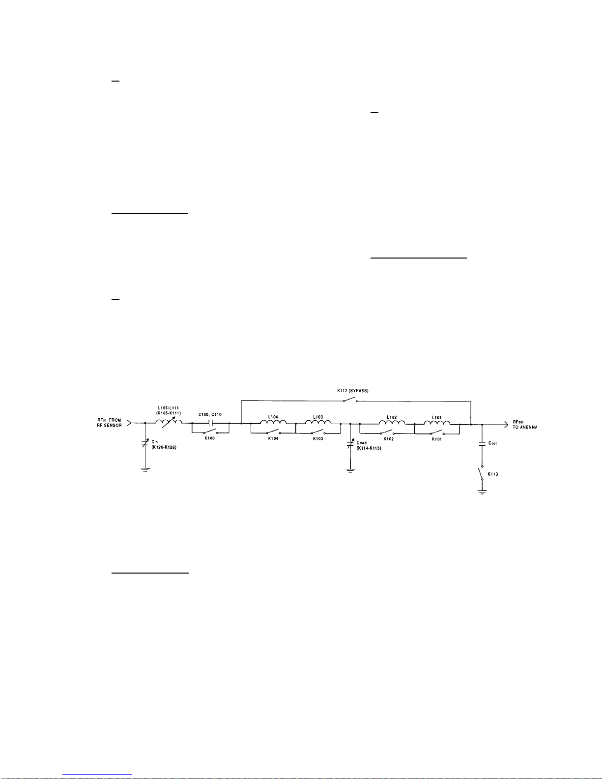
Refer to Figure 3-2 for the RF Matching Network
Block Diagram.
3.3.2.1 Series Inductor
The network includes a variable series inductor which
)
t
enables clockwise movement along constant R circles
on the Smith Chart, until the G=1 circle is crossed
towards the inductance side.
The variable inductor is made up of 11 high-Q series
inductors, that can be switched in and out of the
g
network using relays connected to each inductor in
parallel (K101 - K111). In general, the inductors' values
increase in a binary order (except for the L101 and 102
The integrated V
circuit for the G circle indication (see paragraph
signal is passed to the Tuner Logic
g
that have identical values, so as to cover the range
between 0.08 µH and 75µH).
3.3.3.2).
3-4
Page 23
Theory of Operation
3.3.2.2 C
The input capacitor network (C
in
) enables movement
in
towards the Smith Chart center after crossing the G=1
circle.
C
is made up of 26 capacitors (C169-C181, C183,
in
C185-C191, C196-C198, C201, C202) that can be
switched in and out of the network using relays K120K126. C
can accept one of 128 values ranging
in
between 0 pF and 9260 pF.
3.3.2.3 Series Capacitor
The series capacitor (C100, C110) is used either for
handling inductive loads or for overcoming high
frequency parasitic inductances on the line. The series
capacitor can be switched in and out of the network by
relay K100.
3.3.2.4 C
The output capacitor C
out
(C101-C106) enables
out
matching loads whose impedance real component is
above 50 Ω. C
can be switched in and out of the
out
network by relay K113. C
is most useful in the low
out
frequency range.
3.3.2.5 C
med
The function of the variable intermediate capacitor
(C111 through C117) is identical to that of C
C
med
However, C
is not connected directly in parallel to
med
the antenna and therefore it is more efficient and used
instead of C
C
value ranges between 0 pF and 275 pF in 4 steps
med
whenever possible.
out
under control of two relays (K114, K115). In addition,
allows tuning inductive loads when the series
C
med
capacitor (C100, C110) is not sufficient.
3.3.2.6 Bypass Relay (K112)
The bypass relay (K112) is used to bypass output relays
K101 through K104 when all of these four relays are
closed (inductors L101 through L104 are shorted). This
technique improves transfer efficiency, especially at
high frequencies.
out
.
Figure 3-2. RF Matching Network - Block Diagram
3.3.2.7 Relay Activation
A DC power is constantly applied to the relays unless
there are 50ms of DC interrupting during channel
change. The relays are activated by ground potentials,
applied by the Latches and Relay Drivers circuit to the
relay control terminals.
3.3.3 TUNER LOGIC CIRCUIT
Refer to Figure 3-1 for the ATU Block Diagram.
The Tuner Logic circuit controls the operation of the
Automatic Antenna Tuner. It is based on the 68HC11
microprocessor and performs the following functions:
• Detects channel change and waits for RF tune level
from the radio (based on DC interrupting during
channel changes).
• Counts the frequency of the RF sample.
• Processes the sensor data and performs the tuning
algorithm based on this data.
• Controls the activation of the relay drivers.
3-5
Page 24

Theory of Operation
• Shorts the sensor outputs to the ground after the
tuning process is completed.
• Stores the tuning data for each frequency used.
• Keeps the tuning data storage alive after the ATU is
turned off for a minimum of 0.5 second (this
function is necessary for the 50ms of DC
interrupting when the channel is changed).
• Enters idle state after the tuning process is
completed and the tuning data is stored. This
feature minimizes the noise on the receive path
during reception.
3.3.3.1 Frequency Counter
The frequency sample FREQ from the RF Sensor is
converted to square wave by U3 and divided by 128 by
U15 and U16. The divided signal is applied to the
microprocessor input PA7. The microprocessor counts
the signal frequency in a 20 millisecond time slot.
Therefore the frequency measurement accuracy is 6400
Hz calculated as follows:
1
−
3
⋅
sec
1020
=×
Hz6400128
3.3.3.2 Sensor Data Processing
The sensor data is applied to microprocessor inputs PE0
through PE7. An internal A/D converter converts the
data into a digital format, in which all the calculations
are performed. The following calculations and
decisions are done:
• Calculating the VSWR:
V
R
1
+
V
VSWR
=
F
V
R
1
−
V
F
• Calculating the location on the Smith Chart in
relation to the G=1 circle:
- if V
g>Vf,
then G<1;
• Determining the load characteristics:
- if PH-C>PH-L, the load is capacitive;
- if PH-L>PH-C, the load is inductive.
3.3.3.3 Shorting the Sensor Outputs
After the tuning process is completed, the Tuner Logic
circuit shorts the signal lines from the sensors to a
ground, to protect the logic circuits and the sensor
components from high power during normal
transmission.
A 100 Ω resistor and a FET switch are connected
between the sensor outputs and the ground (R45-R49
and Q27-Q31). A control signal from the
microprocessor output PA6 turns on the FET switches.
The signal F_SWITCH generated by the
microprocessor at pin PA5 controls the shorting of the
frequency sampling circuit in the RF Sensor. Refer to
paragraph 3.3.1.4 for a detailed description of the
frequency sampling circuit.
3.3.3.4 Tune Data Memory
The Tuner Logic circuit saves the tuning data for each
tuned frequency in RAM U9. This data is stored as long
as the ATU is on.
3.3.3.5 Relay Driver Activation
The microprocessor controls the relay activation via the
SPI BUS serial bus. The serial control data is passed to
the Latch and Relay Drivers circuit.
3.3.4 LATCHES AND RELAY DRIVERS
CIRCUIT
The relay control data received from the Tuner Control
circuit via the SPI BUS, is applied to shift registers
U10-U13. The shift registers convert the serial data into
parallel. Each shift register provides 8 bits, all of which
are combined into a 32 bit parallel bus
(DRIVERS_BUS).
The DRIVERS_BUS bits are applied to 26 transistors
that actually drive the relays via the RELAY_BUS.
- if V
, then G>1.
g<Vf
• Verifying that the tune power at the ATU input is
within the predefined range (3-6 W):
- if V
<V
f
or Vf>V
low
, the tuning request is
high
rejected and the ATU is bypassed.
3-6
 Loading...